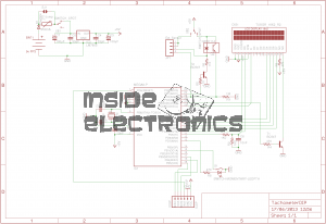
Here is an AVR powered optical tachometer design, that I adapted from the schematic found here.
I made a couple of changes to the circuit & designed a PCB & power supply module to be built in. The original design specified a surface mount IR LED/Photodiode pair, however my adjustment includes a larger IR reflectance sensor built onto the edge of the board, along with a Molex connector & a switch to select an externally mounted sensor instead of the onboard one.
There is also an onboard LM7805 based power supply, designed with a PCB mount PP3 battery box.
The power supply can also be protected by a 350mA polyfuse if desired. If this part isn’t fitted, then a pair of solder bridge pads are provided within the footprint for the fuse to short out the pads.
For more information on the basic design, please see the original post with the link at the top of the page.

Here is an archive of the firmware & the Eagle CAD files for the PCB & schematic design.

Hello,
My name is Drew Pintus, and I’ve been spending some time looking at your site, experimental-engineering.co.uk. I noticed you have a great electronics building site, so I thought I would alert you of my site, http://www.datasheets360.com.
The site has 70 million electronic components, each with its PDF datasheet. We’re working on scaling the site up to 350 million parts (We should be up to about 180 million this summer).
My site has inventory and pricing from many of the top distributors. It also features a part number search that I believe is very efficient.
Please take a look at my site and share it with your users if you’d like. I believe your users would benefit even more from the great site you already have. Don’t hesitate to contact me via email if you have any questions.
Thank you!
Drew Pintus