
Here is a teardown of the Datakom DKG-171 generator transfer controller. Here is the front of the unit, with the pictogram of the system, the indicator LEDs & the generator test button.
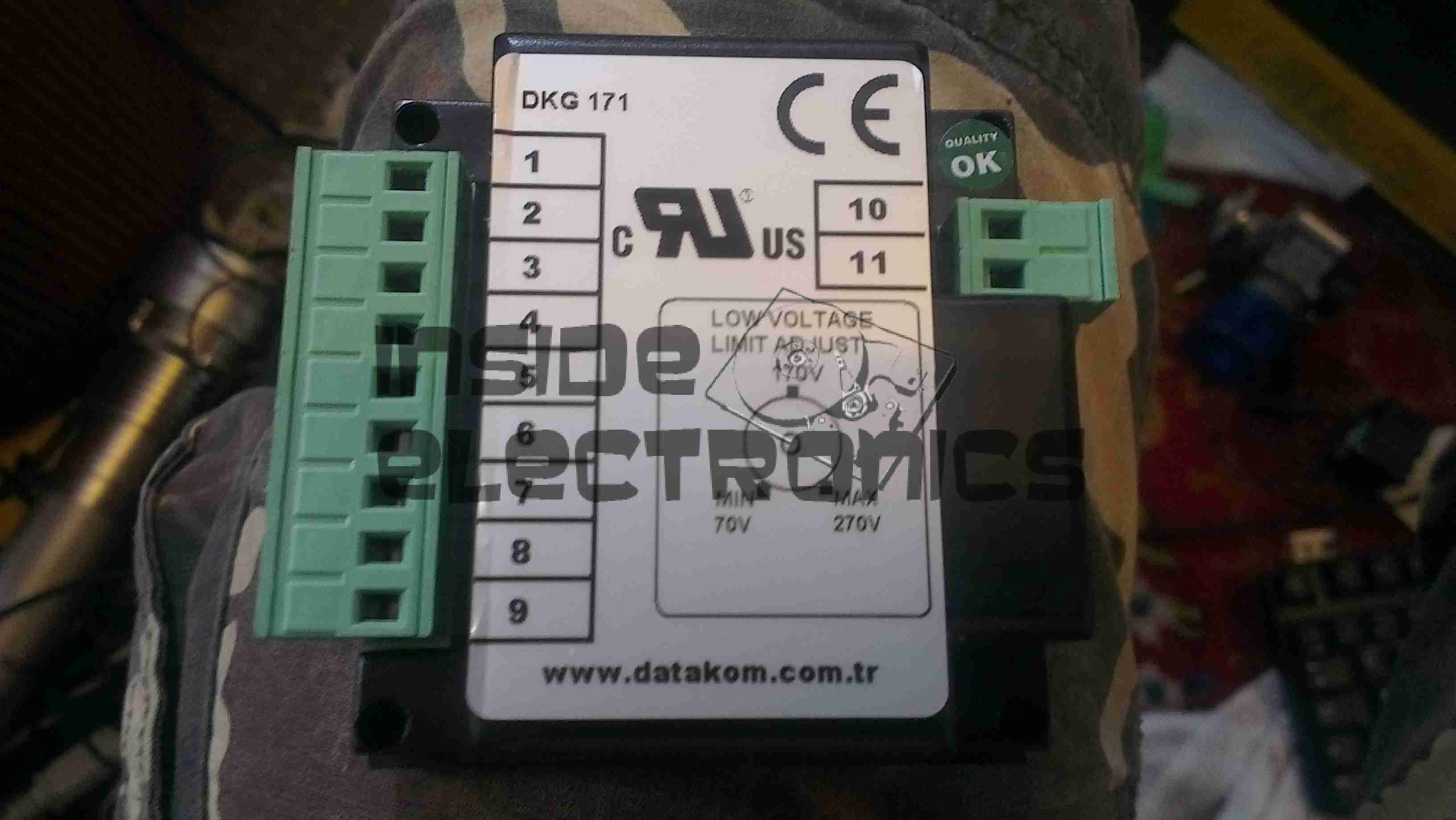
The rear of the unit features the connection points for the mains, generator & generator control I/O.
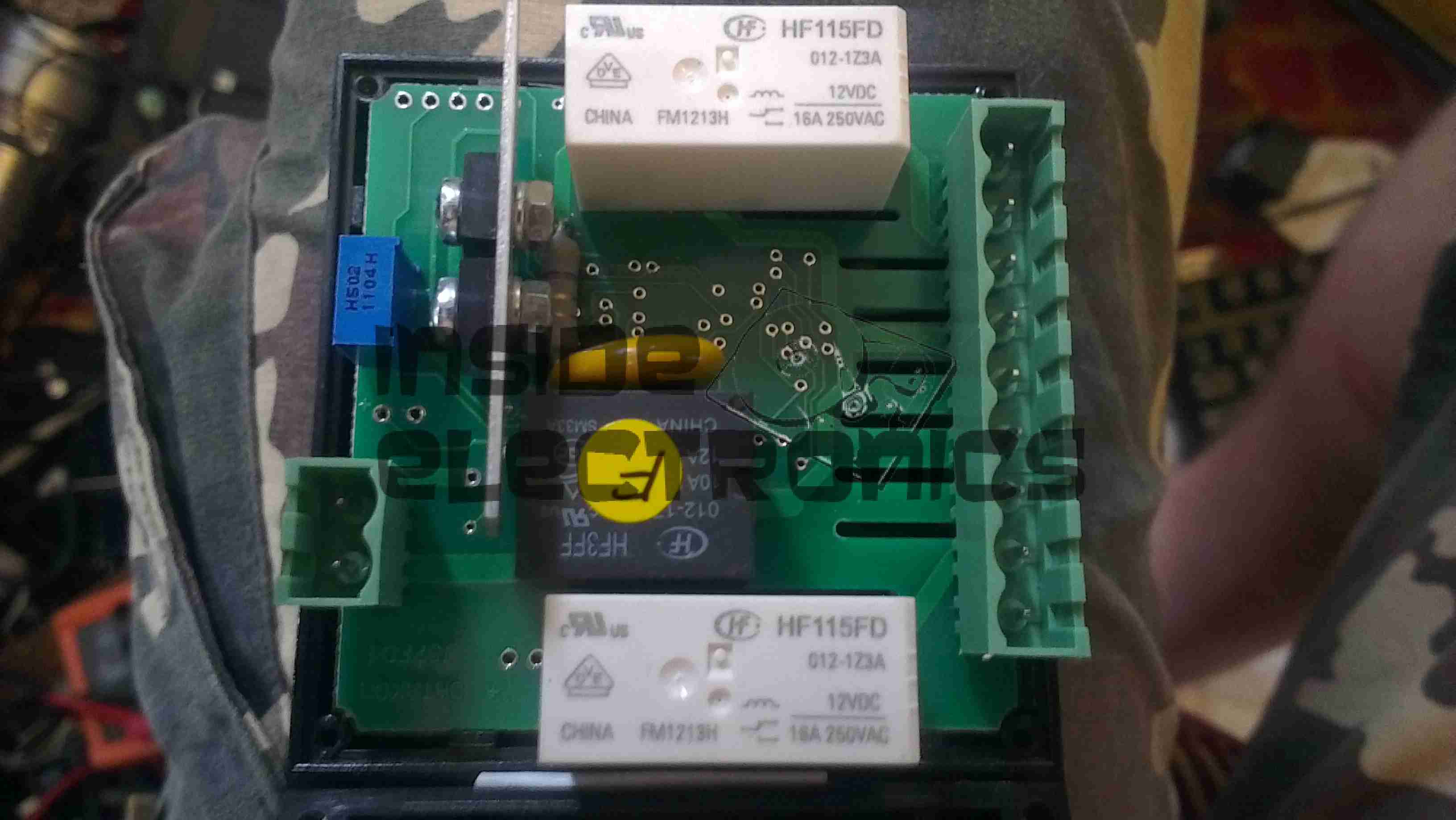
Rear of the PCB with the control relays. The two larger relays switch in the remote contactors to switch the mains supply over between the grid & the generator, while the smaller relay switches 12v power out to a terminal to automatically start the generator.
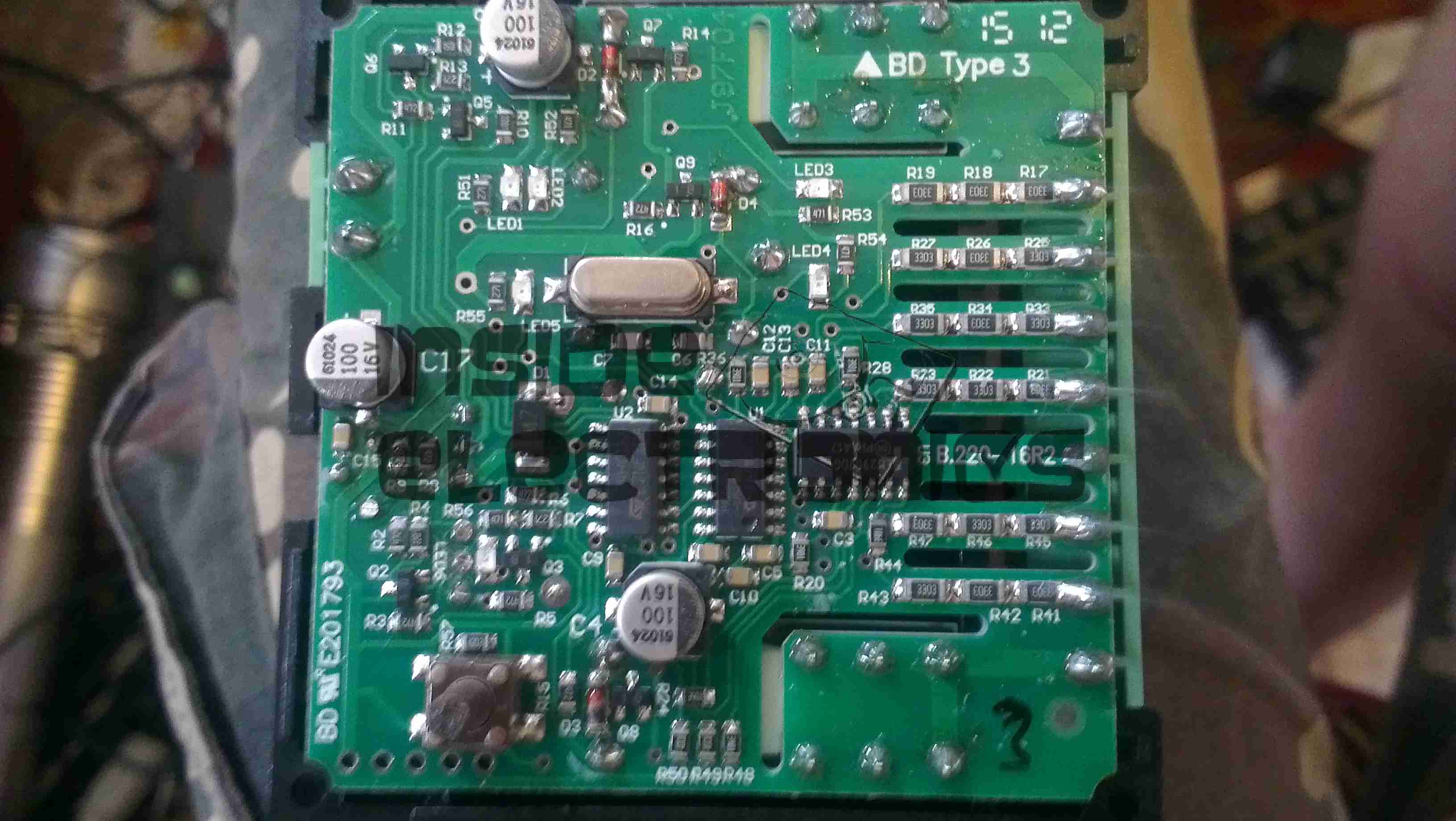
Front of the PCB with the control logic & main PIC microcontroller.
