Now the final bits have arrived for the SWR Meter module, I can do the final assembly.
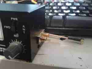
Here the SMA connectors are installed on the side of the eBay meter, for forward & reverse power tap.
These are simply tee’d off the wiring inside the meter where it connects to the switch.
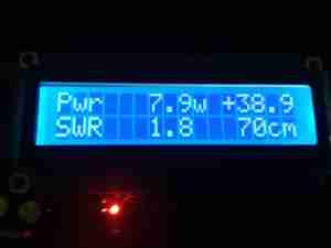
The meter is connected to the module via a pair of RG58 SMA leads, above is a readout before calibration, using one of my Baofeng UV-5Rs.
I’m using my GY561 eBay Power Meter as a calibration source, and as this isn’t perfect, the readings will be slightly off. If I can get my hands on an accurate power meter & dummy load I can always recalibrate.
Tools are only as accurate as the standard they were calibrated from!
After calibration, here’s the readings on 2m & 70cm. These readings coincide nicely with the readings the GY561 produce, to within a couple tenths of a watt. SWR is more than 1:1 as the dummy load in the GY561 isn’t exactly 50Ω.
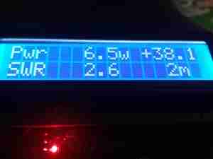
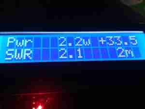
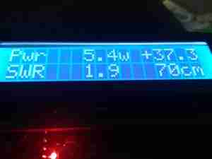

Shortly I’ll calibrate against 6m & 10m so I can use it on every band I have access to 🙂

I have build this couple weeks ago, until now i havent calibrate my devuce, because i dont know how it is.. when it not connected to coupler, it reading very wierd, watt and swr value was not take to zero…please tell me how to calibrate my arduino swr..