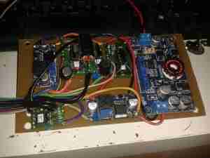
All of the parts I required to complete the supply arrived this morning. After several hours of building, here’s what I came up with:

I’ve mounted everything on a piece of FR4 PCB, with it’s copper plane grounded to the case. This backing board is the same size as the original PSU PCB to allow it to be screwed into the same location in the scope.
The power comes in via the converter on the right, which outputs a single 24v rail for the rest of the supplies. The other 6 supplies then generate the individual voltage rails that the scope requires. The use of a single input supply allows this system to operate at voltages up to 30v DC, so it’s good for both 12v & 24v systems.

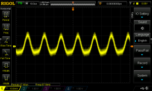
At present the only issue is with some ripple on one of the supplies, this is showing up on the scope display with no input connected at the lowest volts/division. Parts are on order from Farnell to build some common mode filters to remove this from the DC output.
On a 13.8v supply, the scope draws about 1.5A total from the supply, giving a total power consumption of 20.7W. This is with all 4 channels enabled.
My wiring assignments & DC-DC converter ratings are in the table below
| Connector Pin | PCB Pin | Signal | Mainboard | DC-DC Rating | Wire Colour |
|---|---|---|---|---|---|
| 1 | 10 | GND | GND | N/A | BLACK |
| 2 | 2 | +9v_GND | FAN -- | NA | BLACK |
| 3 | 8 | +7.5V | 6.3V | 6A | ORANGE |
| 4 | 14 | -7.5V | -7.5V | 2A | GREEN |
| 5 | 1 | NOT USED | AC_TRIG | N/A | NOT USED |
| 6 | 4 | +5V | 5V5A | 6A | RED |
| 7 | 6 | GND | GND | N/A | BLACK |
| 8 | 7 | GND | GND | N/A | BLACK |
| 9 | 12 | -17.5V | -17.5V | 3A | PURPLE |
| 10 | 9 | +7.5V | 6.3V | 6A | ORANGE |
| 11 | 3 | +9V | FAN + | 1A | GREY |
| 12 | 11 | 17.5V | 17.5V | 3A | BLUE |
| 13 | 5 | +5V | 5V5A | 6A | RED |
| 14 | 13 | GND | GND | N/A | BLACK |
Stay tuned for the final section of this build with the power supply filtering & main DC input connections!
73s for now 🙂
