I did a little more digging into the PSU circuitry of the small coin counting machine, and it’s even more strange than I thought!
The part I originally thought was a transformer on the PSU board is in fact a DC-DC converter module!
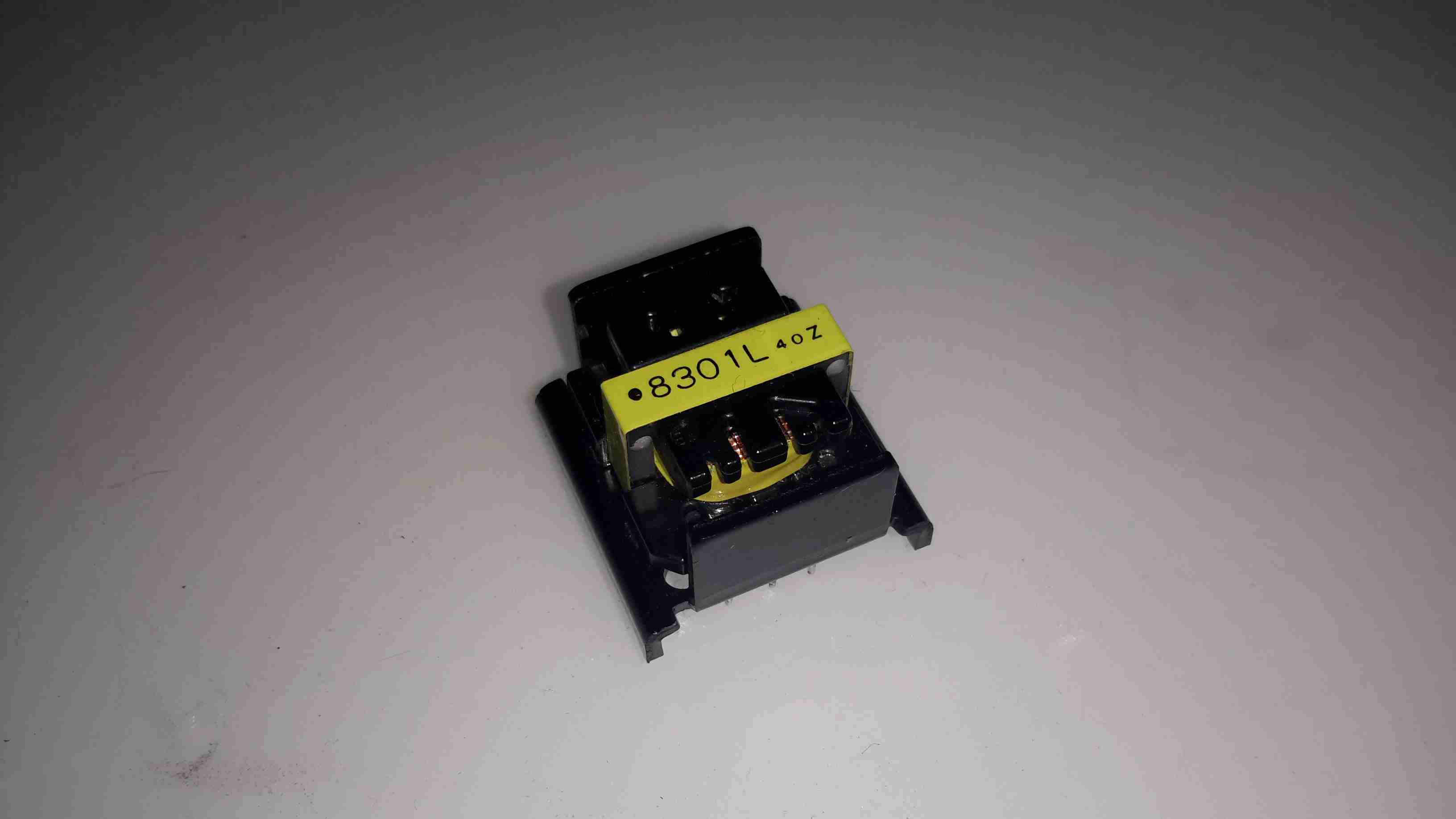
Here’s the device after desoldering it from the PCB. It turns out that instead of a transformer, it’s an inductor.
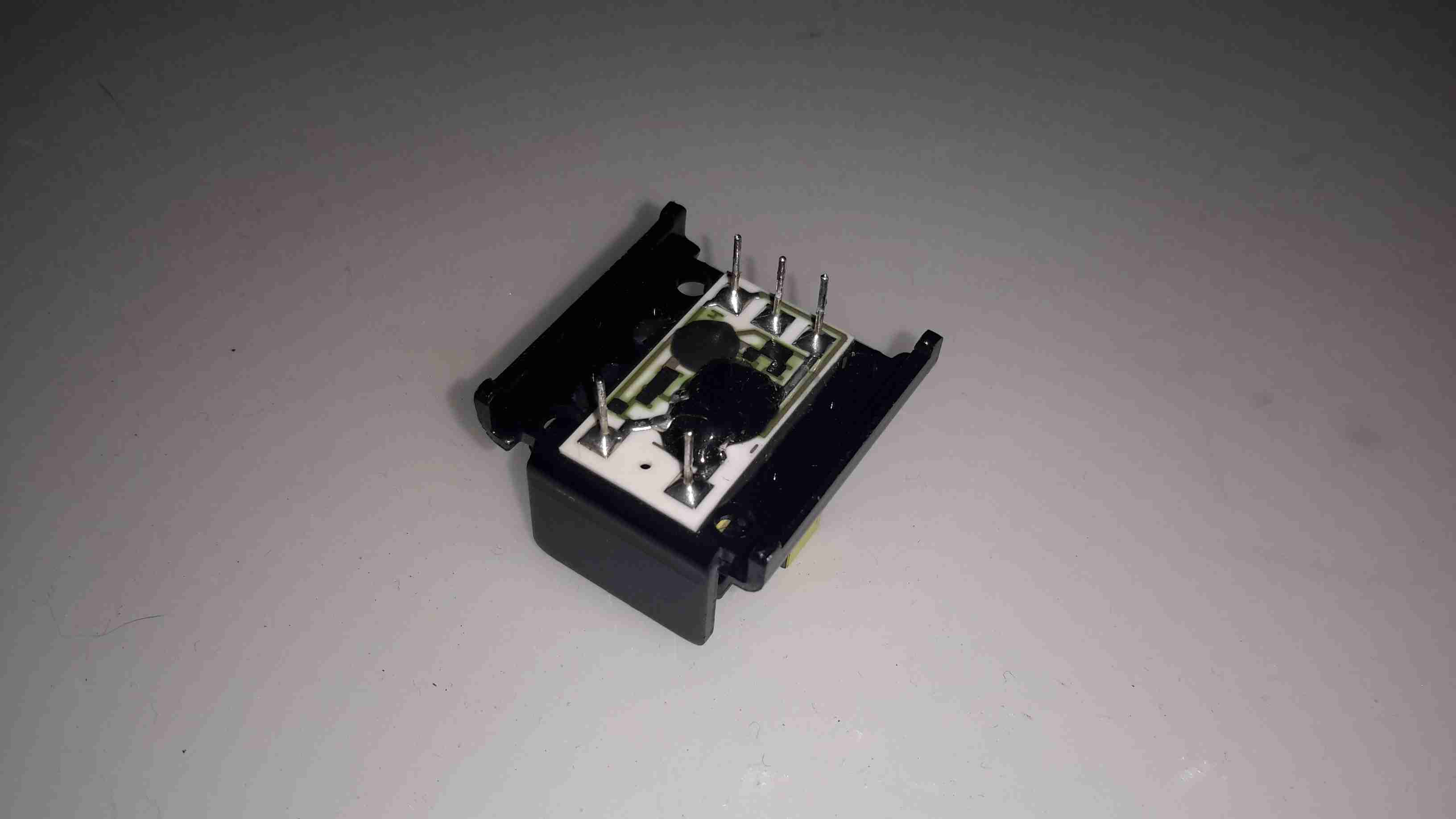
Underneath is the controller electronics, with an COB controller & the switching transistors are under a protective covering of silicone.
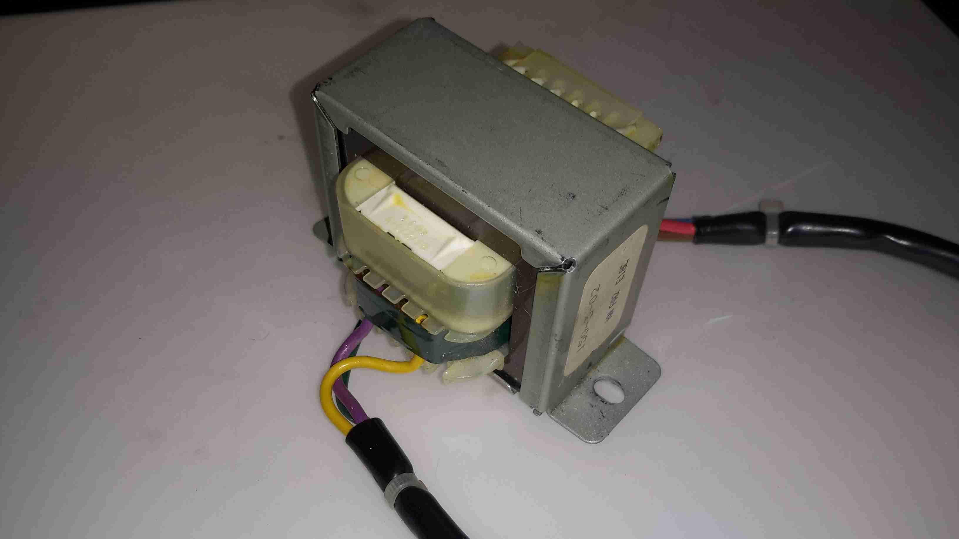
Driving this whole lot of PSU randomness is the mains transformer, with a secondary voltage of 35v.
The only reason I can think of that the manufacturer went to this much expense with the power supply is stability – a coin counting machine that miscounts due to power supply surges, sags & spikes wouldn’t be very much use. It’s not likely I’ll see anything similar again, unless I manage to get hold of something like medical grade equipment.
