Posted on 4 Comments

Sentora 1.0.3 SpamAssassin Setup & Training Scripts

I’m making some changes to my hosting services, I’ve been testing Sentora, as it’s much more user friendly, if a little more limited in what it’s capable of doing, vs my go-to admin panel over the past 6+ years, Virtualmin.

I noticed that SpamAssassin isn’t set up on a Sentora server by default, so here’s a script that will get things working under a fresh Sentora install in CentOS 7:

#!/bin/bash

echo "Setting Up SpamAssassin. Please Wait..."

yum install spamassassin -y
groupadd spamd
useradd -g spamd -s /bin/false -d /var/log/spamassassin spamd
chown spamd:spamd /var/log/spamassassin

echo "Changing Postfix Master Config For SA..."
echo "master.cf Backed Up to /root"

cp /etc/postfix/master.cf /root/postfix_master.cf.bak
sed -i '11s/.*/smtp      inet  n       -       n       -       -       smtpd -o content_filter=spamassassin/' /etc/postfix/master.cf
echo "spamassassin unix - n n - - pipe flags=R user=spamd argv=/usr/bin/spamc -e /usr/sbin/sendmail -oi -f \${sender} \${recipient}" >> /etc/postfix/master.cf

echo "Updating SpamAssassin Database & Enabling Services..."
sa-update --nogpg
systemctl enable spamassassin
systemctl restart spamassassin
systemctl restart postfix

After this script has run, some mail server settings will be changed, and the master.cf configuration file for Postfix will be backed up just in case it craps out.

Make sure the SpamAssassin daemon is running on port 783 with this command:

ss -tnlp | grep spamd

Testing is easy, send an email to an address hosted by Sentora with the following in the subject line:

XJS*C4JDBQADN1.NSBN3*2IDNEN*GTUBE-STANDARD-ANTI-UBE-TEST-EMAIL*C.34X

If SpamAssassin is working correctly, this will be tagged with a spam score of 999.

A useful script is below, this trains SpamAssassin on the mail in the current server mailboxes. I’ve been using a version of this for a long time, this one is slightly modified to operate with Sentora’s vmail system. All mail for all domains & users will be fed into SpamAssassin in this script. I set this to run nightly in cron.

#!/bin/bash

#specify one or more users, space padded [user=(user1 user2 user3)] or empty [user=()] to include all users. All users is considered uid ≥ 1000.
user=(vmail)

#After how many days should Spam be deleted?
cleanafter=30

#backup path, comment out to disable backups
bk=/home/backup/sa-learn_bayes_`date +%F`.backup

log=/var/log/train-mail.log
#log=/dev/stdout

echo -e "\n`date +%c`"  >> $log 2>&1

if [ -z ${user[@]} ]; then
echo user is empty, using all users from system
user=(`awk -F':' '$3 >= 1000 && $3 < 65534' /etc/passwd |awk -F':' '{print $1}'`)
fi

for u in ${user[@]}; do
if [ ! -d /var/sentora/vmail/*/* ]; then
echo "No such Maildir for $u" >> $log 2>&1
else
echo "Proceeding with ham and spam training on user \"$u\""
#add all messages in "junk" directory to spamassassin
echo spam >> $log 2>&1
#change this path to match your spam directory, in this case its "Junk"
#add current and new messages in Junk directory as spam
sa-learn --no-sync --spam /var/sentora/vmail/*/*/.Junk/{cur,new} >> $log 2>&1
echo ham >> $log 2>&1
#only add current mail to ham, not new. This gives user a chance to move it to spam dir.
sa-learn --no-sync --ham /var/sentora/vmail/*/*/{cur} >> $log 2>&1
fi
done

#sync the journal created above with the database
echo sync >> $log 2>&1
sa-learn --sync >> $log 2>&1
if [ $? -eq 0 ]; then
for u in ${user[@]}; do
echo "deleting spam for $u older than 30 days" >> $log 2>&1
find /var/sentora/vmail/*/*/.Junk/cur/ -type f -mtime +$cleanafter -exec rm {} \;
done
else
echo "sa-learn wasn't able to sync. Something is broken. Skipping spam cleanup"
fi

echo "Statistics:" >> $log 2>&1
sa-learn --dump magic >> $log 2>&1
echo ============================== >> $log 2>&1

if [ -n $bk ]; then
echo "backup writing to $bk" >> $log 2>&1
sa-learn --backup > $bk
fi
 

Posted on Leave a comment

Philips LED PAR38 Lamp Teardown

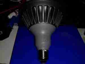
Philips PAR38
Philips PAR38

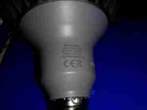
These large LED Philips PAR38 lamps were recently on clearance sale in my local T.N. Robinsons electrical contractors for about £3, so I decided to grab one in the hopes I might be able to hack it into a low-voltage LED lamp. These are full-size PAR38 format, with most of the bulk being the large aluminium heatsink on the front. The back section with the power supply module is secured with silicone, so some unreasonable force was required to liberate the two pieces.

Specification
Specification

These lamps are rated at 18W in operation, and are surprisingly bright for this power level.

Lens
Lens

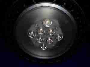
The front has the moulded multi-lens over the LEDs, to spread the light a bit further than the bare dies.

LED Array
LED Array

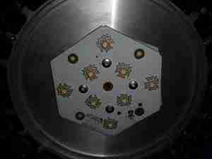
The LED array is two series strings of 4 LEDs, for ~24v forward voltage. Unusual for a high power LED array, this PCB isn’t aluminium cored, but 0.8mm FR4. Heat is transferred to the copper plane on the backside by the dozens of vias around the Luxeon Rebel LEDs. There is a thermal pad under the PCB for improved heat transfer to the machined surface of the heatsink.

Control PCB Top
Control PCB Top

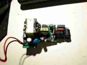
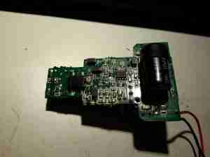
The power supply & control PCB is pretty well made, it’s an isolated converter, so no nasty mains on the LED connections.

Control PCB Bottom
Control PCB Bottom
Posted on 4 Comments

Virgin Media Hub 3 Crap & Router Upgrades

I posted a while back a teardown of the VM Superhub 2 router, as VM has “upgraded” to a rebranded Arris TG2492S/CE CM. Alas Virgin Media in their wisdom have decided that simple router features like being able to change the LAN subnet & DHCP server range are far too complex to trust to the Great Unwashed, so they’ve removed them entirely from the firmware, and locked the local LAN onto the 192.168.0.0/24 range.
As my network is already numbered in the 10.0.0.0/16 range, with several statically addressed devices present and other systems relying on these static assignments, using this router would have meant renumbering everything.

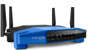
Luckily Virgin had the decency to leave the “modem mode” option in the firmware, effectively disabling the WiFi & routing functions & allowing the connection of a third-party router. Some searching for a suitable replacement for the core of my network turned up the Linksys WRT1900ACS. While I waited for this to arrive, some temporary workarounds were needed to make everything function well enough with VM’s crap router.
WRT1900ACS
WRT1900ACS

These routers have been designed as a modern replacement for the venerable WRT54G series of routers from some time ago, with full support for OpenWRT/DD-WRT firmware, and with a beefy 1.6GHz dual core CPU & 512MB of RAM I doubt I’ll be able to knock this one over with too much network traffic! This was pretty much the most powerful router I could afford, and should mean I don’t need to upgrade for a long time. (No teardown of this yet, as it’s taking care of the network at present. Maybe some point in the future I’ll take the plunge).

The stock firmware isn’t totally awful, and has some nice features, but I decided it needed to be replaced with DD-WRT for more security & future flexibility. I’ll leave the firmware flashing stuff for another post 😉

Posted on Leave a comment

Bargain Bin USB-ODB Interface

ODB Adaptor
ODB Adaptor

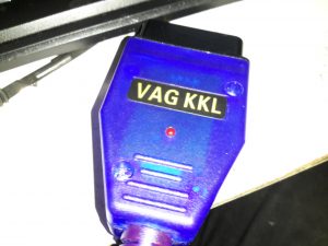
This is a little bit of kit I got to talk to the Webasto TT-V I salvaged from a scrap Jaguar S-Type, and converts USB-RS232 to the standard car diagnostic ODB connector. (These are a much cheaper option at £4 than the official Webasto diagnostic adaptor & loom which is over £90.

PCB Top
PCB Top

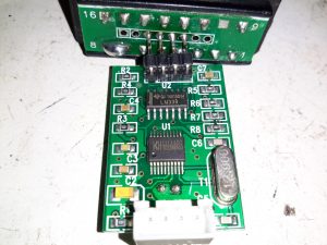
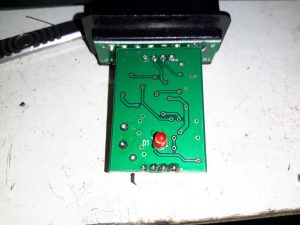
There’s really not much to this adaptor, the only signals that are routed to the ODB connector seem to be the +12v on pin 16, K-Line on Pin 7 & L-Line on pin 15. The main IC here is a CH340 USB-Serial interface, with some glue logic in the form of an LM339 quad comparator.

PCB Reverse
PCB Reverse

The reverse side of the PCB only has the power indicator LED.

Posted on 11 Comments

Jaguar S-Type Aux Heater / Webasto Thermo Top V Part 2 – W-Bus Diagnostics

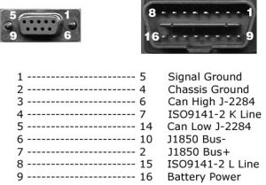
As I mentioned in the previous post, these heaters have a standard interface that’s used for control & diagnostics, the W-Bus. This is transmitted over the K-Line of the vehicle bus, and all heaters, regardless of firmware modifications done by the various car manufacturers respond to this interface. Official Webasto diagnostic adaptors are available, but these are just a very expensive serial adaptor. A much cheaper option is a ~£5 Universal ODB adaptor.

ODB2
ODB2

Above shows the signals on the ODB connector – the ones we’re interested in here are Pin 16, the +12v supply, and Pin 7, K-Line. Connect Pin 16 to the positive supply to the heater, and Pin 7 to Pin 2 on the Webasto heater. (Valid for all TT-V heaters).

Device Selection
Device Selection

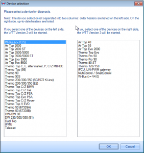
Once these two connections are made to the heater, fire up the Thermo Test software. The screen above will be displayed. Pick W-Bus at top left.

COM Port Selection
COM Port Selection

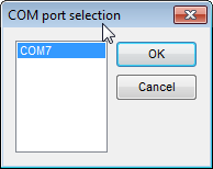
First thing, connect the ODB adaptor to USB, and change to the correct COM port in Thermo Test. There may be several in the list, but a newly connected USB device should show up with the highest COM number.

Thermo Test
Thermo Test

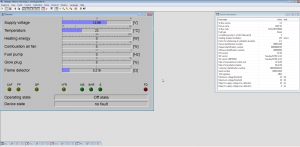
Once Thermo Test is running, start communications by going to the Diagnosis Menu > Start Diagnostic (F2 keyboard shortcut).

Initialized
Initialized

After a few seconds, communication will be established. This will show faults, if any are present, and allow testing of the heater & it’s component parts. A summary report can be generated with Diagnosis > View Summary:

Diagnosis report                                               Webasto Thermosystems
------------------------------------------------------------------------------------------


Configuration:
--------------
  W-Bus version...............................................................3.3           
  Device name.............................................................X204 SH           
  W-Bus code.......................................................715CC0E73F8000           
  Fuel type................................................................Diesel           
  Circulating pump in control idle period.......................................0           
  Heating duration limitation.................................................255 [min]     
  Factor for shortening of ventilation duration...............................1/1           
  Device identification number..........................................09007236E           
  Dataset identification number.......................................09006806H05           
  Software identification number........................................000000000           
  HW version................................................................51/03           
  SW version..................................................Tuesday/07/04 12.12           
  SW version (EEPROM).........................................Tuesday/07/04 12.12           
  Date of manufacture control unit.......................................27.10.03           
  Date of manufacture heater.............................................04.02.04           
  Customer identification number.....................................4R8318K463AE           
  Serial number........................................................0000123626           
  Test signature.............................................................4B42           
  Minimum voltage threshold....................................................10 [V]       
  Maximum voltage threshold....................................................16 [V]       
  Delay for supply voltage min. detection......................................20 [s]       
  Delay for supply voltage max. detection.......................................6 [s]       

Operating data:
---------------
  Working hours.............................................................44:03 [h:m]     
  Operating hours.........................................................5388:08 [h:m]     
  Start count...............................................................19129           
  Burning duration PH 1..33%.................................................0:00 [h:m]     
  Burning duration PH 34..66%................................................0:00 [h:m]     
  Burning duration PH 67..100%...............................................0:00 [h:m]     
  Burning duration PH >100%..................................................0:00 [h:m]     
  Burning duration SH 1..33%.................................................0:00 [h:m]     
  Burning duration SH 34..66%................................................0:00 [h:m]     
  Burning duration SH 67..100%...............................................0:00 [h:m]     
  Burning duration SH >100%..................................................0:00 [h:m]     
  Working duration PH........................................................0:51 [h:m]     
  Working duration SH......................................................121:10 [h:m]     
  Start counter PH..............................................................6           
  Start counter SH............................................................854           
  Ventilation duration.......................................................0:00 [h:m]     

Error:
------

------------------------------------------------------------------------------------------
12.03.17  17:17:30                                       Webasto Thermo Test  2.16.1

This shows all the important stuff, including running hours. (5388Hrs on this heater!). Most importantly, there are no faults listed.

Heater Running
Heater Running

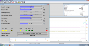
The heater can be fully tested by issuing a start command from the Command Menu > Parking Heating option. Obviously cooling water will be required for this, along with an external water pump. (The water pump control output on these heaters seems to be totally disabled in firmware, as they rely on the engine’s coolant pump). I used a bucket of water along with a small centrifugal pump to provide the cooling. During this test I noted that the firmware is much more aggressive in these units. The marine versions shut down at ~72°C water temperature, whereas these don’t so the same until ~90°C.

Now I’ve managed to communicate with the heater, I’ll get onto building a standalone controller so I can dispense with the Windows VM for control.

Posted on 5 Comments

Jaguar S-Type Aux Heater / Webasto Thermo Top V Part 1 – Teardown & Cleaning

Jag Label
Jag Label

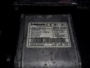
Here’s another Diesel-fired heater related project – these Webasto heaters are fitted to Jaguar S-Type cars as auxiliary heaters, since (according to the Jag manual), the modern fuel-efficient diesels produce so little waste heat that extra help is required to run the car’s climate control system. (Although this seems to nullify any fuel efficiency boost, as the fuel saved by not producing so much waste heat in the engine itself is burned in an aux heater to provide heat anyway). The unfortunate part is these units don’t respond to applying +12v to Pin 1 of the ECU to get them to start – they are programmed to respond to CAN Bus & K-Line Bus only, so they require a bit more effort to get going. They also don’t have a built-in water circulation pump unlike the Webasto Thermo Top C heaters – they expect the water flow to be taken care of by the engine’s coolant pump.

Webasto Label
Webasto Label
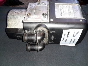
Water Side
Water Side

The water ports are on the side of this heater instead of the end, the heat exhanger is on the left. These hearers are fitted to the car under the left front wing, behind a splash guard. Pretty easy to get to but they get exposed to all the road dirt, water & salt so corrosion is a little problem. The fuel dosing pump is in a much more difficult spot to get at – it’s under the car next to the fuel tank on the right hand side. Access to the underside with stands is required to get at this.

ECU Side
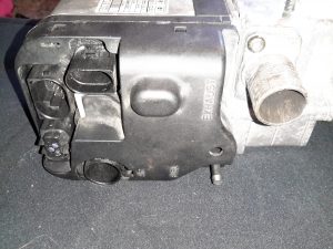
ECU Side

The ECU side has all the other connections – Combustion air, exhaust, fuel, power & control.

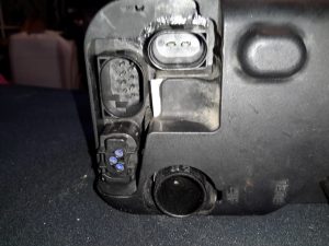
External Connectors
External Connectors

Only two of the external connectors are used on these heaters, the large two pin one is for main power – heavy cable required here as the current draw can climb to ~30A on startup while the glow plug fires. The 8-pin connector on the left is the control connector, where the CAN / K-Line / W-Bus buses live. The fuel dosing pump is also supplied from a pin on this connector. The small 3-pin under that is a blank for a circulation pump where fitted. Pinouts are here:

PinSignal
1Battery Positive
2Battery Negative
Pin NumberSignalNotes
1Telestart / Heater EnableWould usually start the heater with a simple +12v ON signal, but is disabled in these heaters.
2W-Bus / K-LineDiagnostic Serial Bus Or Webasto Type 1533 Programmer / Clock
3External Temp Sensor
4CAN-CAN Bus Low
5Fuel Dosing PumpFuel Pump output. Connect pump to this pin & ground. Polarity unimportant.
6Solenoid ValveFuel cutoff solenoid optionally fitted here.
7CAN+CAN Bus High
8Cabin Heater Fan ControlThis output switches on when heater reaches +50°C to control car heater blower
PinSignalNotes
1??
2Circulation Pump +
3Circulation Pump -
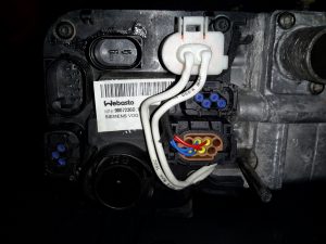
ECU Cover Removed
ECU Cover Removed

Removing the clipped-on plastic cover reveals the other ECU connectors. The large white one feeds the glow plug, & the large multi-pin below brings in the temp & overheat sensor signals.

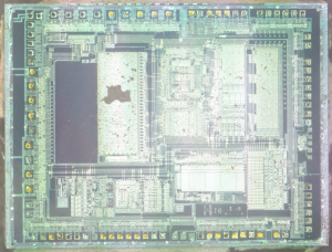
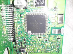
MC9S12DT128B Microcontroller

The heart of the ECU is a massive microcontroller, a Freescale MC9S12DT128B, attached to a daughterboard hooked into the ECU power board.

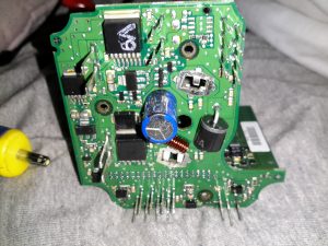
Power Section
Power Section

The high power section is on the board just under the connectors, here all the large semiconductors live for switching the fan motor, glow plug, external loads, etc.

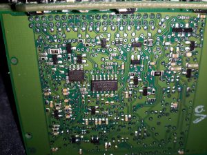
LIN & CAN Bus Transceivers

The bus transceivers are separate ICs on the control board, a TJA1041 takes care of the CAN bus. There’s also a TJA1020 LIN bus transceiver here, which is confusing since none of the Webasto documentation mentions LIN bus control.

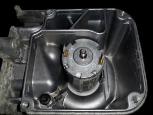
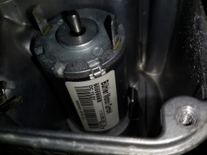
Combustion Fan Motor

The combustion fan motor is in the ECU compartment, nicely sealed away from the elements. There is no speed sensor on these blowers, unlike the Eberspacher ones.

Motor Details
Motor Details

The motor is a Buhler, rated at 10.5v.

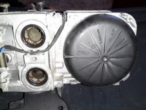
Water Ports & Combustion Fan Cover

Unclipping the cover from the other end reveals the combustion fan, it’s under the black cover. (These are side-channel blowers, to provide the relatively high static pressure required to run the burner).

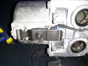
Sensor Clip
Sensor Clip

The overheat & temperature sensors are on the end of the heat exchanger, retained by a stainless clip.

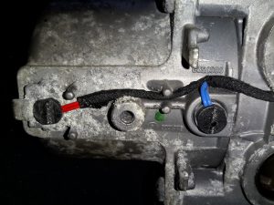
Temp & Overheat Sensors

With the clip removed, the sensors can be seen better. There’s some pretty bad corrosion of the aluminium alloy on the end sensor, it’s seized in place.

Burner
Burner

The heater splits in half to reveal the evaporative burner itself. I’ve already cleaned the black crud off with a wire brush here, doesn’t look like this heater has seen much use as it’s pretty clean inside.

Burner Chamber
Burner Chamber

Inside the burner the fuel evaporates & is ignited. There is a brass mesh behind the backplate of the burner to assist with vaporisation.

Glow Plug
Glow Plug

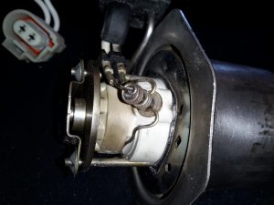
The glow plug is fitted into the side of the burner ceramic here. This is probably a Silicon Carbide device. It also acts as a flame sensor when the heater has fired up. The fuel inlet line is to the left under the clamp.

Heat Exhanger
Heat Exhanger

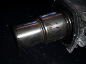
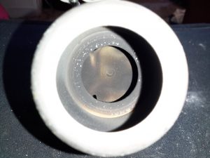
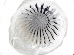
The hot gases from the burner flow into the heat exchanger here, with many fins to increase the surface area. There’s only a couple of mm coating of carbon here, after 10 years on the car I would have expected it to be much more clogged.

I’m currently waiting on some components to build an interface so I can get the Webasto Thermo Test software to talk to the heater. Once this is done I can see if there are any faults logged that need sorting before I can get this heater running, but from the current state it seems to be pretty good visually. More to come once parts arrive!

The full service manual for these heaters can be grabbed from here, along with the wiring details for the Jaguar implementation & the Thermo Test software for talking to them:

[download id=”5618″]

[download id=”5620″]

[download id=”5622″]

Posted on Leave a comment

IC Decap – TDA3606 Multi Regulator With Battery Sense

This is a chip aimed at the automotive market – this is a low power voltage regulator for supplying power to microcontrollers, for instance in a CD player.

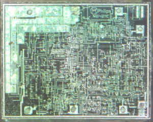
TDA3606 Die
TDA3606 Die

The TDA3606 is a voltage regulator intended to supply a microprocessor (e.g. in car radio applications). Because of low voltage operation of the application, a low-voltage drop regulator is used in the TDA3606. This regulator will switch on when the supply voltage exceeds 7.5 V for the first time and will switch off again when the output voltage of the regulator drops below 2.4 V. When the regulator is switched on, the RES1  and RES2 outputs (RES2 can only be HIGH when RES1 is HIGH) will go HIGH after a fixed delay time (fixed by an external delay capacitor) to generate a reset to the microprocessor. RES1 will go HIGH by an internal pull-up resistor of 4.7 kΩ, and is used to initialize the microprocessor. RES2 is used to indicate that the regulator output voltage is within its voltage range. This start-up feature is built-in to secure a smooth start-up of the microprocessor at first connection, without uncontrolled switching of the regulator during the start-up sequence. All output pins are fully protected. The regulator is protected against load dump and short-circuit (foldback
current protection). Interfacing with the microprocessor can be accomplished by means of a battery Schmitt-trigger and output buffer (simple full/semi on/off logic applications). The battery output will go HIGH when the battery input voltage exceeds the HIGH threshold level.

Posted on Leave a comment

Topping NX1a Portable Headphone Amplifier

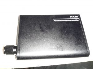
NX1a Amplifier
NX1a Amplifier

Time for another teardown! Here’s a pocket-sized headphone amplifier for use with mobile devices. This unit is powered by a built-in lithium cell, and can give some pretty impressive volume levels given it’s small size.

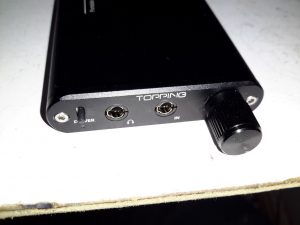
Audio Connections
Audio Connections

The 3.5mm audio input & output jacks are on the front of the unit, along with the relatively enormous volume knob & power switch. There’s a little blue LED under the switch that lets the user know when the power is on, but this is a very sedate LED, using very little power.

Gain & Charging
Gain & Charging

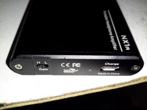
On the back is the High-Low gain switch, and the µUSB charging port. There’s another indicator LED to show that the internal cell is charging, in this case a red one.

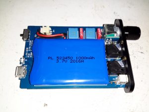
PCB Top
PCB Top

Removing a couple of cap screws allows the internals to slide out of the extruded aluminium casing. Most of the internal space is taken up by the 1Ah lithium cell, here on the top of the PCB secured by some double-sided tape. The volume potentiometer is mounted on a small daughterboard at right angles to get it to fit into the small vertical space in the case.

PCB Rear
PCB Rear

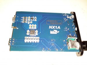
The bottom of the PCB is equally as sparse – the only ICs being the main audio amp in the centre & the battery charger IC at the top.

Amplifier IC
Amplifier IC

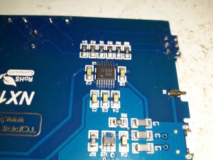
The main audio amplifier is a TP9260, I couldn’t find a datasheet on this, so I’m unsure of what the specs are. The row of resistors above the IC are for the gain divider circuit. There’s also a pogo pin on the right that makes contact with the back panel of the case for grounding.

Battery Charger
Battery Charger

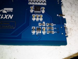
Battery charging is taken care of by a UN8HX 500mA linear charging IC, not much special here.

This little amplifier seems to be pretty well made, considering the price point. The only issue I’ve had so far is the audio cables act like antennas, and when in close proximity to a phone some signal gets picked up & blasted into the headphones as interference.