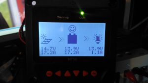
Here’s the MT50 controller from EpEver, that interfaces with it’s Tracer MPPT solar charge controllers, and gives access to more programming options on the charge controllers, without the need for a laptop. The display is a large dot-matrix unit, with built in backlight. Above is the display on the default page, showing power information for the entire system.
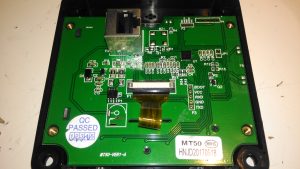
The rear plastic cover is held in place by 4 machine screws, which thread into brass inserts in the plastic frame – nice high quality touch on the design here, no cheap self tapping plastic screws. Both power & data arrive via an Ethernet cable, but the communication here is RS-485, and not compatible with Ethernet! The PCB is pretty sparse, with comms & power on the left, LCD connection in the centre, and the microcontroller on the right.
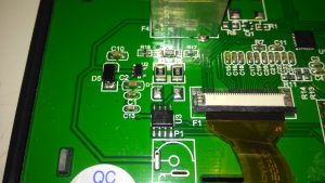
On the left of the board is the RS0485 transceiver, and a small voltage regulator. There’s also a spot for a DC barrel jack, which isn’t included in this model for local power supply.
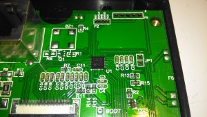
The other side of the board holds the main microcontroller which communicates with the charge controller. This is a STM32F051K8 from ST Microelectronics. With a 48MHz ARM Cortex M0 core, and up to 64K of flash, this is a pretty powerful MCU that has very little to do in this application.
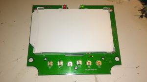
The front of the PCB has the ENIG contacts of the front panel buttons, and the LCD backlight assembly. There’s nothing else under the plastic backlight spreader either.
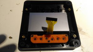
The front case holds the LCD module in place with glue, and the rubber buttons are placed underneath, which is heat staked in place.
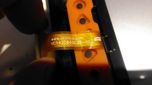
The LCD is a YC1420840CS6 from eCen in China. Couldn’t find much out about this specific LCD.

Thanks for the insights! Is this the old version that just works with the Tracer A models or the newer one that also works with the newer Tracer AN models? As the AN is the common negative/ground model they have changed something with the MT50 models in regards of making it work still being based on the RJ-45 interface providing 5V, Ground, A- and B-signal.
Hi, you was able to reprogram the stm and use the display for other projects?