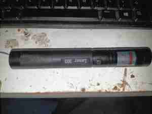
Here’s a cheapo 532nm green laser pointer courtesy of eBay, this one rolled in at £7, with 18650 cell & charger included. Advertised at 1mW, I was immediately suspicious of the output power since this unit quite easily causes skin burns.
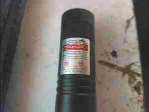
Laser Warning Label
The warning label rates this laser at Class III, with an output power of <1000mW. Massively higher than the 1mW advertised. The end cap is split into two parts that are threaded – the first one is a starfield effect diffraction grating, while the second one moves the final optic to focus the beam.
Starfield Diffraction Grating
The starfield gratings are mounted inside a brass ferrule, which can be rotated to alter the effect without unscrewing from the main body.
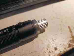
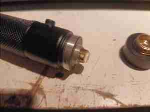
Optics Removed
Removing the output optic barrel reveals the end of the DPSS laser module, which appears to be well glued in. The aluminium cylinder doesn’t appear to have any other purpose other than to protect the laser output end.
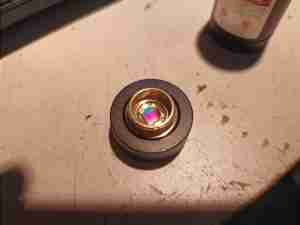
KTP Crystal & Lens
Unscrewing the cylinder reveals the glued holder containing the KTP crystal, and the first output optic. The beam from this alone is very divergent, expanding to ~100mm over a meter or so. The beam right at the optic though is highly focussed & is quite capable of cutting through black electrician’s tape.
There’s also no IR filter anywhere in the optical path – so there is going to be a high power 808nm/1064nm component to the beam since these wavelengths are used in the DPSS process. Since these components are totally invisible, the risk for eye damage is higher due to lack of a blink reflex.
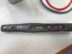
Power Reading
On to the power reading… 351mW of output at 532nm. So quite a bit more than the advertised spec then, but lower than the warning label states. This puts this unit into Class IIIB.
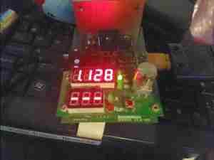
Cell Capacity
From a full charge, down to 2.8v, the “4000mAh” cell provided with this unit managed a pitiful 1128mAh. I knew from the second I got this cell that it would be a fake, since decent 18650 lithium-ion cells cost about the same as this whole package.
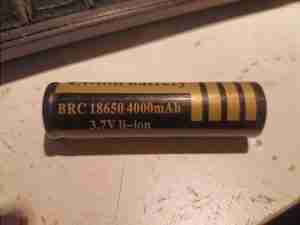
Fake Cell
This cell claims a 4000mAh capacity, and built in protection circuit. Let’s dig under the sleeve…
Nope. No protection circuit here. It’s easy to tell anyway – protected cells are longer, and usually the strap buggering off to the other end of the cell is visible through the sleeve. There is a dual-layer sleeve though, of clear PVC under the BRC branded one. No other markings on the cell at all, and it’s suspiciously light in weight.
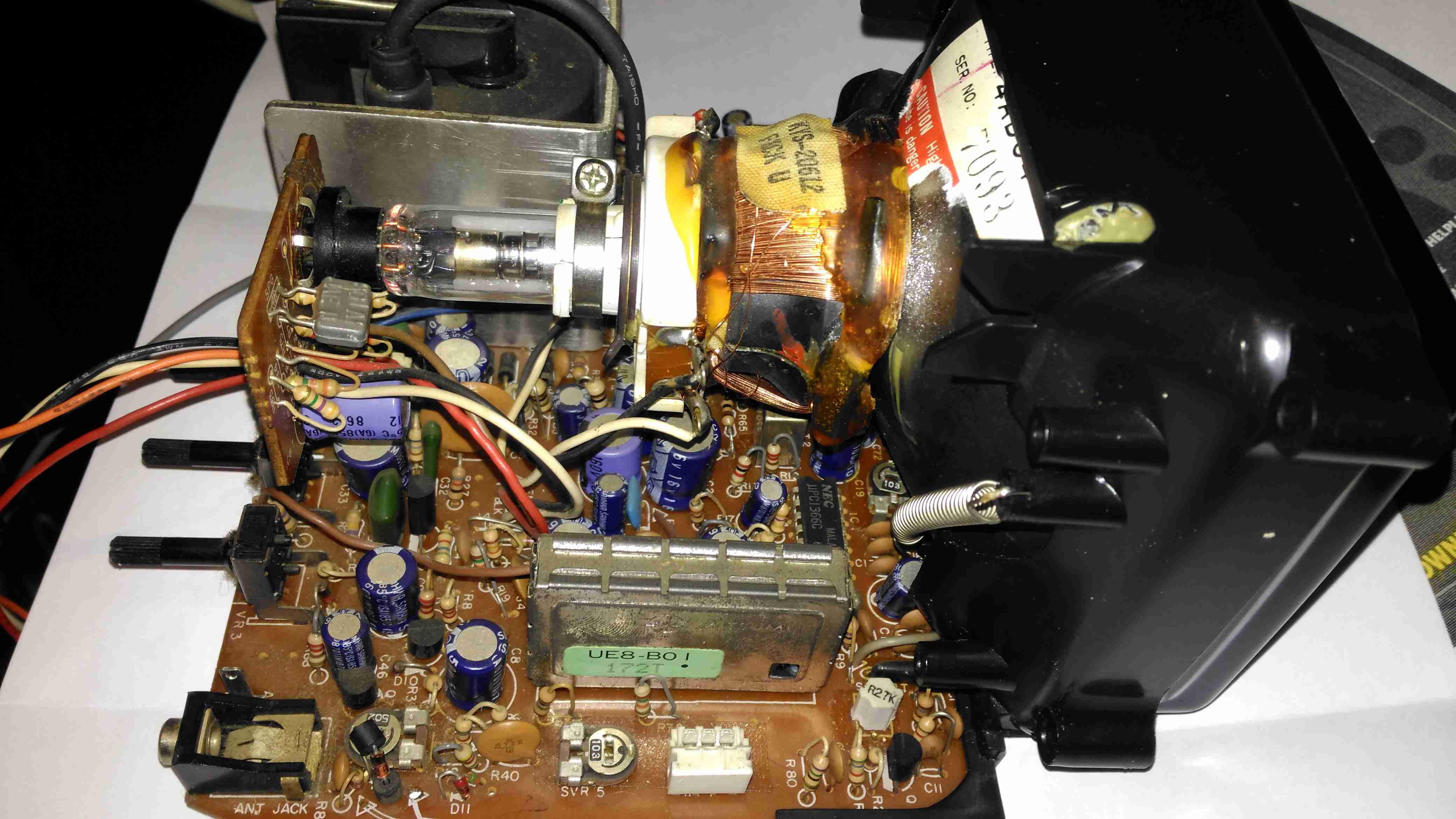
Here’s the CRT & it’s drive board removed from the main chassis. Nicely modular this unit, all the individual modules (radio, tape, TV), are separate. This is effectively a TV itself, all the tuner & IF section are onboard, unlike in other vintage units I’ve modified, where the tuner & IF has been on a separate board. There’s a 3-pin header bottom centre for the tuning potentiometer, and external antenna input jack. The internal coax for the built in antenna has been desoldered from the board here. here a the usual controls on the back for adjusting brightness, contrast & V Hold, all the other adjustments are trimmers on the PCB.
Unfortunately after 30+ years of storage, this didn’t work on first power up, neither of the oscillators for vertical or horizontal deflection would lock onto the incoming signal, but a couple of hours running seemed to improve things greatly. The numerous electrolytic capacitors in this unit were probably in need of some reforming after all this time, although out of all of them, only 21 are anything to do with the CRT itself.
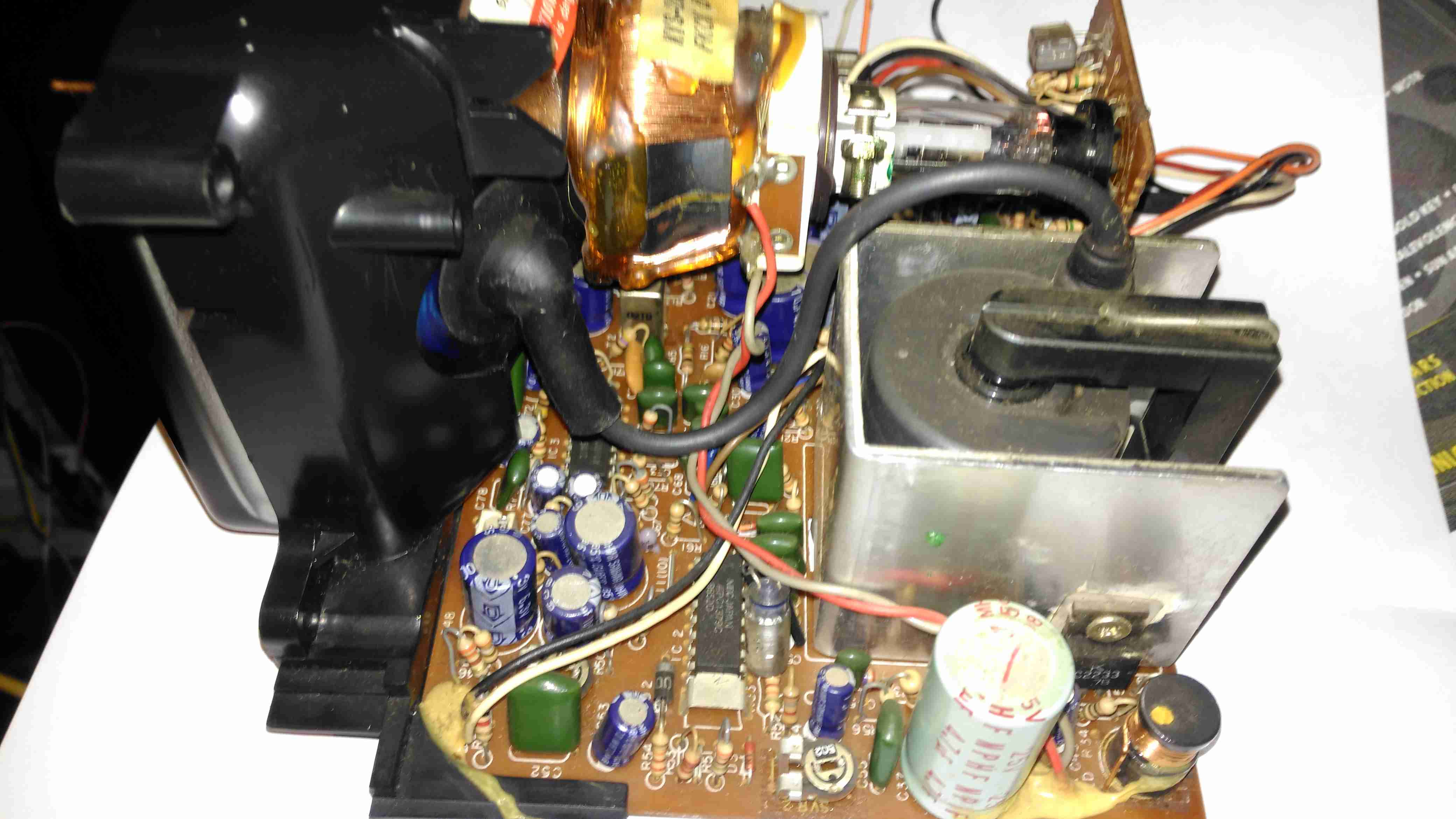
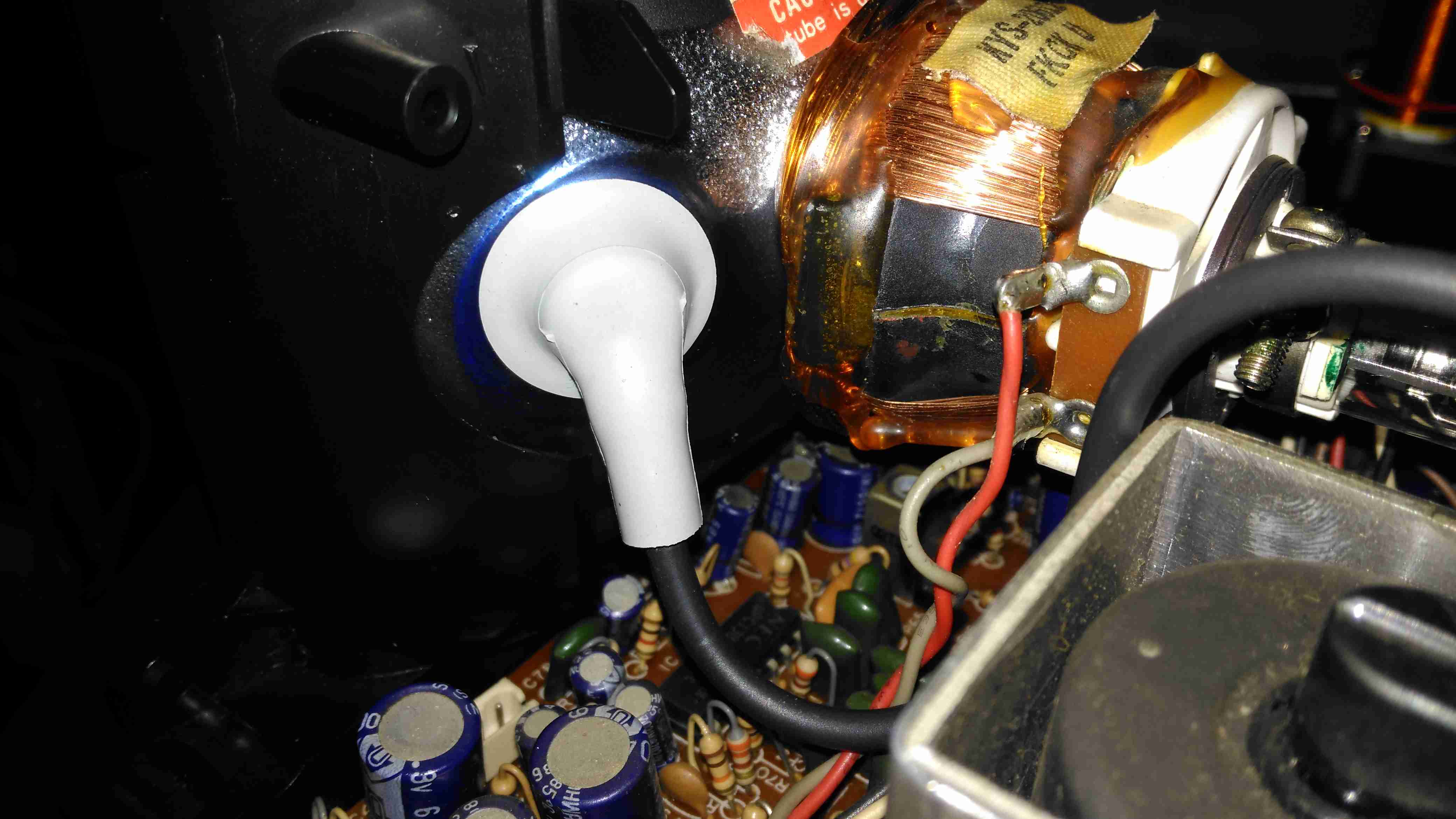
Anode Cap
Here’s the anode side of the unit, with the small flyback transformer. The rubber anode cap has become very hard with age, so I’ll replace this with a decent silicone one from another dead TV. The Horizontal Output Transistor (a 2SC2233 NPN type) & linearity coil are visible at the bottom right corner of the board. Unfortunately, the disgusting yellow glue has been used to secure some of the wiring & large electrolytics, this stuff tends to turn brown with age & become conductive, so it has to be removed. Doing this is a bit of a pain though. It’s still a little bit flexible in places, and rock hard in others. Soaking in acetone softens it up a little & makes it easier to detach from the components.
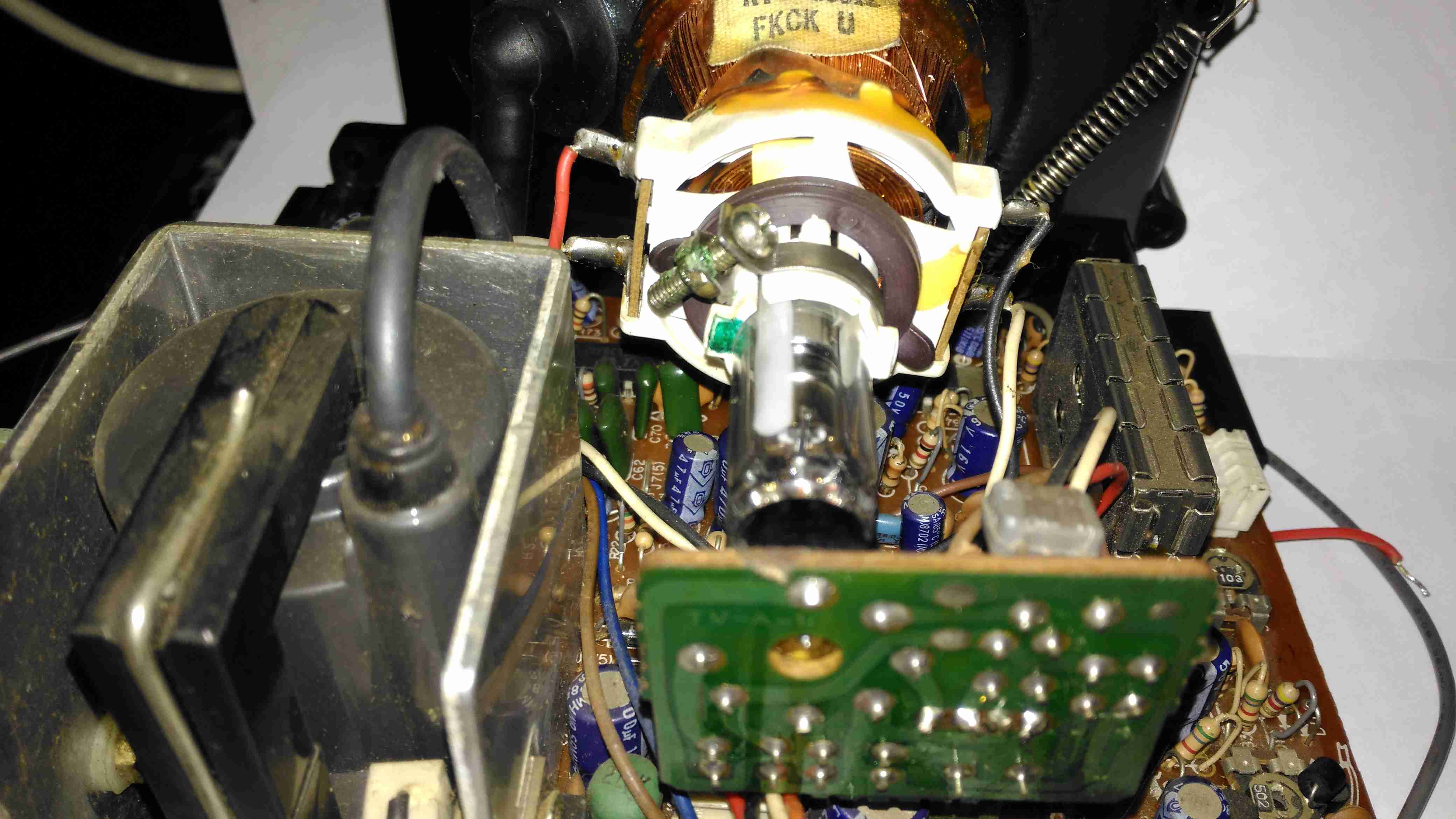
Neck PCB
There’s little on the neck board apart from a few resistors, forming the limiting components for the video signal, and the focus divider of 1MΩ & 470KΩ feeding G3. No adjustable focus on this unit. There’s also a spark gap between the cathode line & ground, to limit the filament to cathode voltage. The flyback transformer is nestled into the heatsink used by the horizontal output transistor & a voltage regulator transistor.
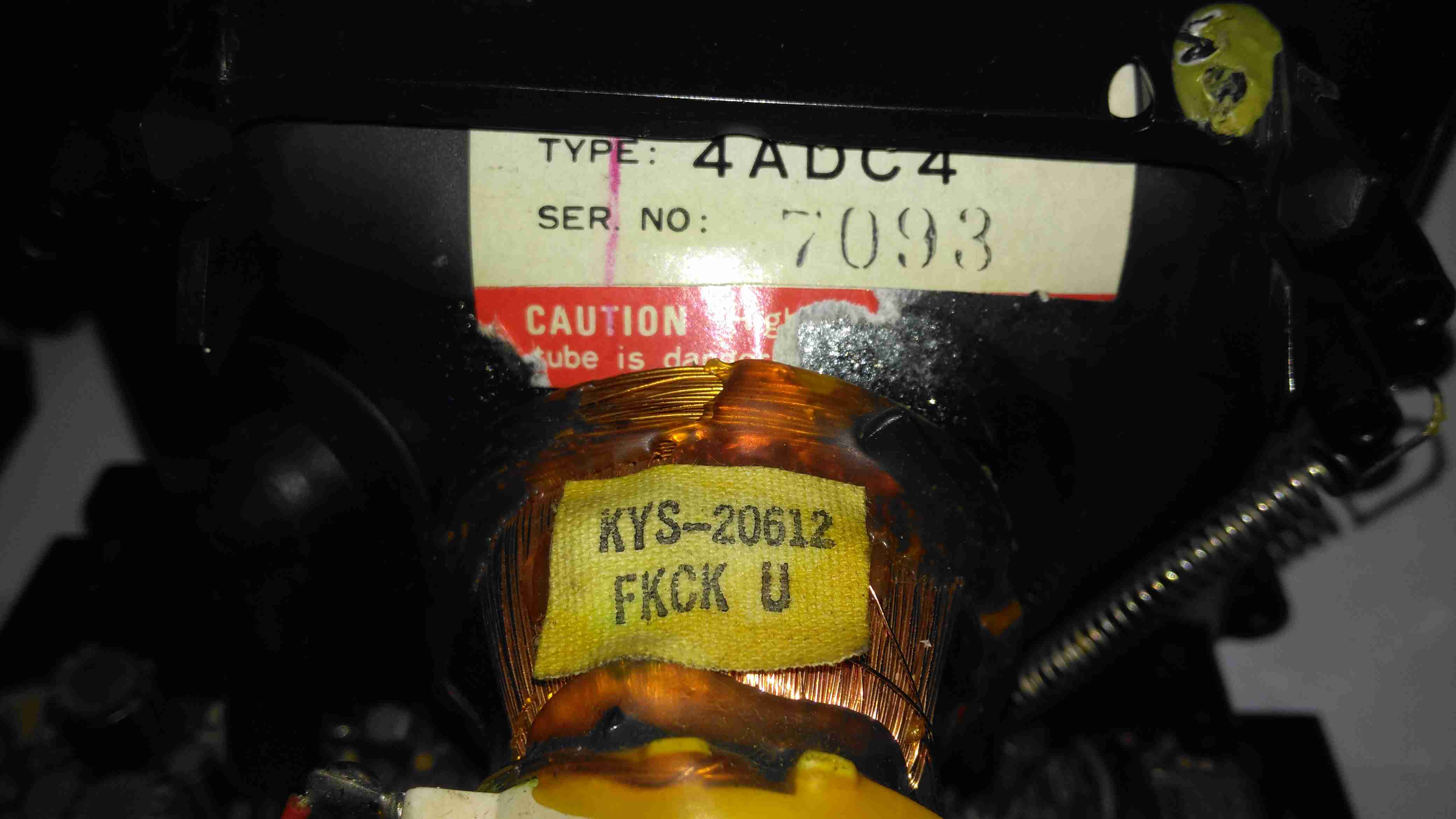
Tube Details
The CRT is a Samsung Electron Devices 4ADC4, with a really wide deflection angle. It’s a fair bit shorter than the Chinese CRT I have which is just a little larger, with a neck tube very thin indeed for the overall tube size.
Unusually, while the filament voltage is derived from the flyback transformer as usual, it’s rectified into DC in this unit, passing through a 1Ω resistor before the filament connection. I measured 5.3v here. The glow from the filament is barely visible even in the dark.
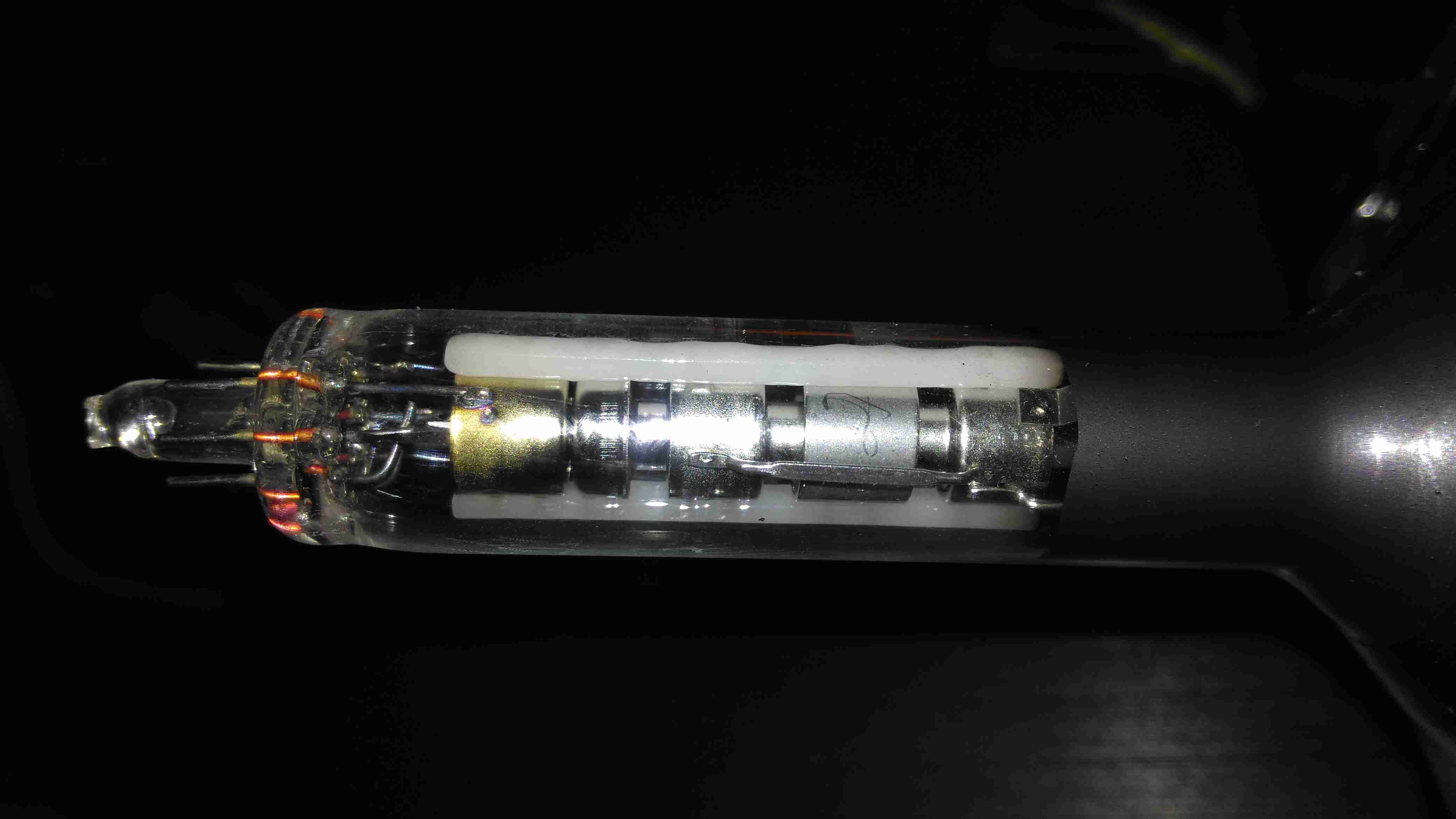
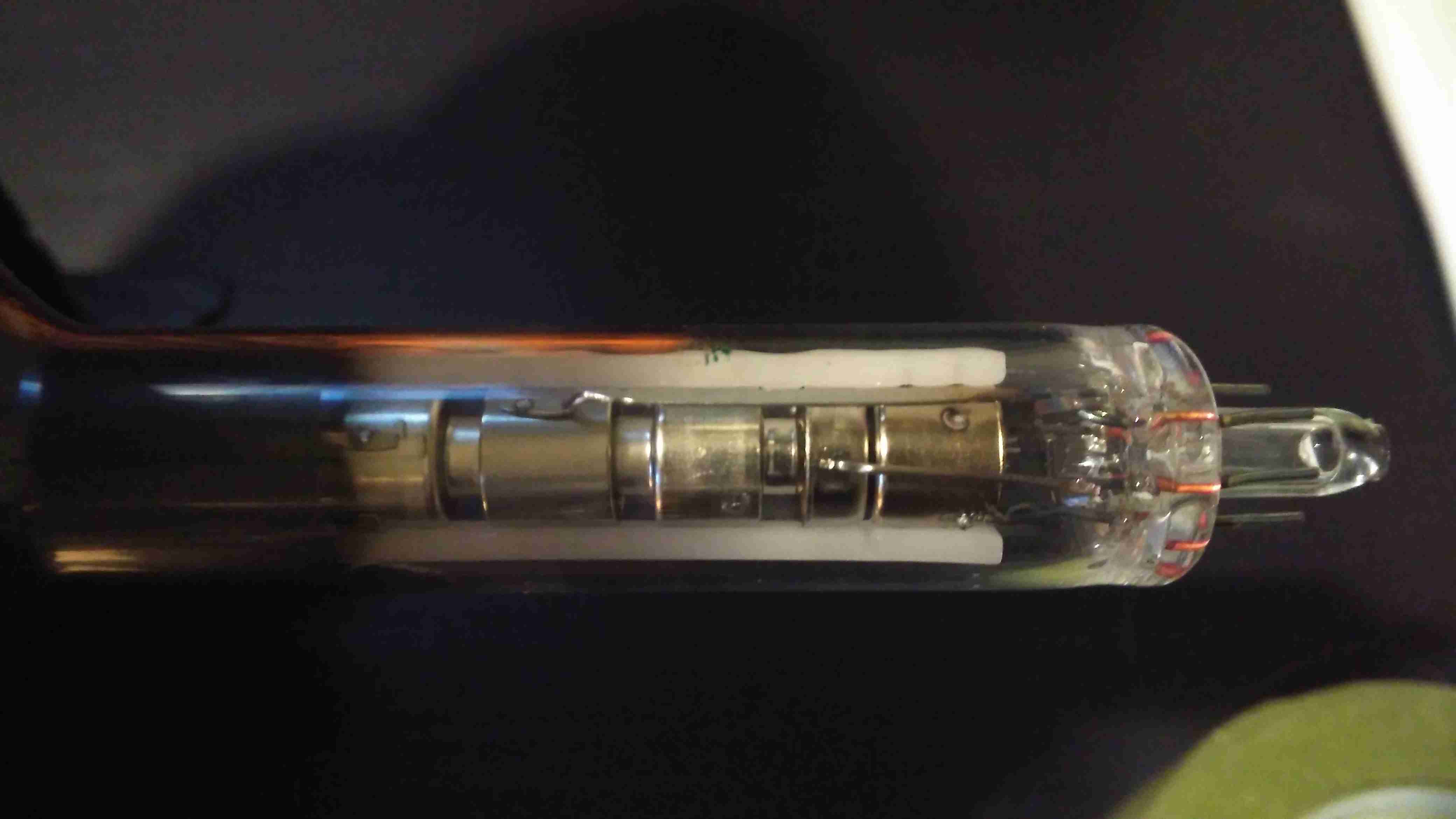
Electron Gun 1
The electron gun is the usual for a monochrome tube, with 7 pins on the seal end.
Electron Gun 2
The electrodes here from left are Final Anode, G3 (Focus Grid), Accelerating Anode, G2 (Screen Grid), G1 (Control Grid). The cathode & filament are hidden inside G1. In operation there’s about 250v on G2, and about 80v on G3.
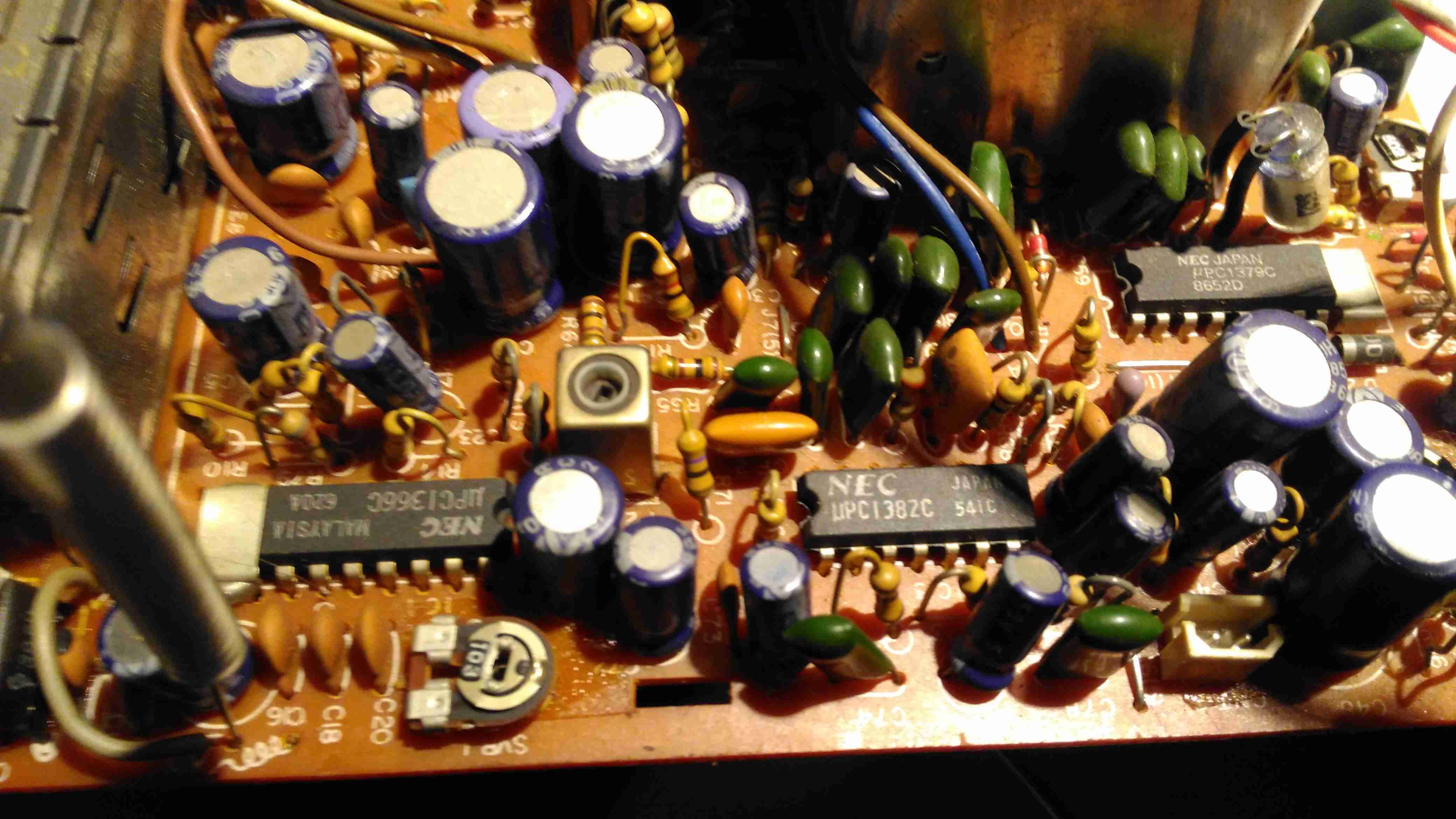
Chipset
The chipset used here is all NEC, starting with a µPC1366C Video IF Processor, which receives the IF signal from the tuner module to the left. This IC outputs the standard composite signal, and a modulated sound signal.
This then splits off to a µPC1382C Sound IF Processor & Attenuator IC, which feeds the resulting sound through the two pin header at the right bottom edge of the board to the audio amplifier in the chassis.
The composite video signal is fed through a discrete video amplifier with a single 2SC2229 transistor before going to the CRT cathode.
The remaining IC is a µPC1379C Sync Signal Processor, containing the sync separator, this is generating the required waveforms to drive the CRT deflection systems from another tap off the composite video line.
From this chip I can assume the unit was built around 1986, since this is the only date code on any of the semiconductors. Besides these 3 ICs, the rest of the circuit is all discrete components, which are well-crammed into the small board space.
There are 5 trimmer potentiometers on the board here, I’ve managed to work out the functions of nearly all of them:
SVR1: IF Gain Adjust
SVR2: H. Hold
SVR3: V. Size
SVR4: B+ Voltage Adjust
SVR5: Tuner Frequency Alignment? It’s in series with the tuning potentiometer in the chassis.
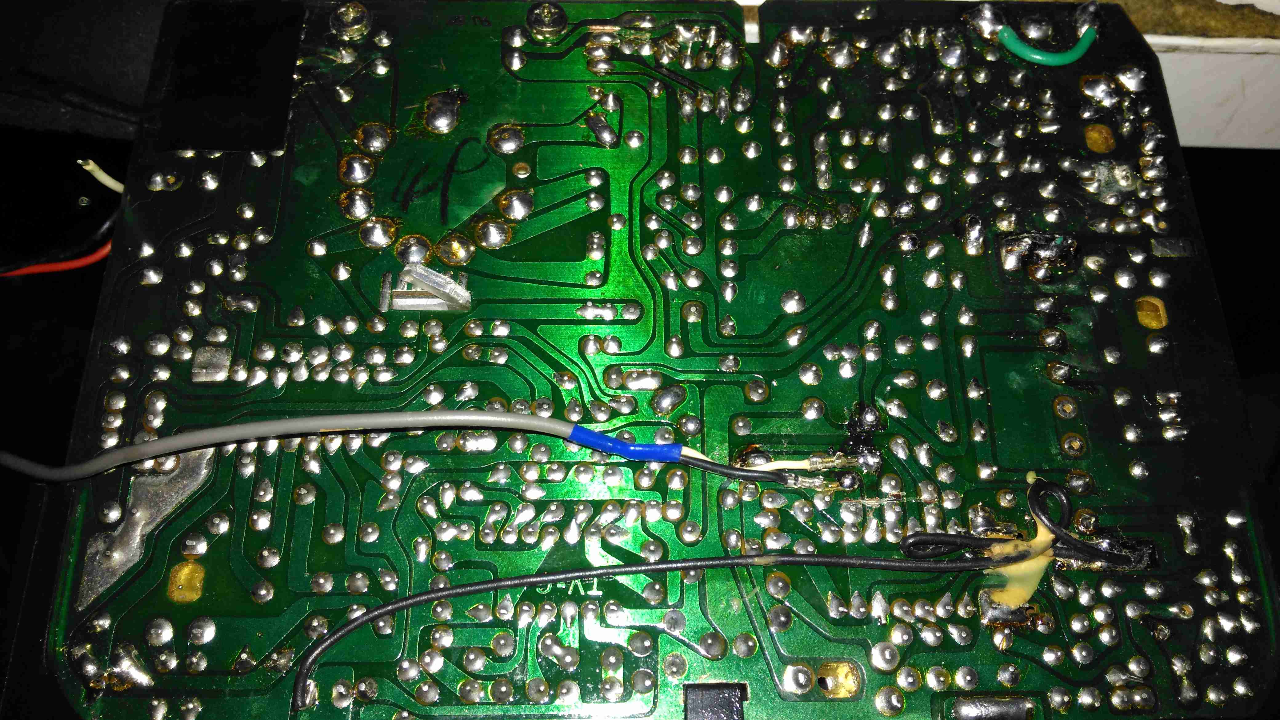
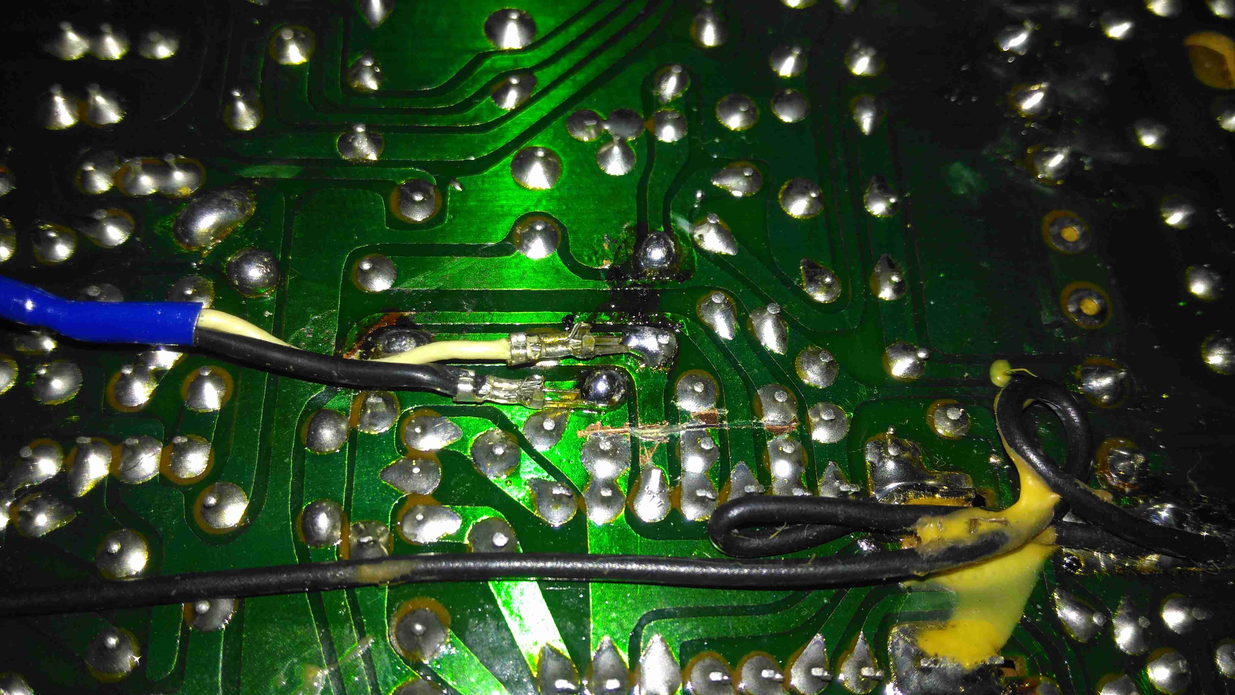
PCB Bottom
The PCB bottom shows the curved track layout typical of a hand taped out board. The soldermask is starting to flake off in places due to age, and there a couple of bodge wires completing a few ground traces. Respinning a board in those days was an expensive deal! Surprisingly, after all this time I’ve found no significant drift in the fixed resistors, but the carbon track potentiometers are drifiting significantly – 10KΩ pots are measuring as low as 8KΩ out of circuit. These will have to be replaced with modern versions, since there are a couple in timing-sensitive places, like the vertical & horizontal oscillator circuits.
Anode Cap Replaced
Here the anode cap has been replaced with a better silicone one from another TV. This should help keep the 6kV on the CRT from making an escape. This was an easy fix – pulling the contact fork out of the cap with it’s HT lead, desoldering the fork & refitting with the new cap in place.
Here I’ve replaced the important trimmers with new ones. Should help stabilize things a little.
Composite Injection Mod
Injecting a video signal is as easy as the other units. Pin 3 of the µPC1366C Video IF Processor is it’s output, so the track to Pin 3 is cut and a coax is soldered into place to feed in an external signal.
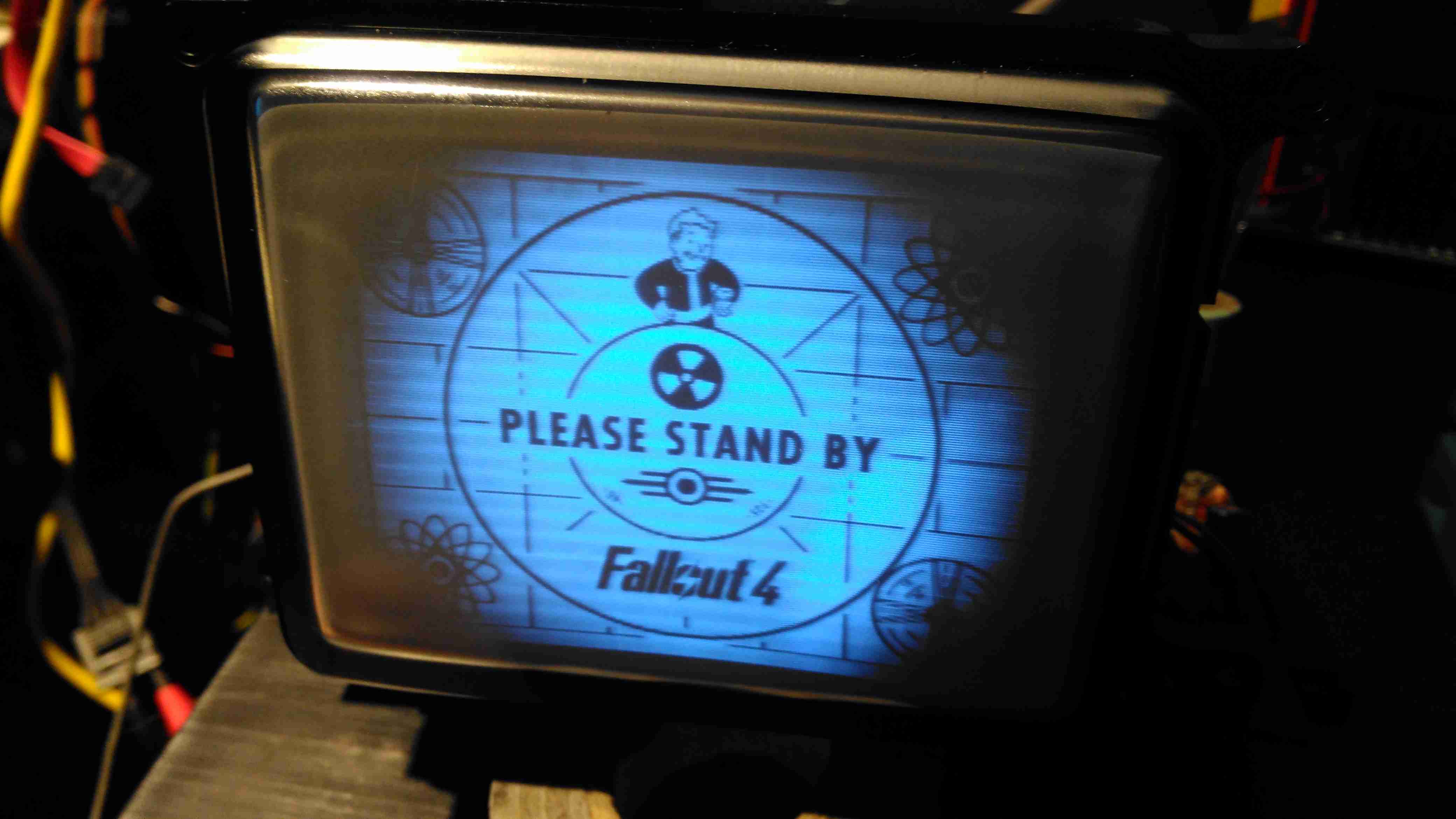
CRT In Operation
After hooking up a Raspberry Pi, we have display! Not bad after having stood idle for 30+ years.
Datasheets for the important ICs are available below:
[download id=”5690″]
[download id=”5693″]
[download id=”5696″]
Tip Jar
If you’ve found my content useful, please consider leaving a donation by clicking the Tip Jar below!
All collected funds go towards new content & the costs of keeping the server online.