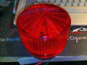
Here’s something anyone in the industrial sector will recognise – it’s a strobe beacon, which continually flashes with power applied to alert operators of a hazard. These older ones are Xenon tube based, instead of LED, so contain a bit more circuitry & some high voltages.

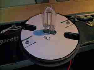
Unhooking the lens reveals the Xenon lamp itself, a horseshoe format tube. A high DC potential is applied across the electrodes of the tube, below the ionisation voltage of the Xenon gas inside. When a flash is called for, a very high voltage – several kV – is applied to a 3rd trigger electrode, applied to the outside of the glass. The high electric field generated is sufficient to ionise enough gas to initiate the main discharge between the electrodes. Since the lamp is across a large capacitor, a massive current flows, generating a high-intensity flash.

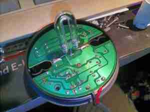
Removing the pair of screws which secure the insulator & PCB reveals the board itself, which is of cheap single-sided construction. There’s no isolation on this circuit, between the internal HV side & DC input.

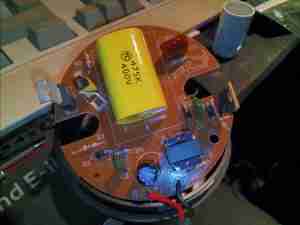
Flipping the board shows all the components. The largest part here is the main flash capacitor in the middle, a plastic film type, 4.7µF 400v. This will be charged to around 350v before the tube is triggered. Charging of the capacitor is done by the transformer at bottom right, switched by the transistor next to it. There are no ICs in this unit to control any timing of the DC-DC converter, so this is probably based around a blocking oscillator. A smaller capacitor to the top right of the main flash cap is part of the trigger circuit, which is charged through a resistor from the main HV supply. When the voltage on this capacitor reaches a high enough level, the large SCR on the left side of the board switches on, dumping the charge on that capacitor through the trigger transformer, the small yellow device with the white wire. This small transformer generates the high voltage pulse to trigger the flash lamp.
