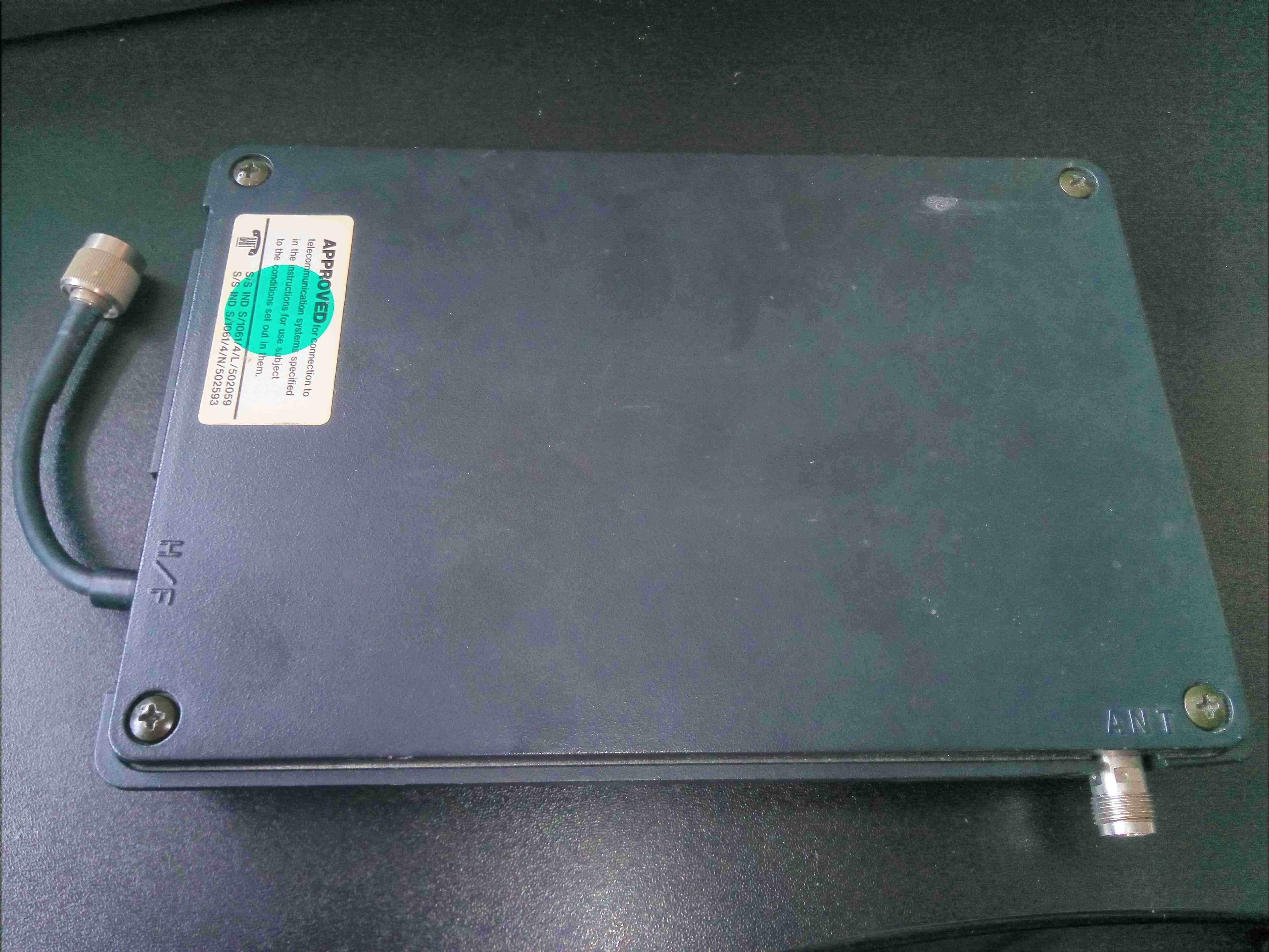
Here’s a blast from the past, before the time of GSM networks. This is a power amplifier from an Analogue mobile phone, on the ETACS system. This unit will output, according to the TACS standard, about 10W of RF power in the 900MHz band. RF connections on this unit are made via TNC connections, and a DIN connector for power & control. This unit is made of solid aluminium, no plastic casing here! The metal is needed for both RF shielding, and heatsinking capability for the power amplifier module inside.
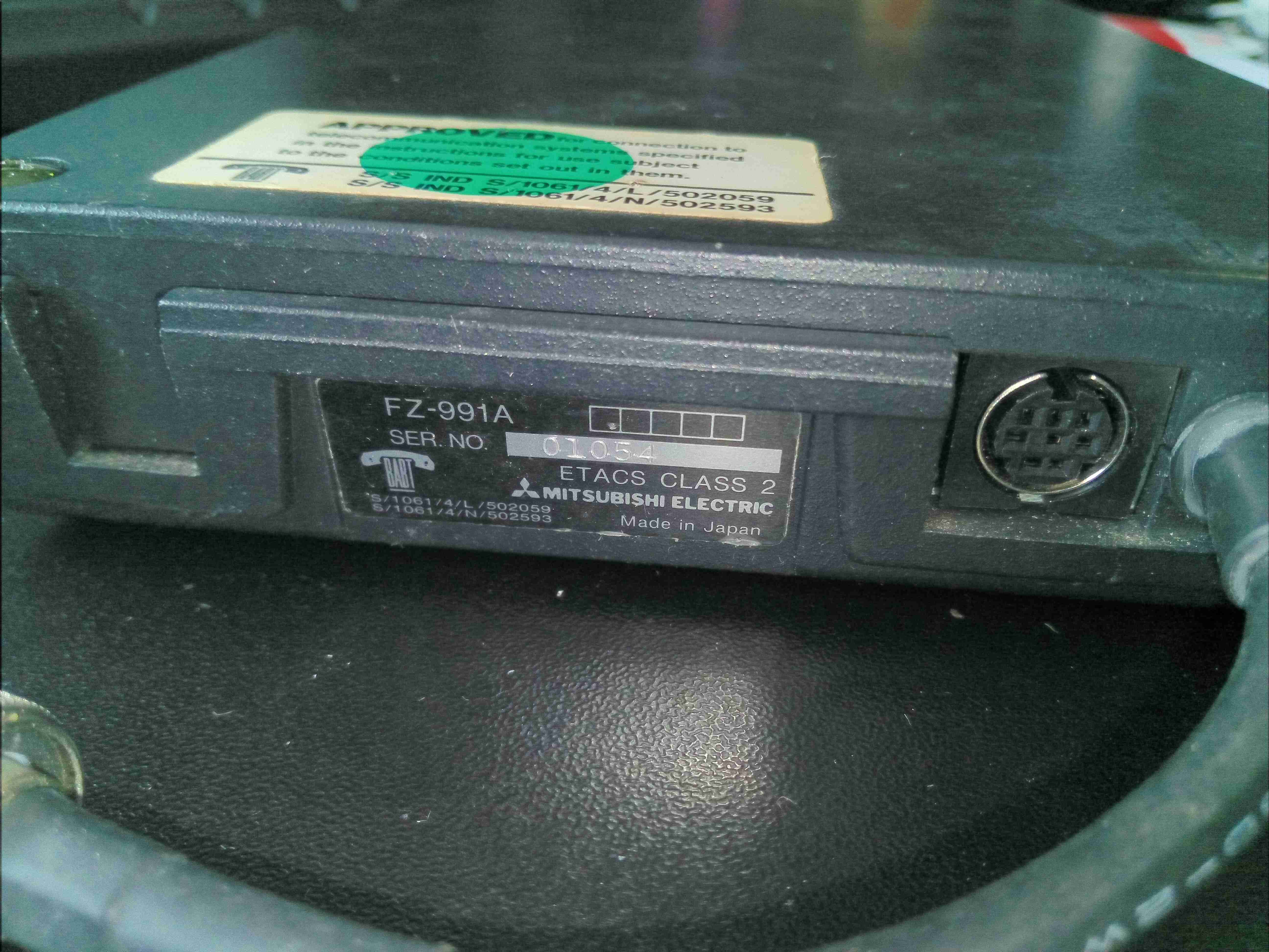
Here’s the rating label, and the control connector.
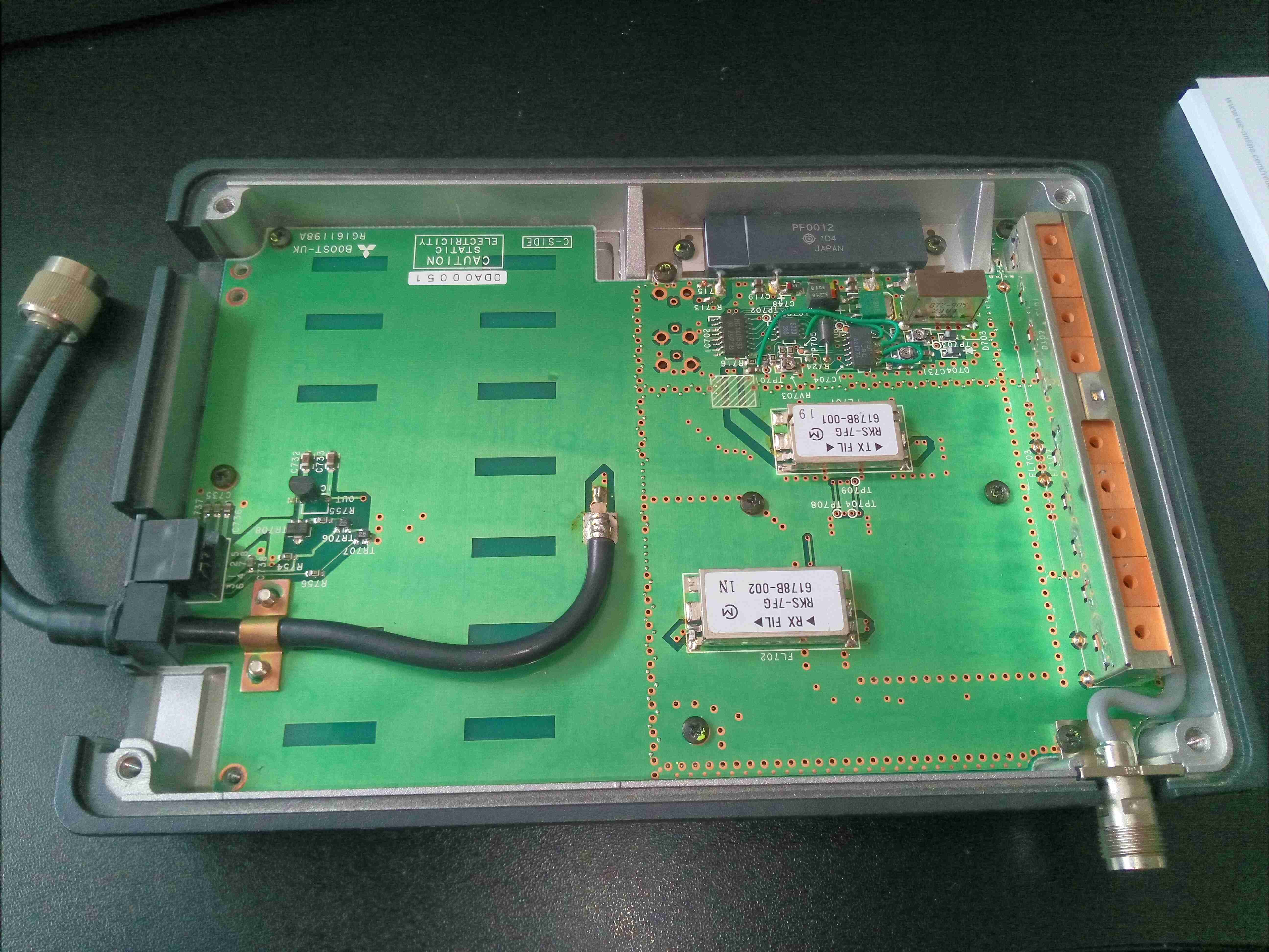
Removing 4 screws allows the lid to be removed from the cast base. There’s RF shielding gasket around the edge of the lid, along with the internal sections of the amplifier. The board is pretty sparsely populated. RF input is via the short cable on the left, and output to the antenna on the lower right.
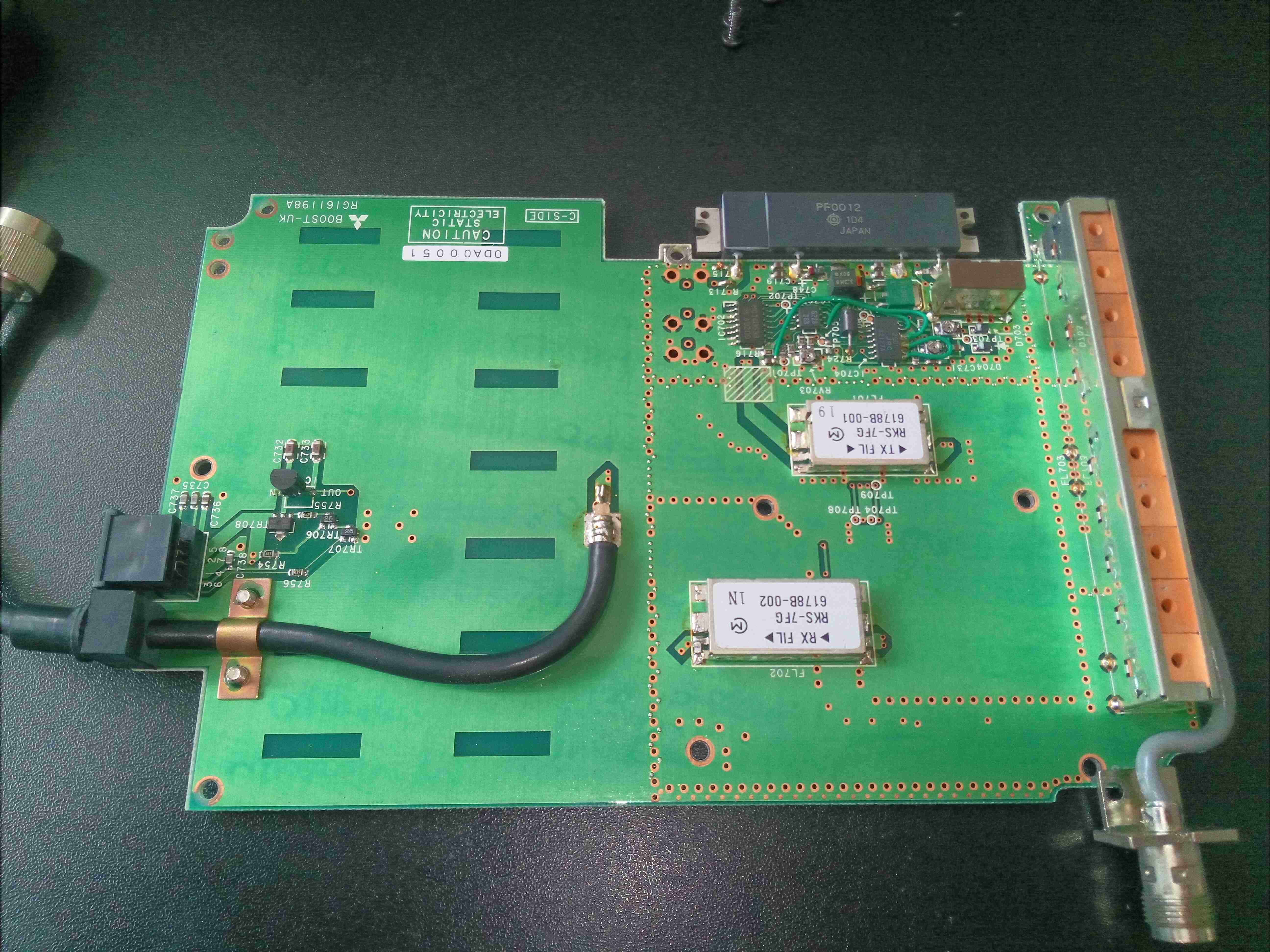
A few more screws & the PCB comes out of the cast base.
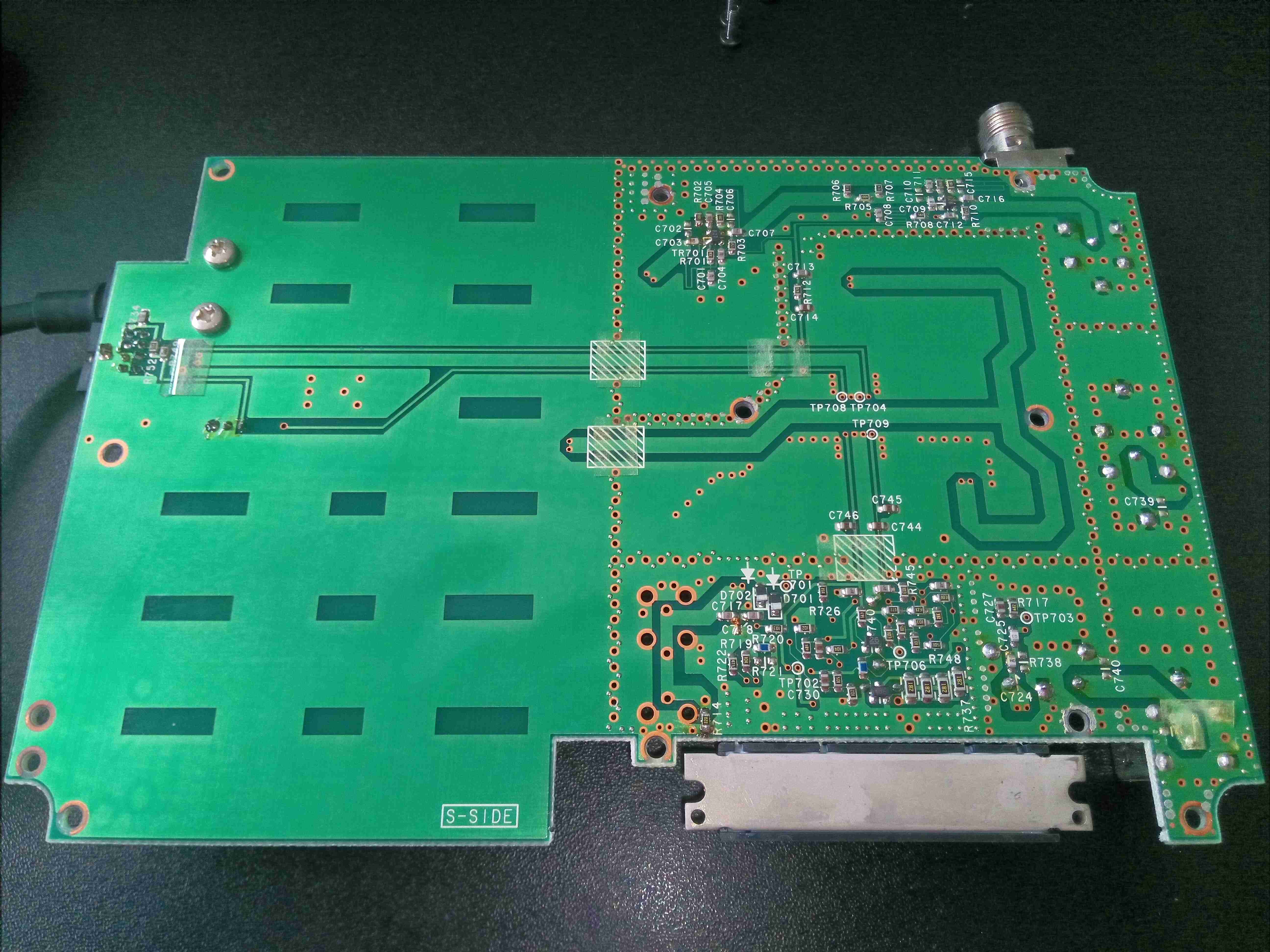
Not much on the bottom of the board, apart from a lot of via stitching & passive components.
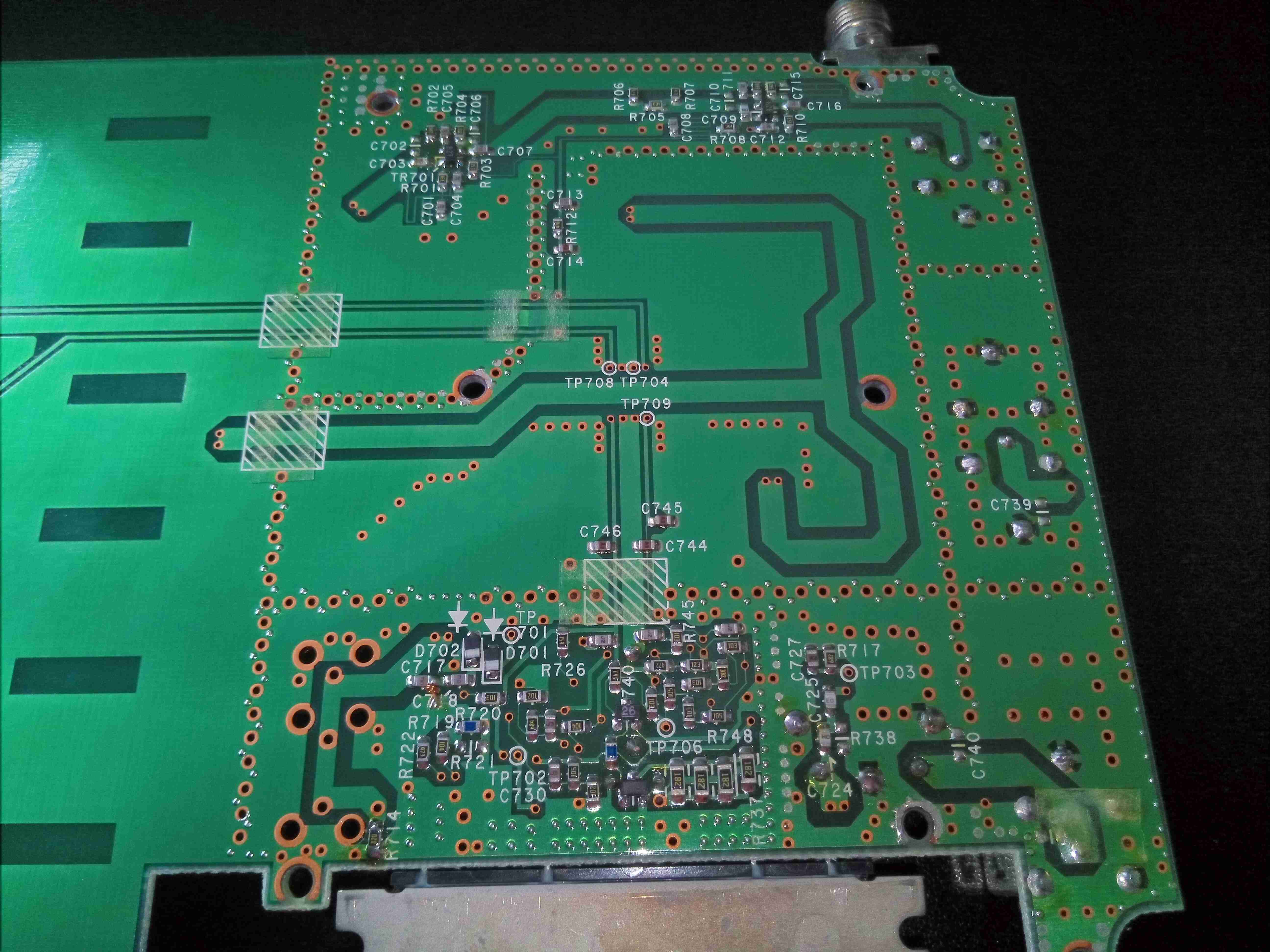
Under the RF section is very dense with passives, and via stitching to separate the sections.
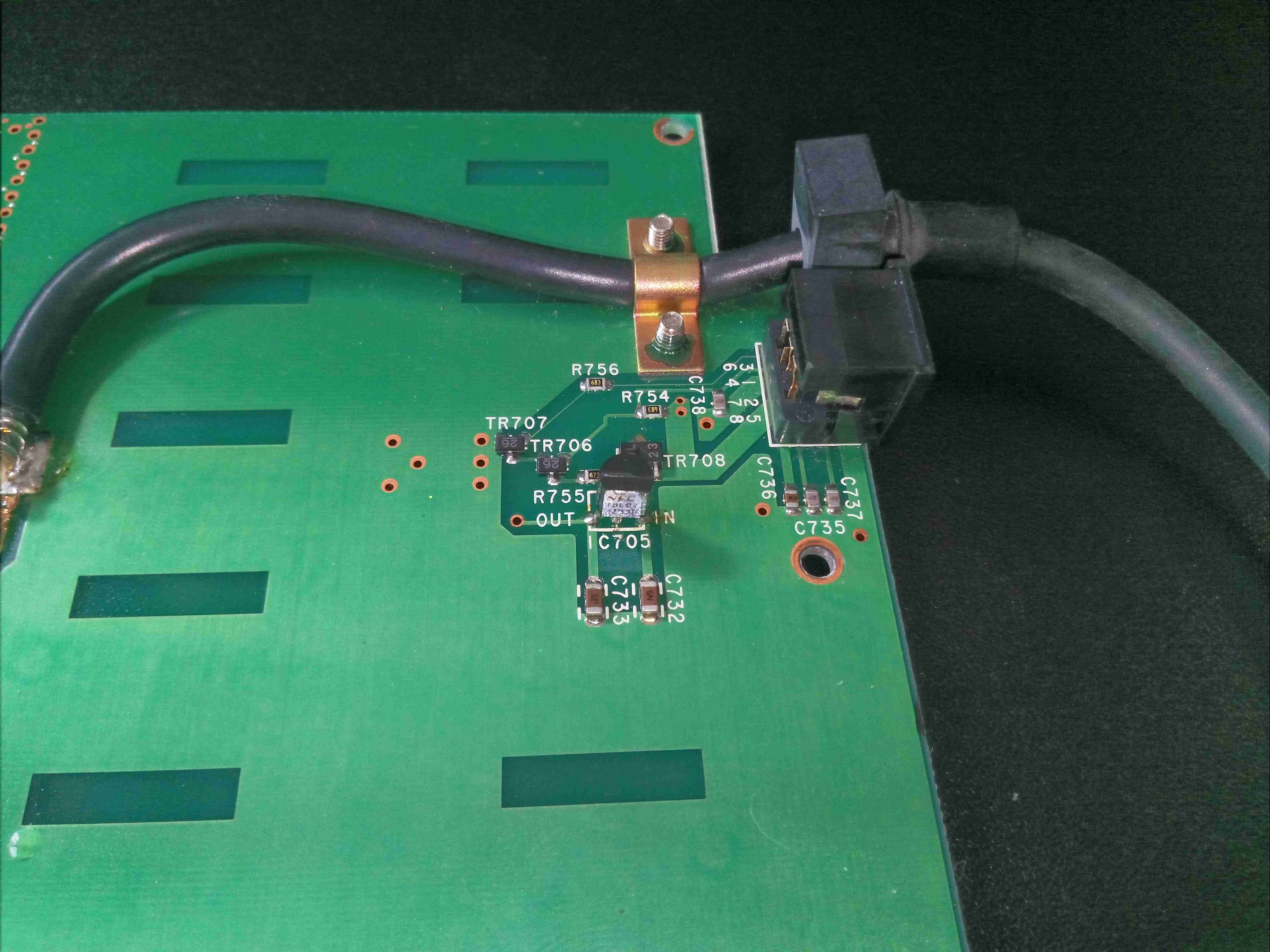
There’s a 7v linear regulator near the power input connection, most likely to provide a biasing supply for the RF power section.
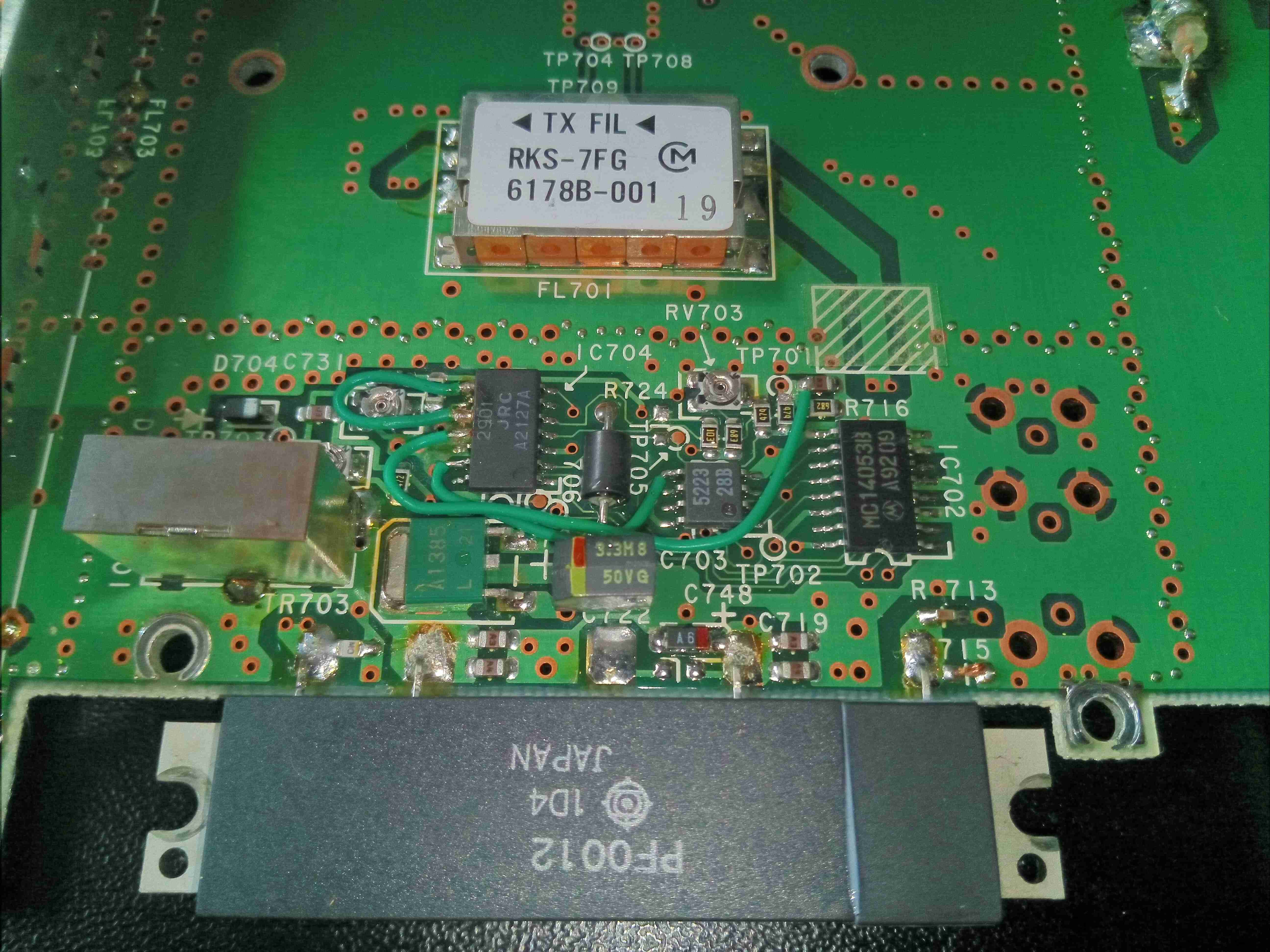
The main power amplifier is a Hitachi PF0012 module, these were very common in radios, and contain all the components required for an RF PA stage. I couldn’t find a specific datasheet for this module unfortunately. There are some support components inclusing a NMJ2901 Quad comparator from JRC, and a MC14051B Analogue Mux/Demux.
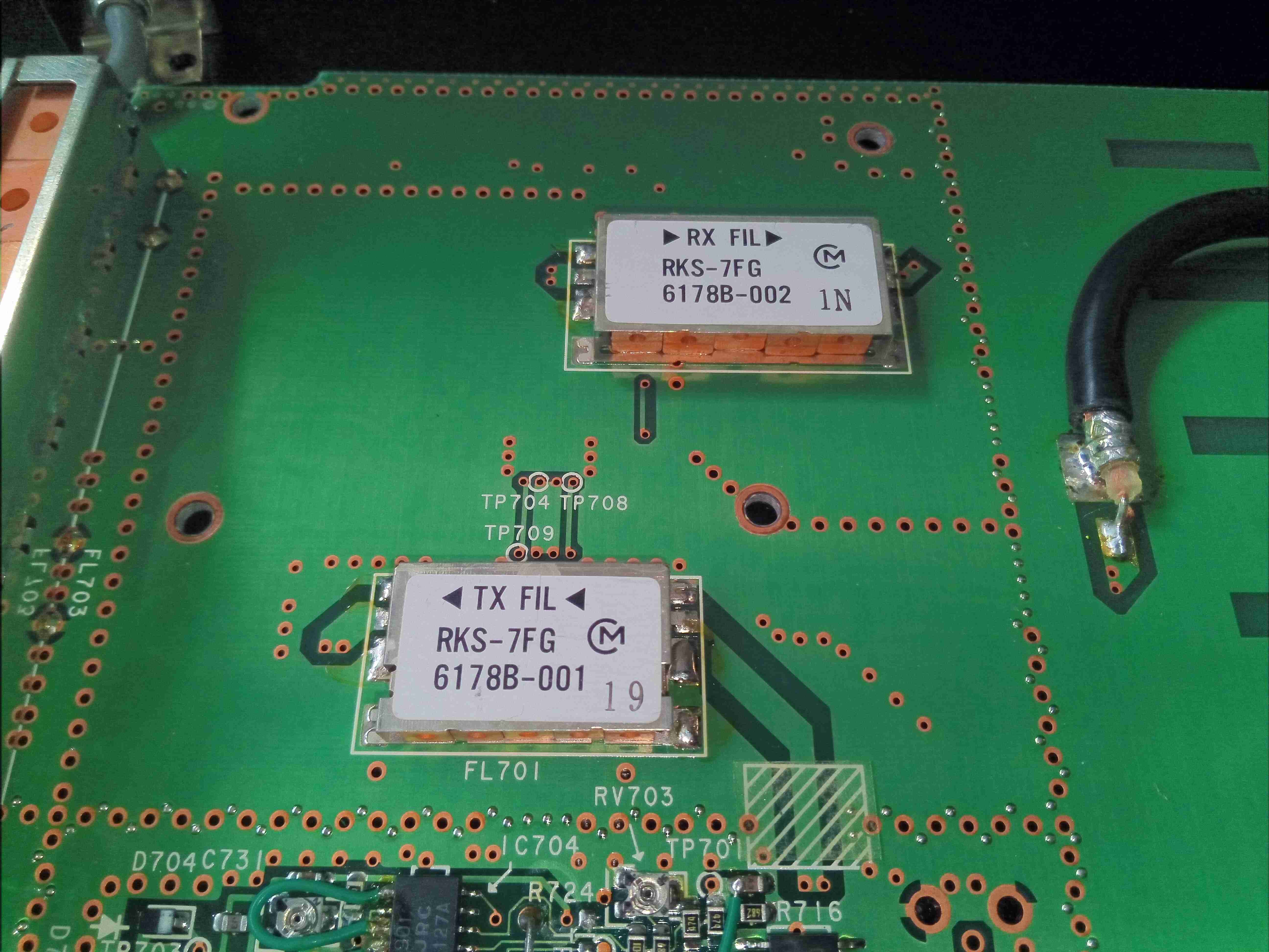
Filtering of the TX & RX frequencies is done by this pair of units from MuRata
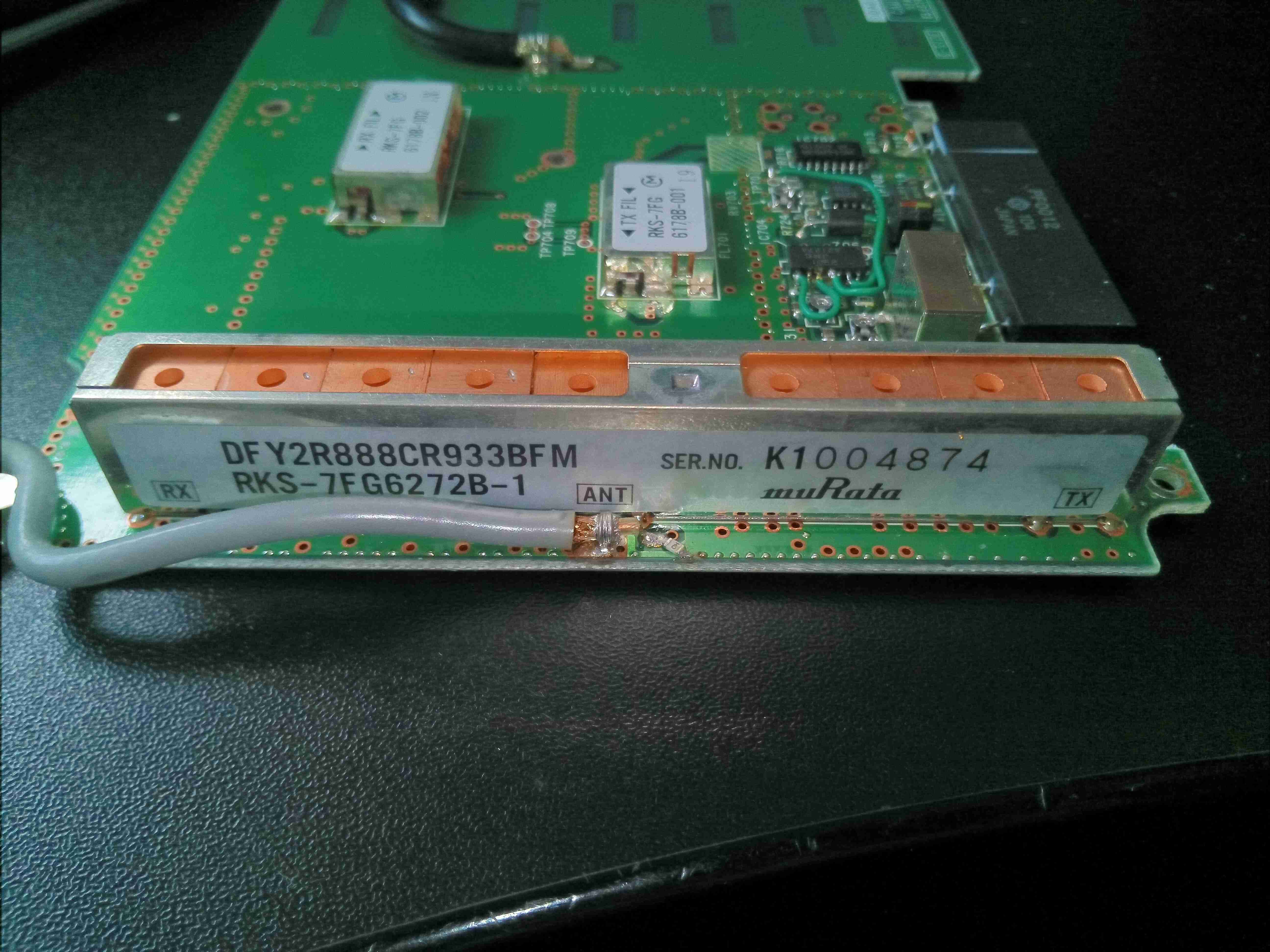
Finally, there’s an antenna duplexer on the output side, also from MuRata. Unfortunately no datasheets available for any of these parts.
