There’s a common problem with all Software Defined Radios – their input stage is wide open, and therefore susceptible to desensitisation by local high power transmitters. The main culprits are broadcasts in the FM band, from 88-108MHz. Commercial stopband filters are available to solve this issue, by cutting out the FM Broadcast band. Before I ordered a commercially produced filter, I figured I’d try my hand at building my own.
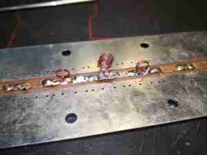
Here’s the filter I came up with, a Type 2 Chebyshev. It’s built on a prototype stripline PCB, with SMA connectors at either end for I/O. This was created with the help of a filter calculator, the response of the filter can be seen below:
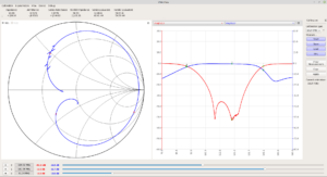
The response of the filter isn’t bad at all! It’s shifted up a little high on the scale, with the lower -3dB point being at 91MHz rather than 88MHz, but it does indeed chop out the broadcast band by -52dB. The high -3dB point is at 141MHz.
Let’s look at a commercial filter now, here’s the unit below, it’s definitely been size & cost optimized!
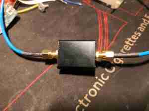
The box is tiny, not much bigger than the SMA connectors!
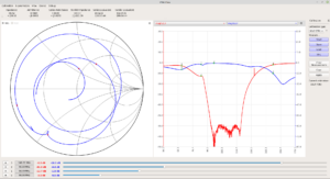
Looking at the plot from the NanoVNA, it’s clear this is also a Type 2 Chebyshev, but it’s more effective. This has a stopping power of -82dB, it’s also better centred.
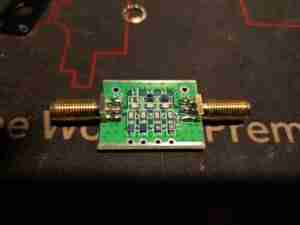
The board easily removes from the external shell. The SMA connectors are edge launch, which is good for maintaining impedance. There are a couple more stages of filtering in here than I put on my filter, which explains the much improved blocking characteristics. There does appear to be some damage though – there’s an inductor missing from the left side of the PCB. This is probably responsible for the odd response at the low end. There clearly was an inductor there, as the solder fillets are still present. Maybe this was removed at the factory as a form of tuning?
