Recently I found the need to do some measurements on 75Ω CATV equipment, only having 50Ω test equipment to use. For this, matching networks exist to convert 50Ω to 75Ω, but they’re fairly simple, so building them was a viable option.
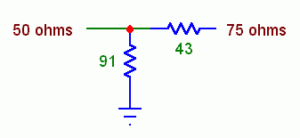
Above is the very simple schematic to create the 75Ω match. To help keep any parasitics down, this circuit will be built directly onto the back of BNC connectors, that are soldered back-to-back, before being covered in shielding tape.
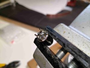
Here’s the first 50Ω BNC connector, with the resistor network soldered on. I’ve used 4x 360Ω resistors in parallel to create the 90Ω to ground, and a single 43Ω series resistor on the centre pin.
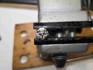
This end view of the arrangement shows the 4 resistors evenly spaced around the centre pin & soldered to the shell.
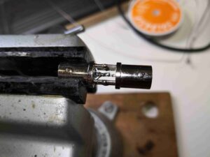
The centre pin of the 75Ω BNC connector is trimmed down to match the length needed to touch the end of the series resistor, and it’s soldered in place. It’s a bit tricky, soldering within the gap between 2 of the ground pins!
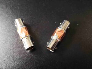
Finally, the internals are shielded with copper tape, soldered at the seams.
