Posted on Leave a comment

DeWalt Clone 18v Battery Pack Teardown

Clone Battery Pack
Clone Battery Pack
Clone Battery Pack

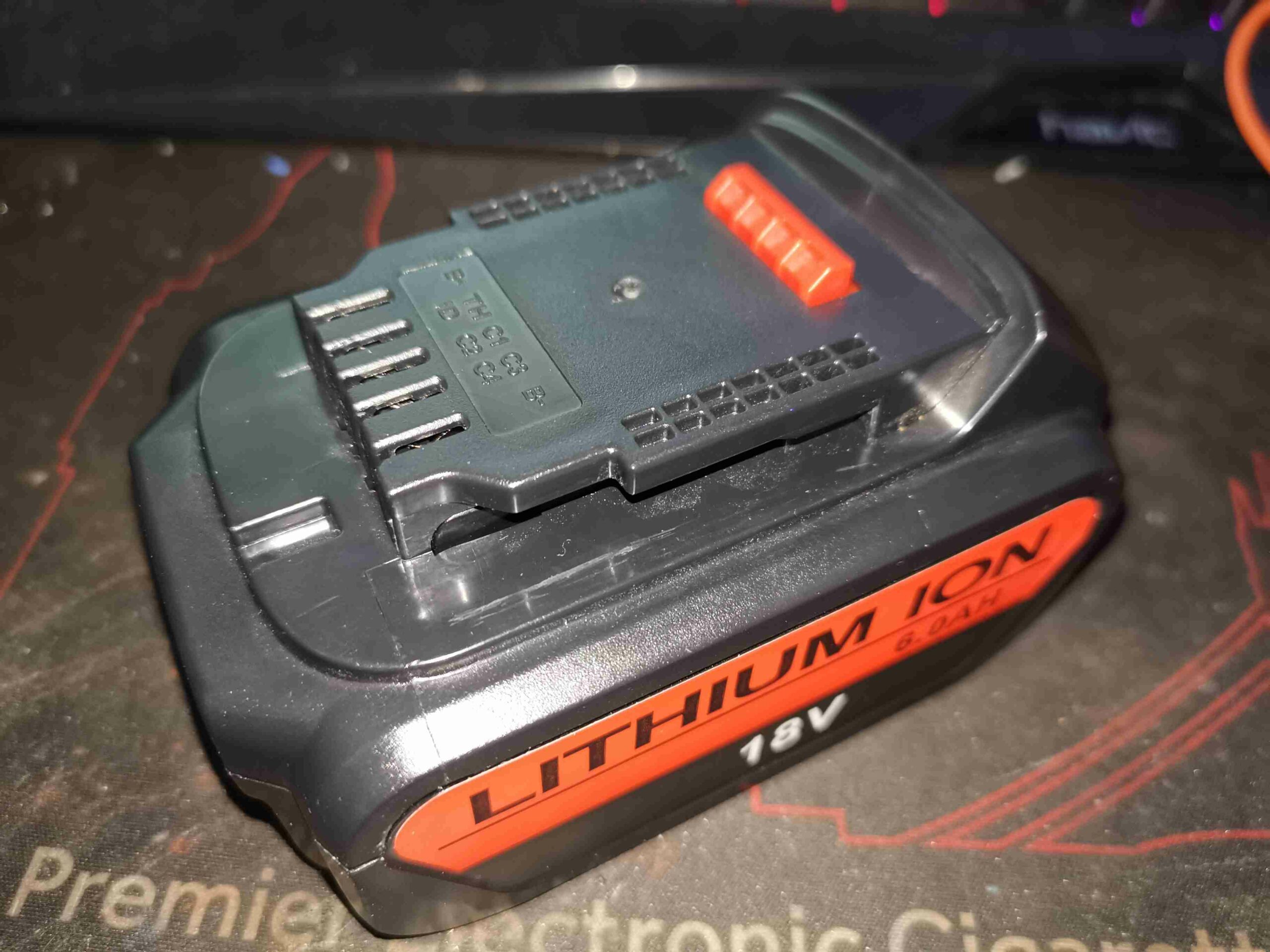
I bought two of these packs for my new DeWalt combi drill, as the branded packs are very expensive and there’s unlikely to be much of a difference in cells used. I was a little mistaken on this, as you’ll see!

Battery Terminals
Battery Terminals

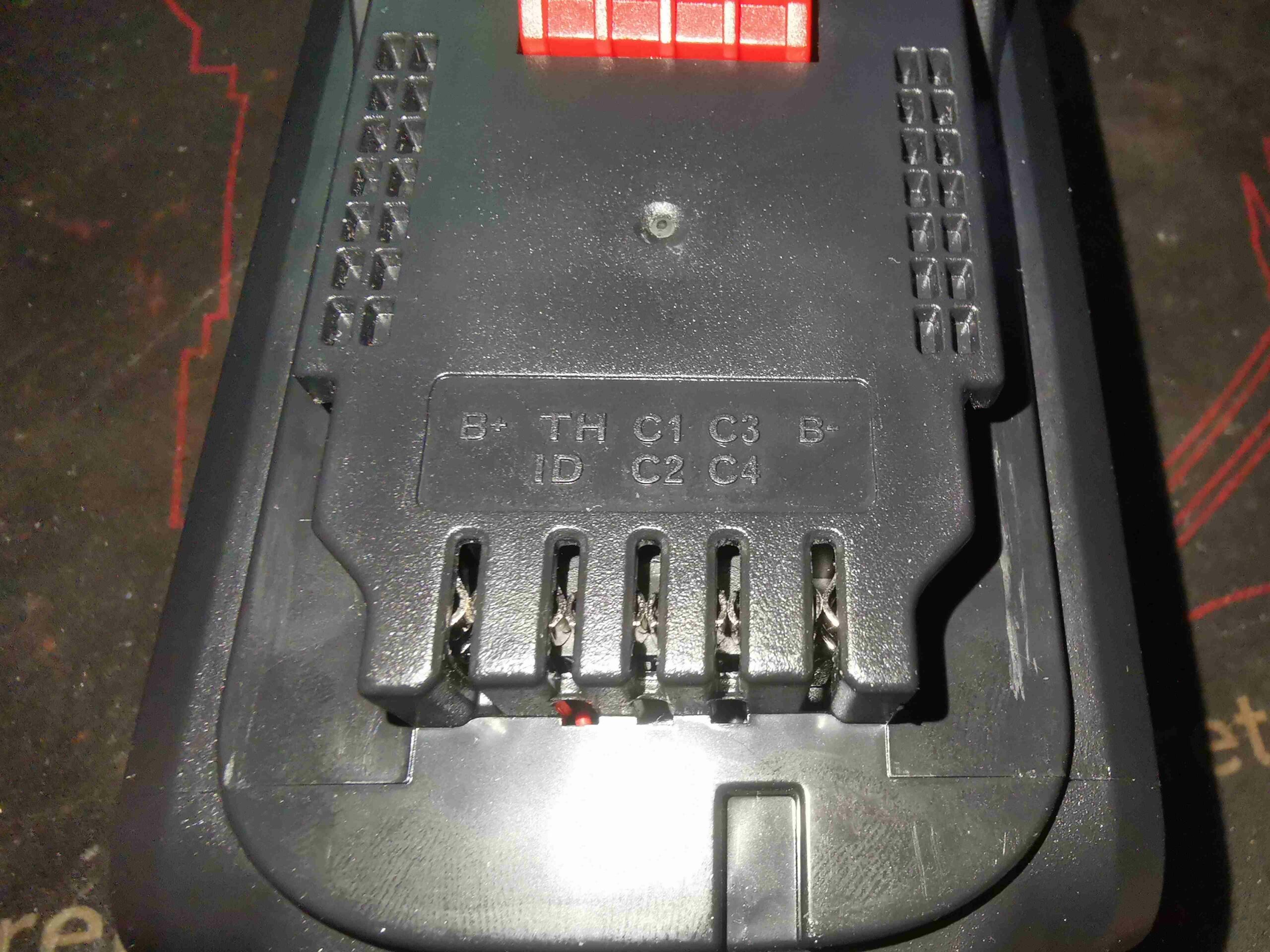
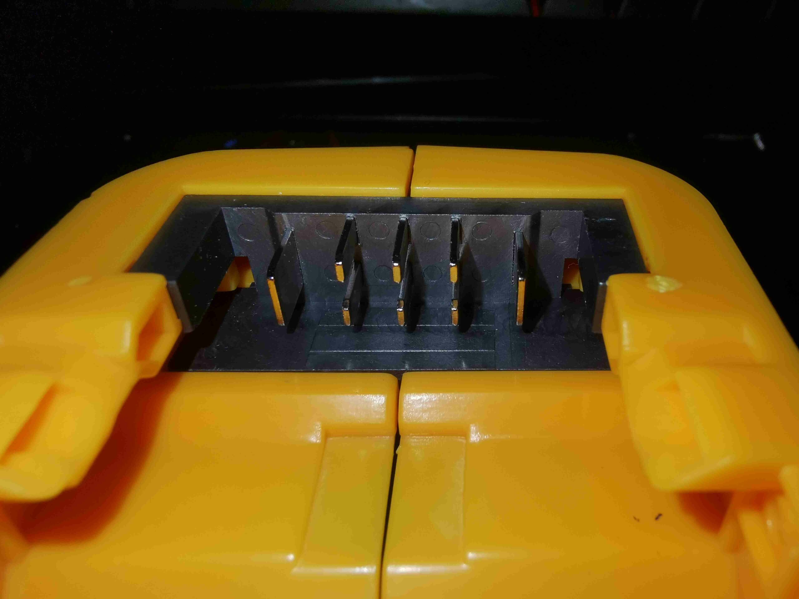
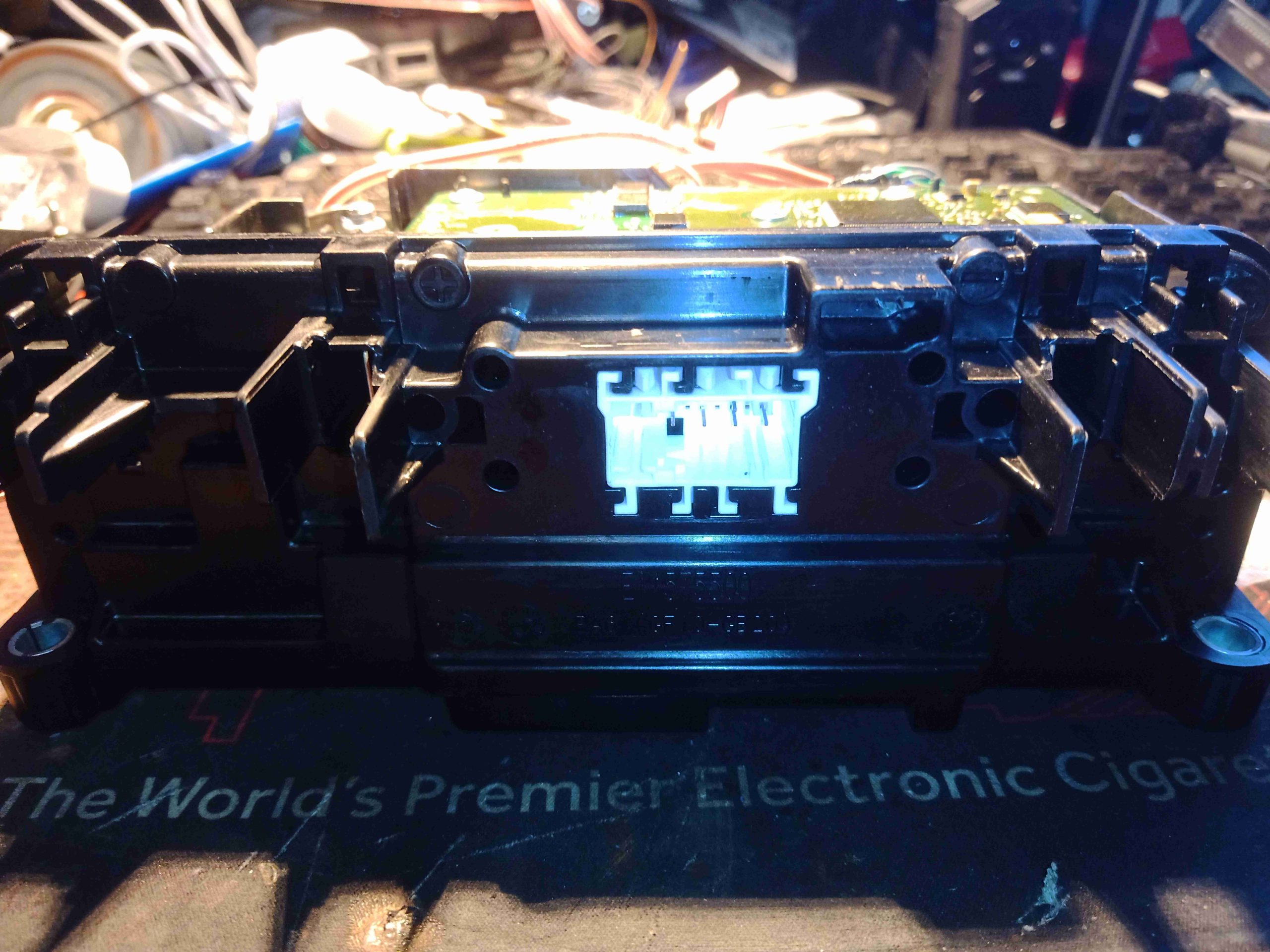
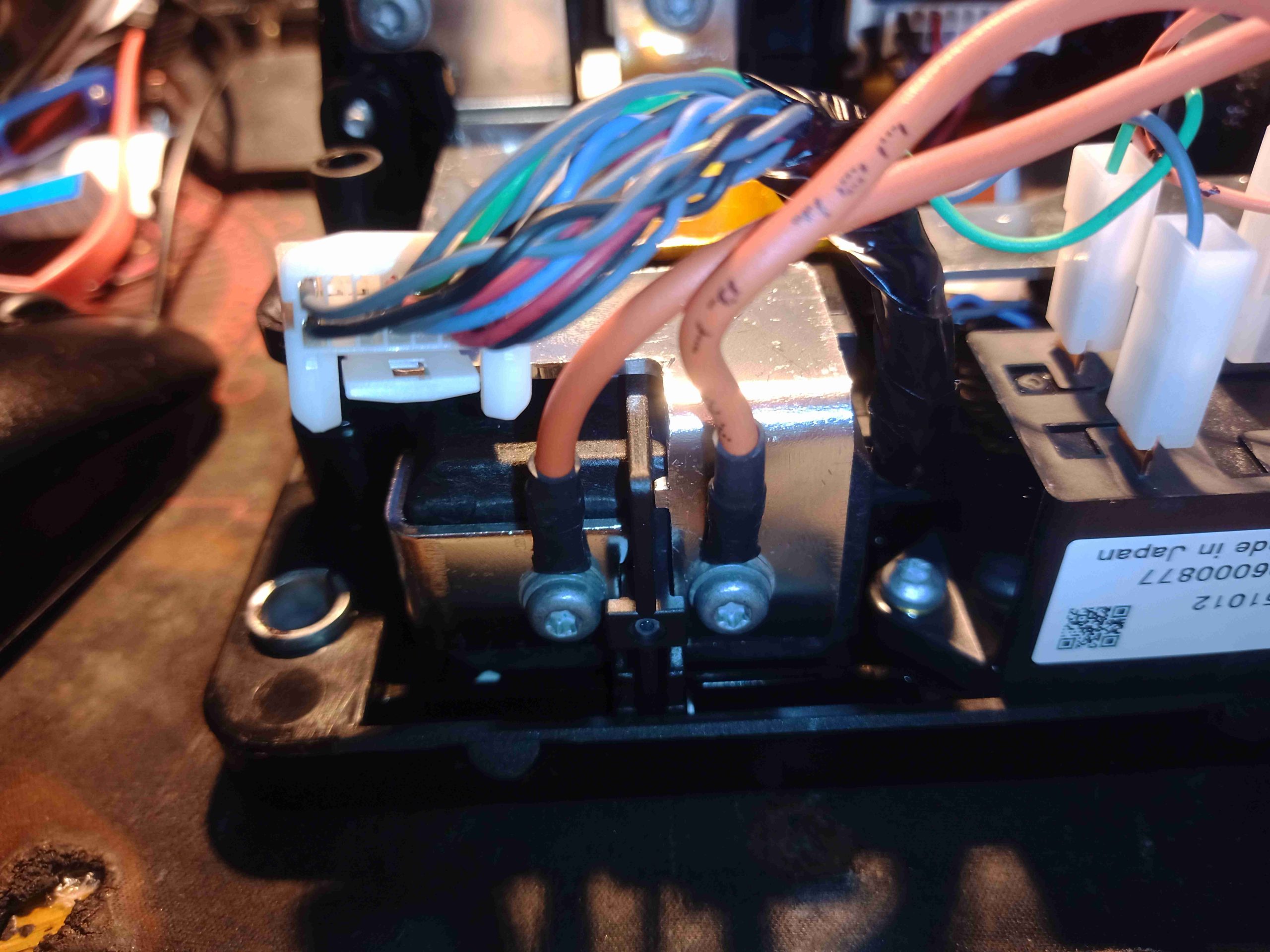
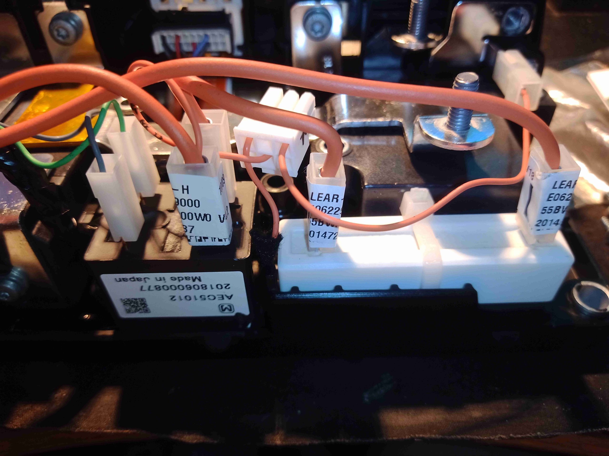
The top of the unit has the battery connections, with all the cell balance lines, along with an ID pin, and a TH pin. The TH pin connects a 10K NTC thermistor up to B+.

Battery Label
Battery Label

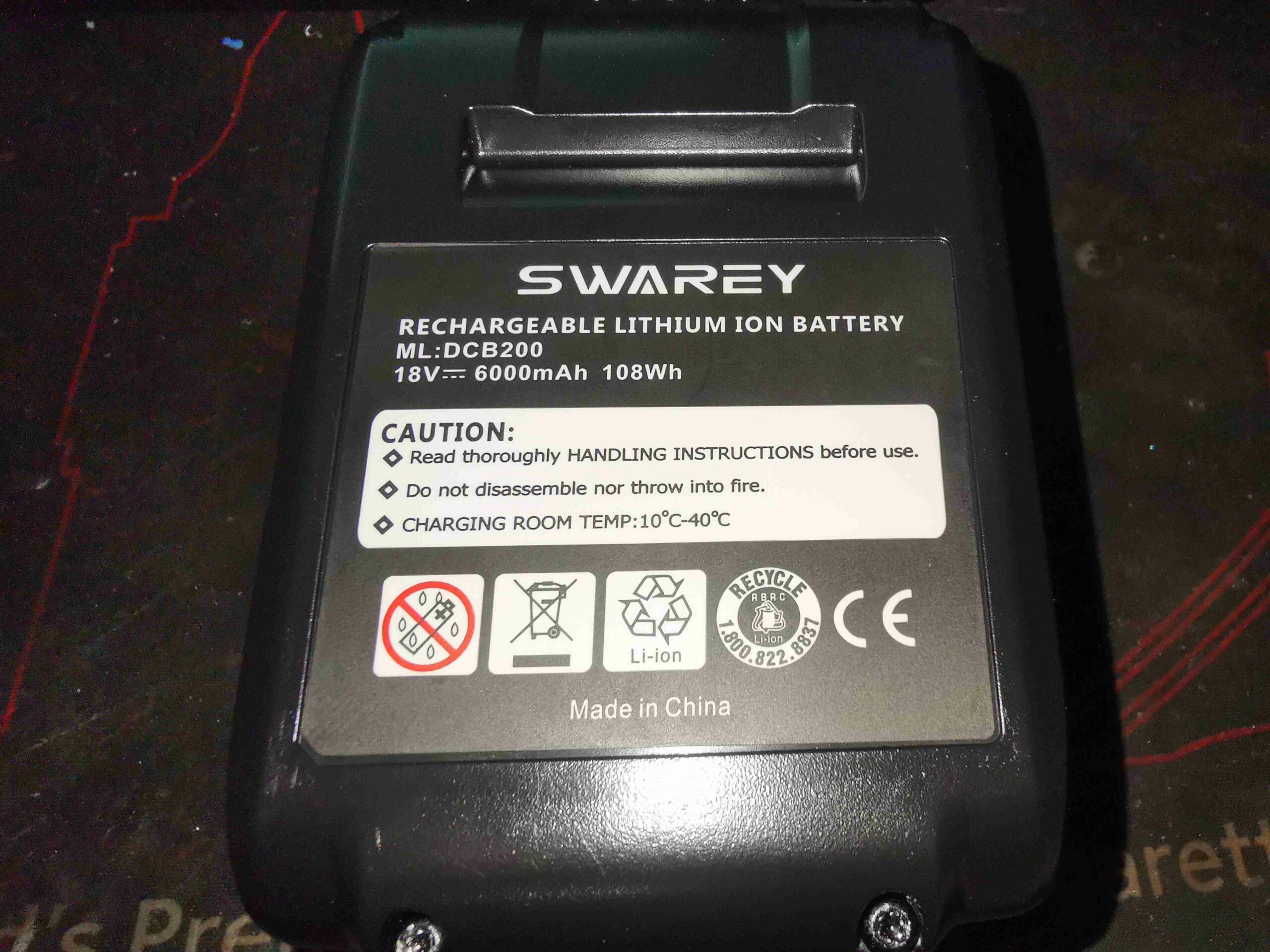
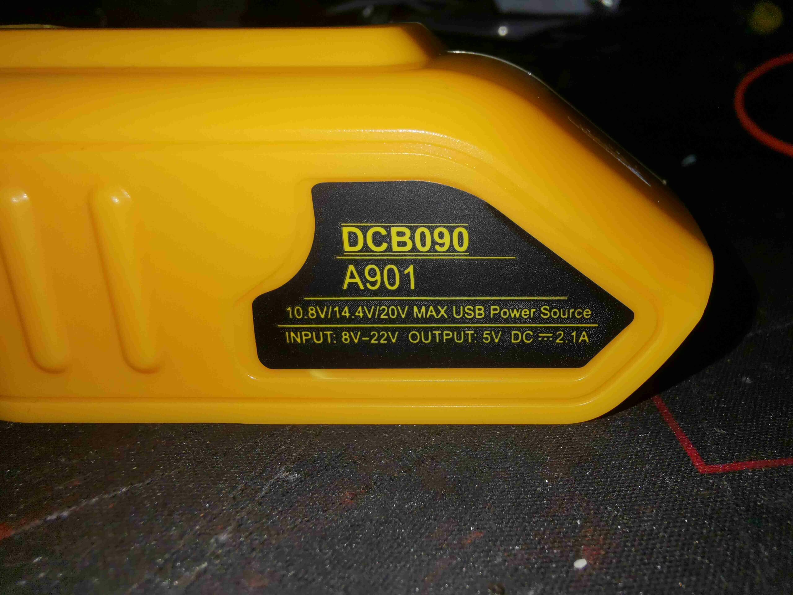
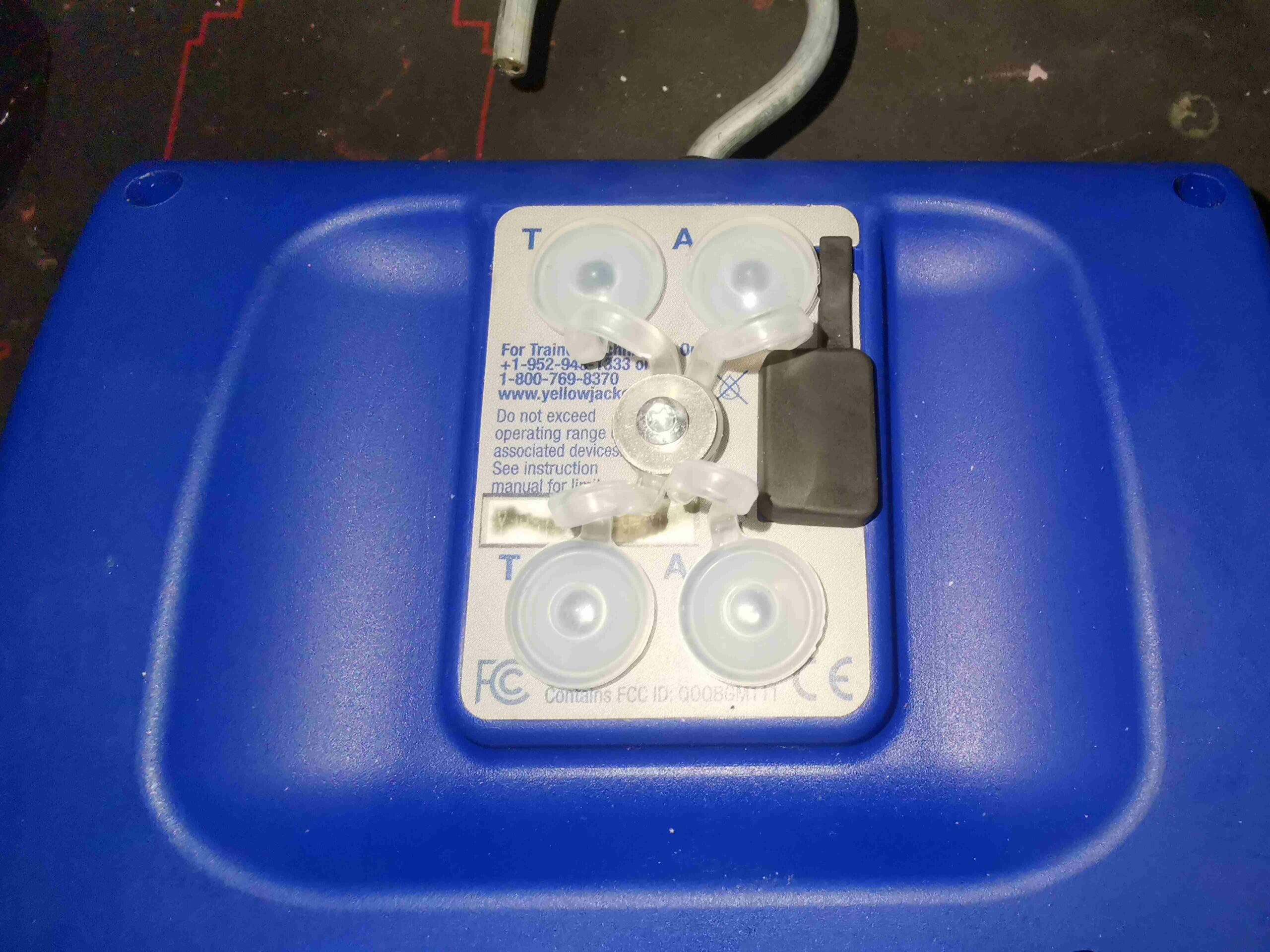
The bottom of the unit has the rating & warning label. This claims to be a 6Ah pack, but it’s nowhere even close!

Top Cover Removed
Top Cover Removed

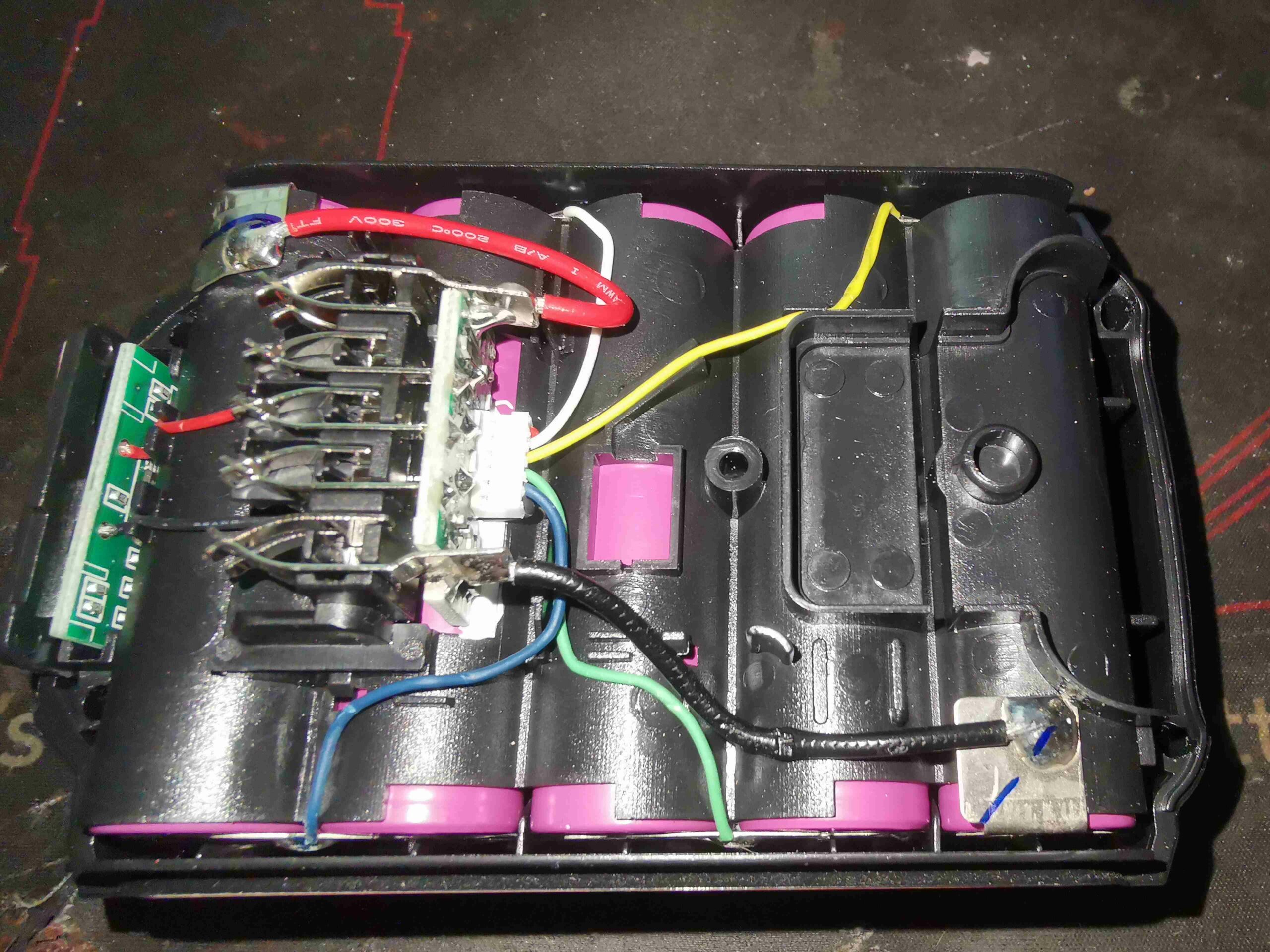
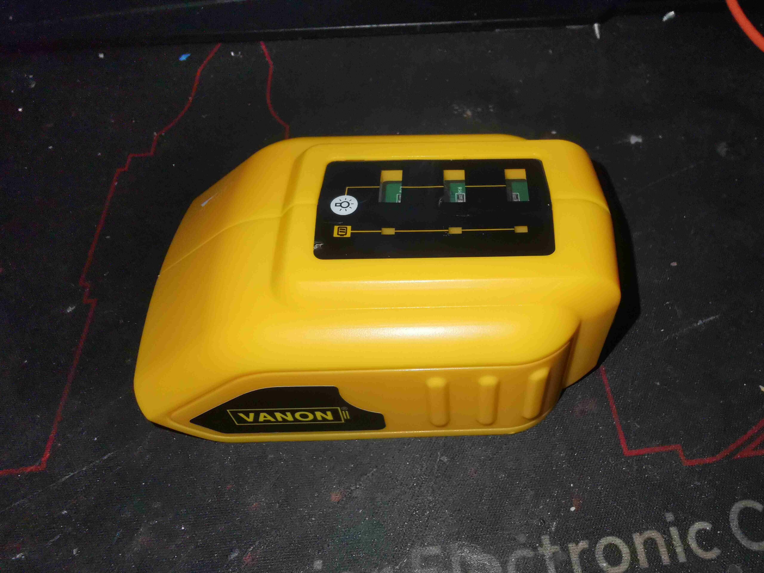
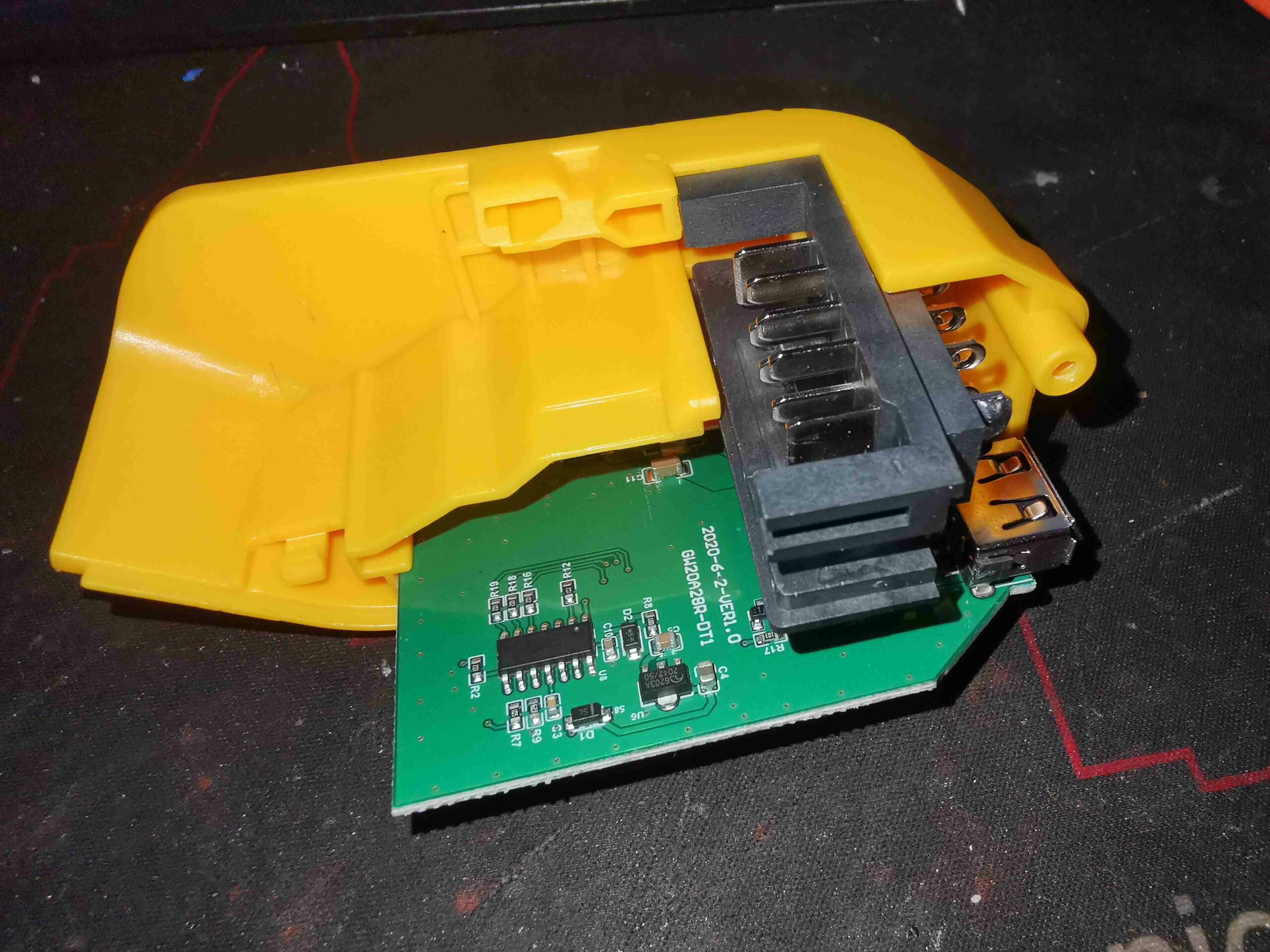
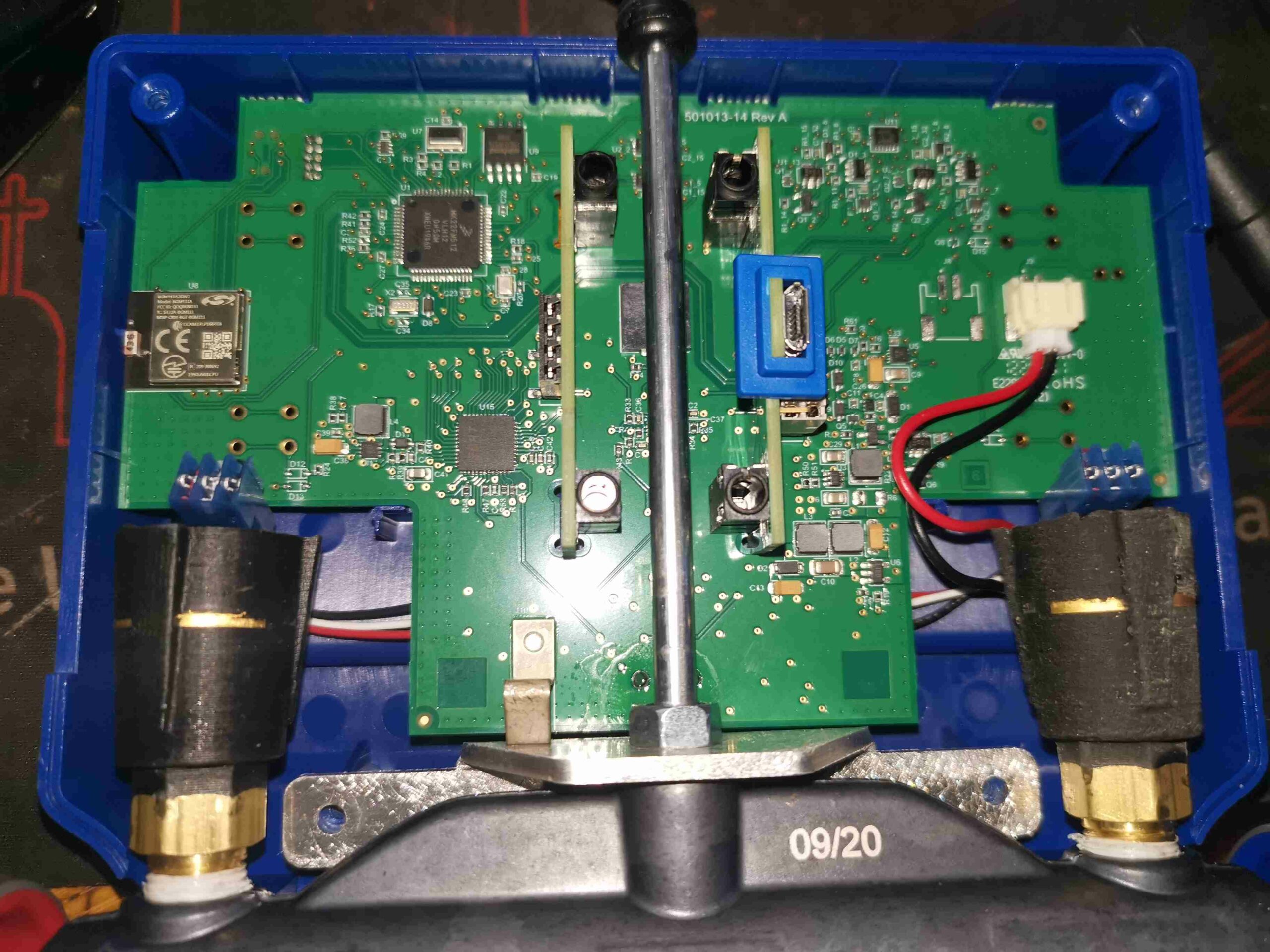
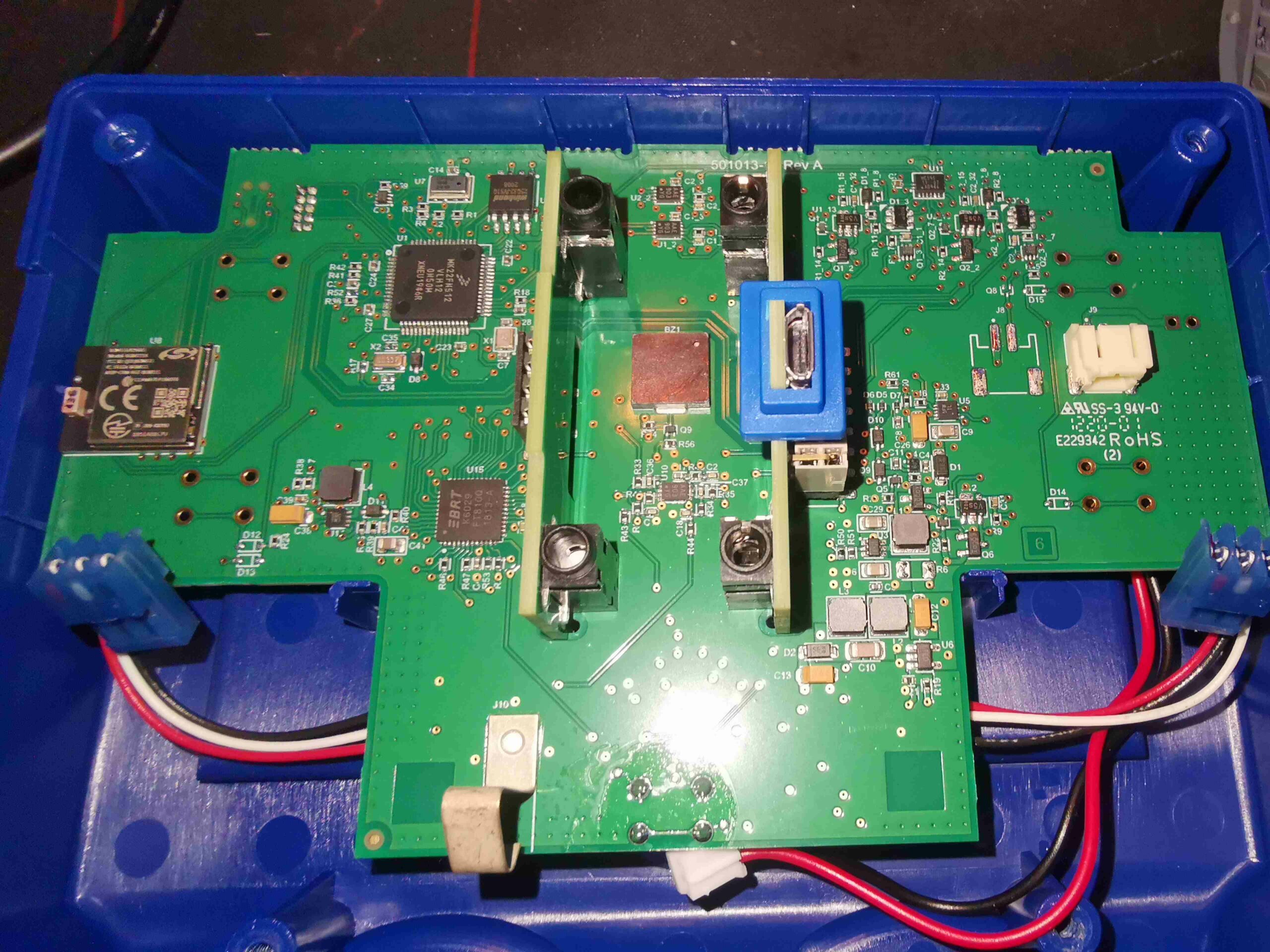
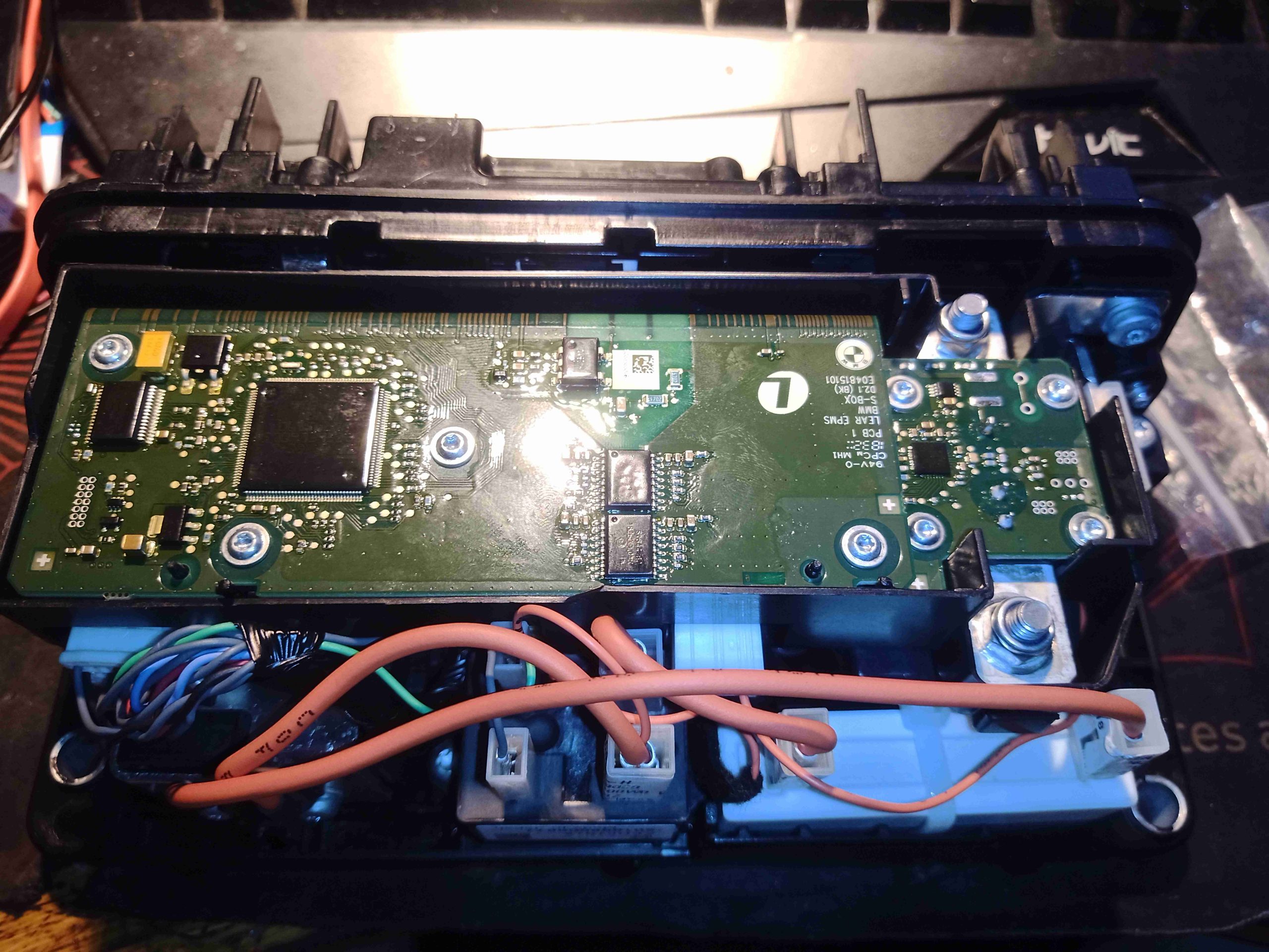
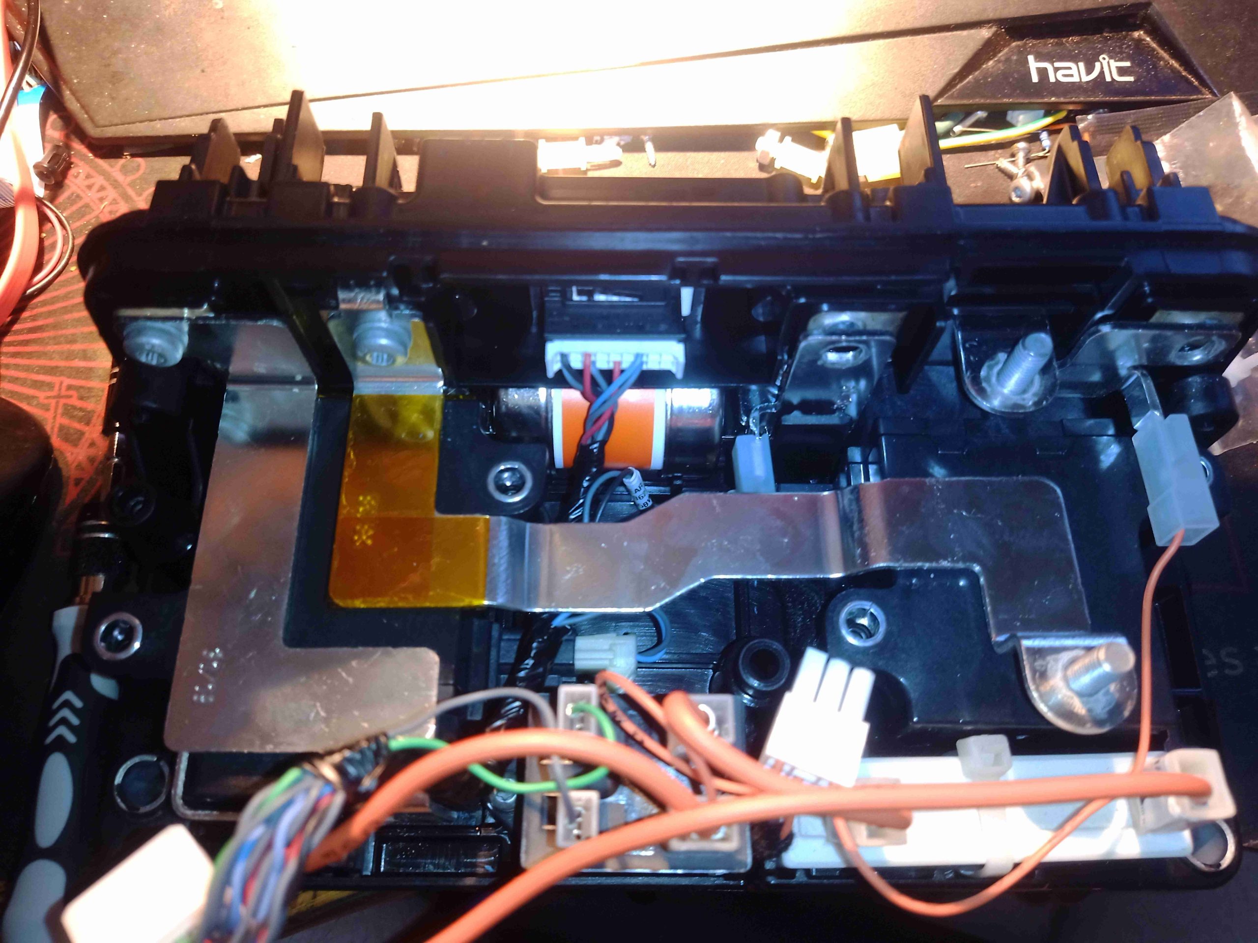
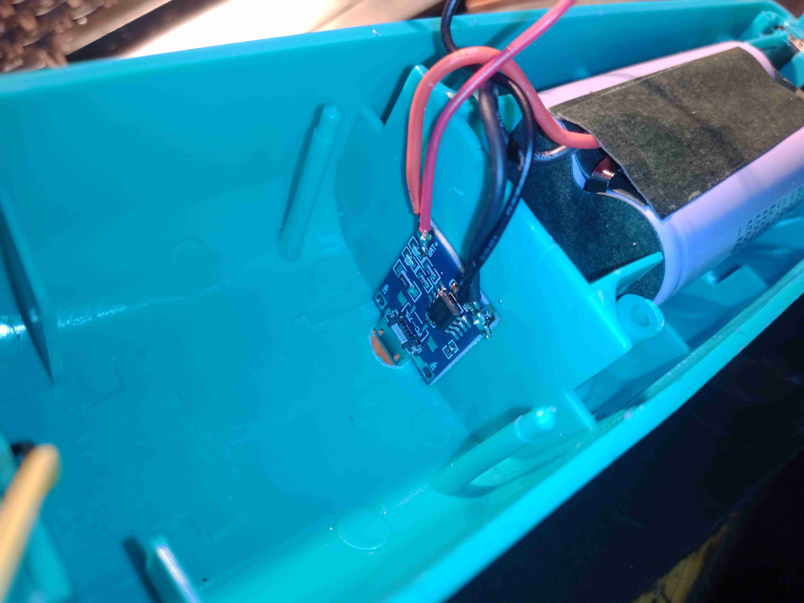
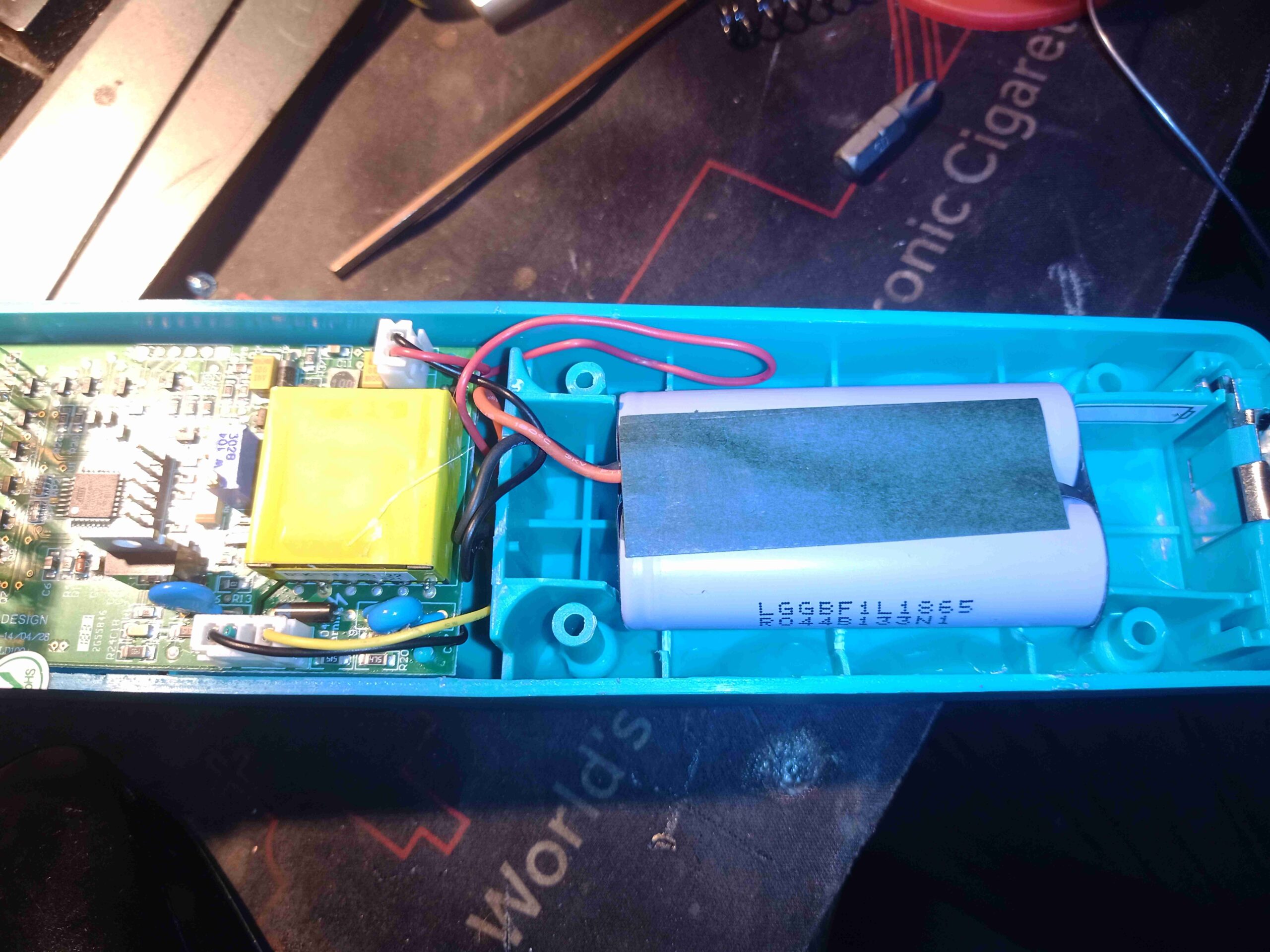
Removing 4 Torx screws gives access to the internals. The cells are all fitted into a plastic holder. There’s a small PCB holding the connector pins, and all the cells connect up to this for the balance outputs. There’s a small PCB on the side of the pack that holds the components for the battery meter.

Connector PCB
Connector PCB

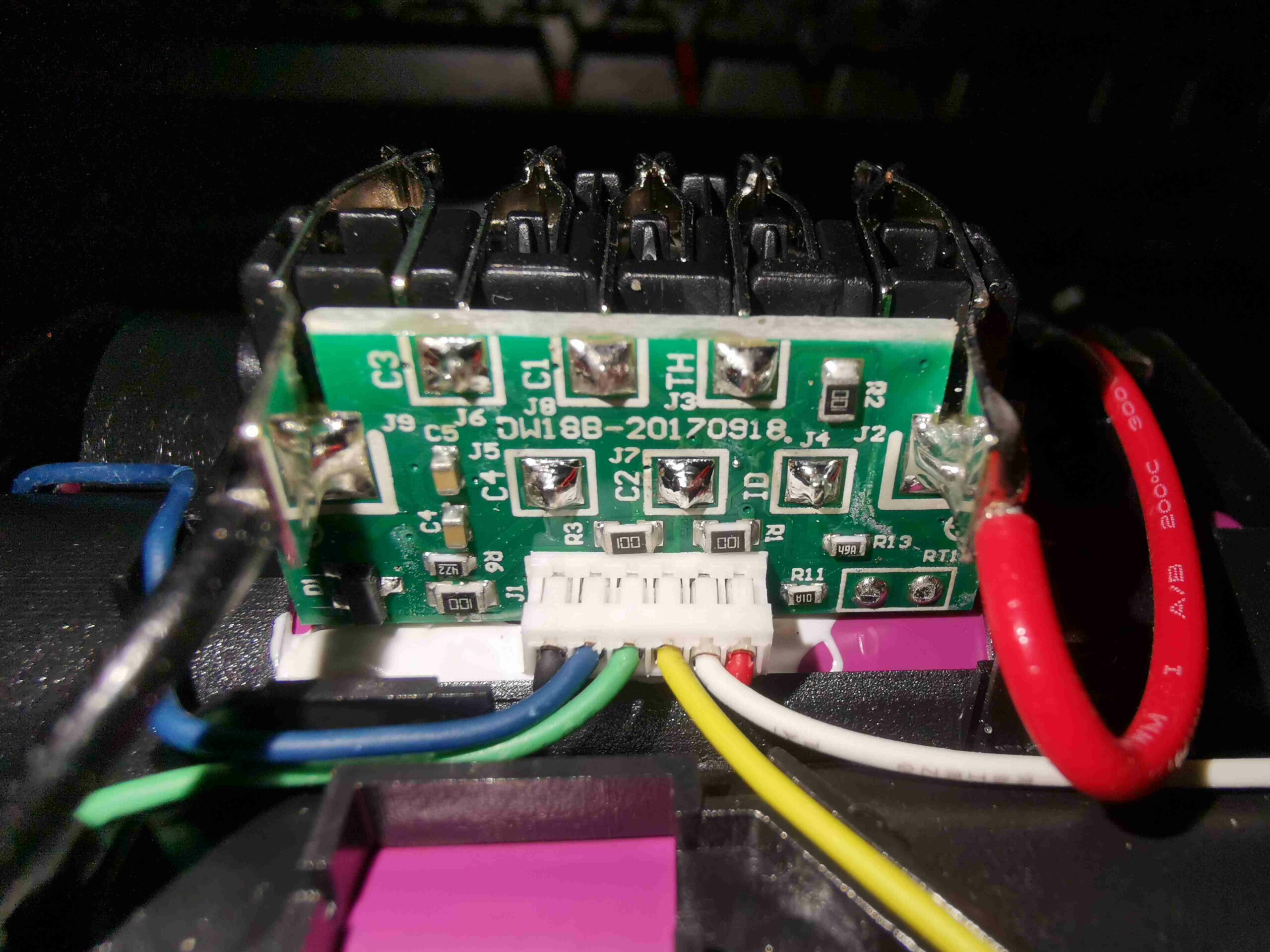
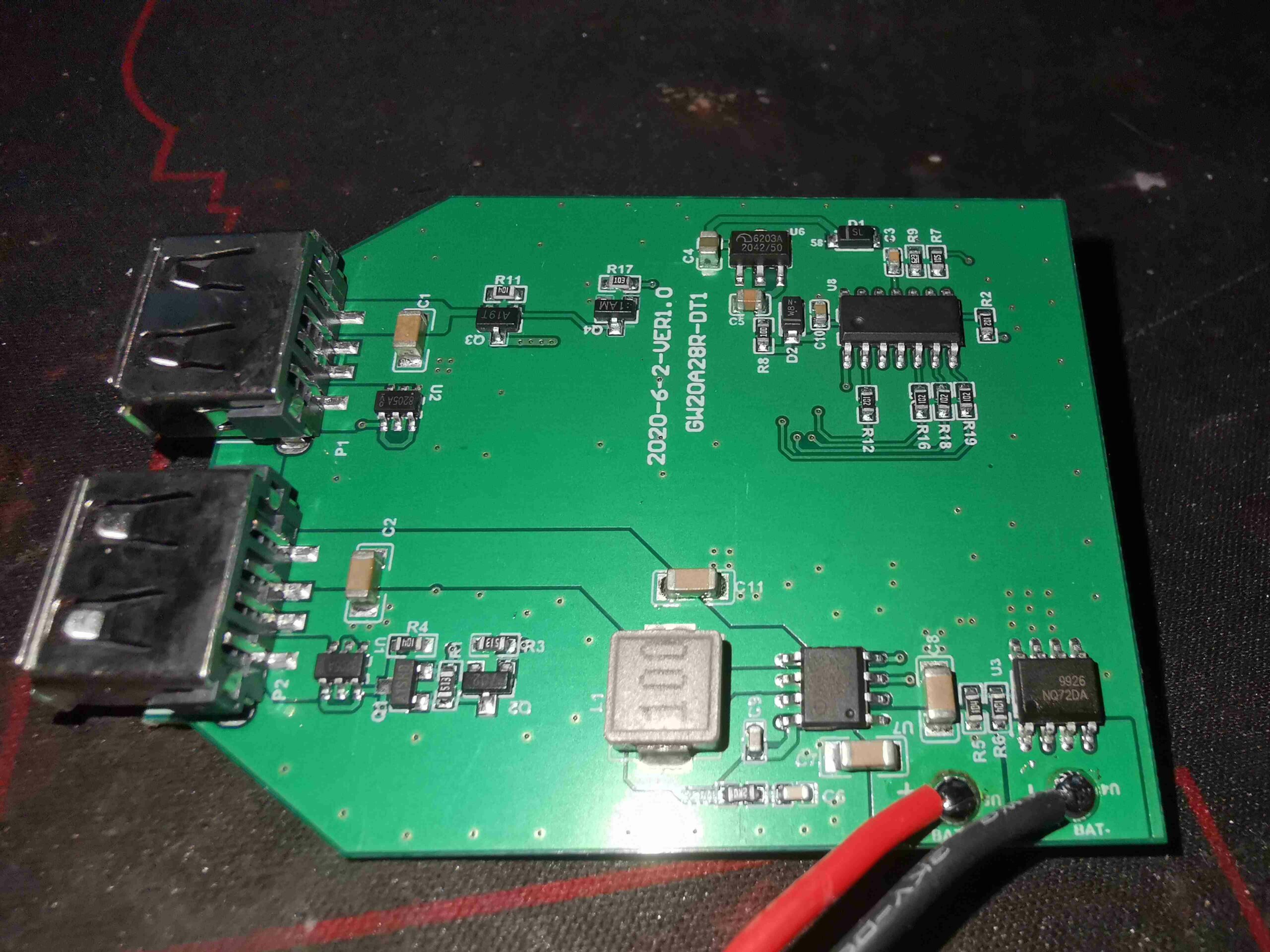
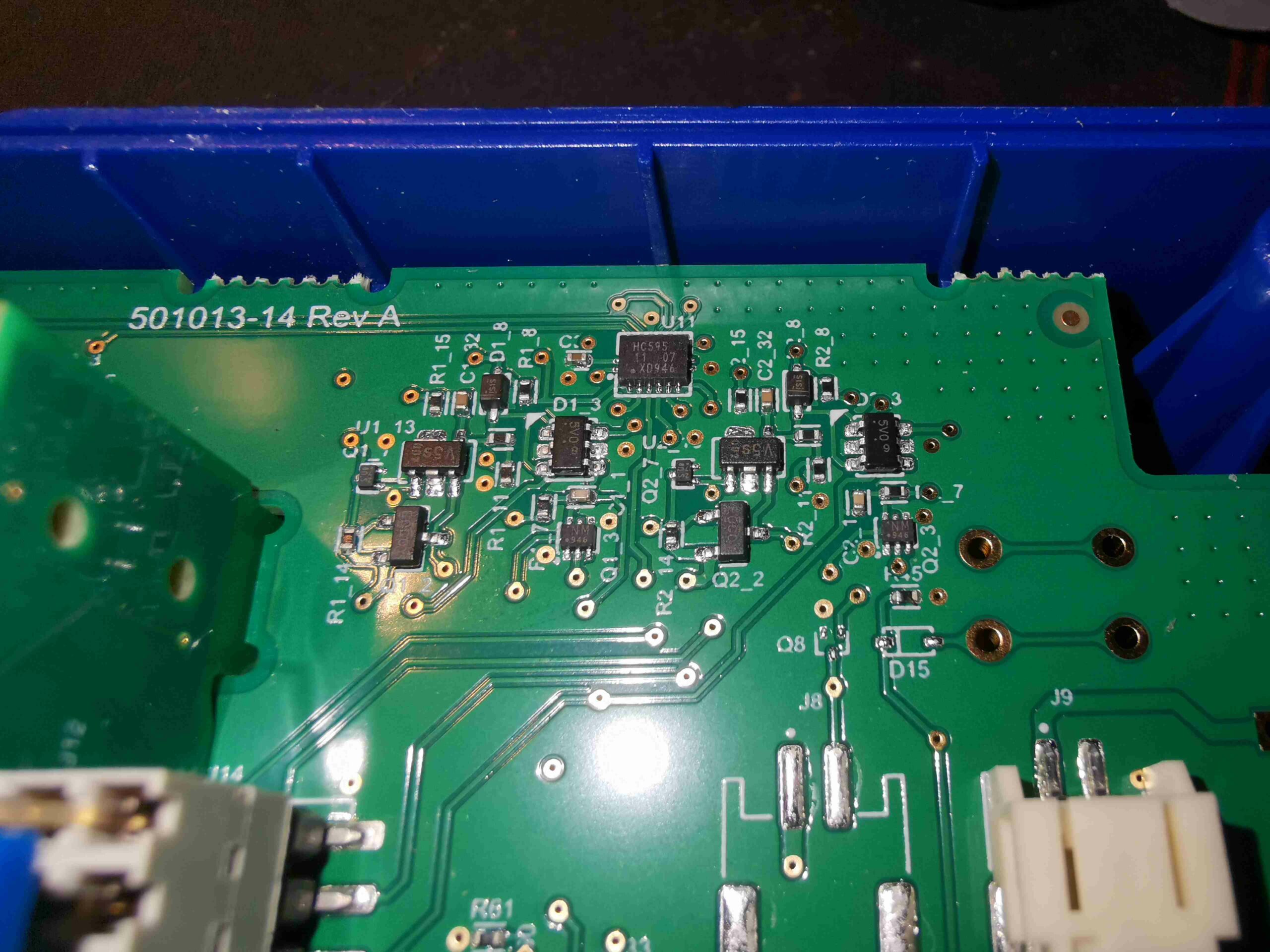
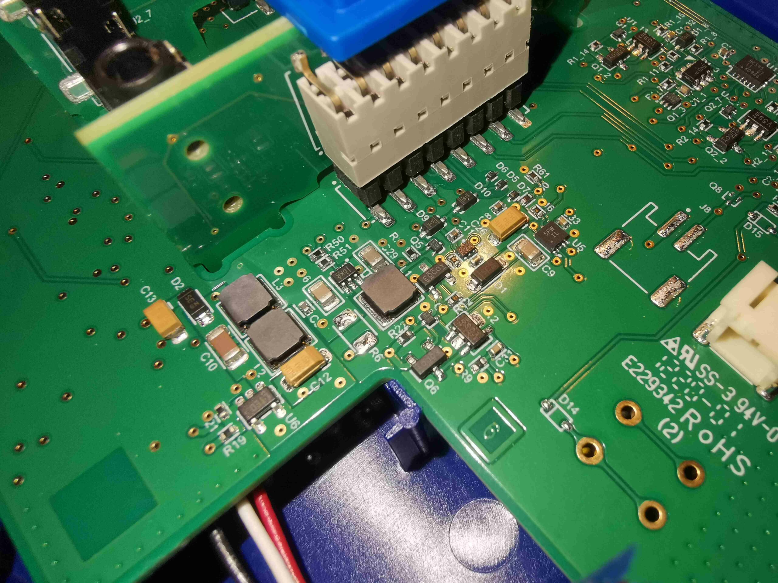
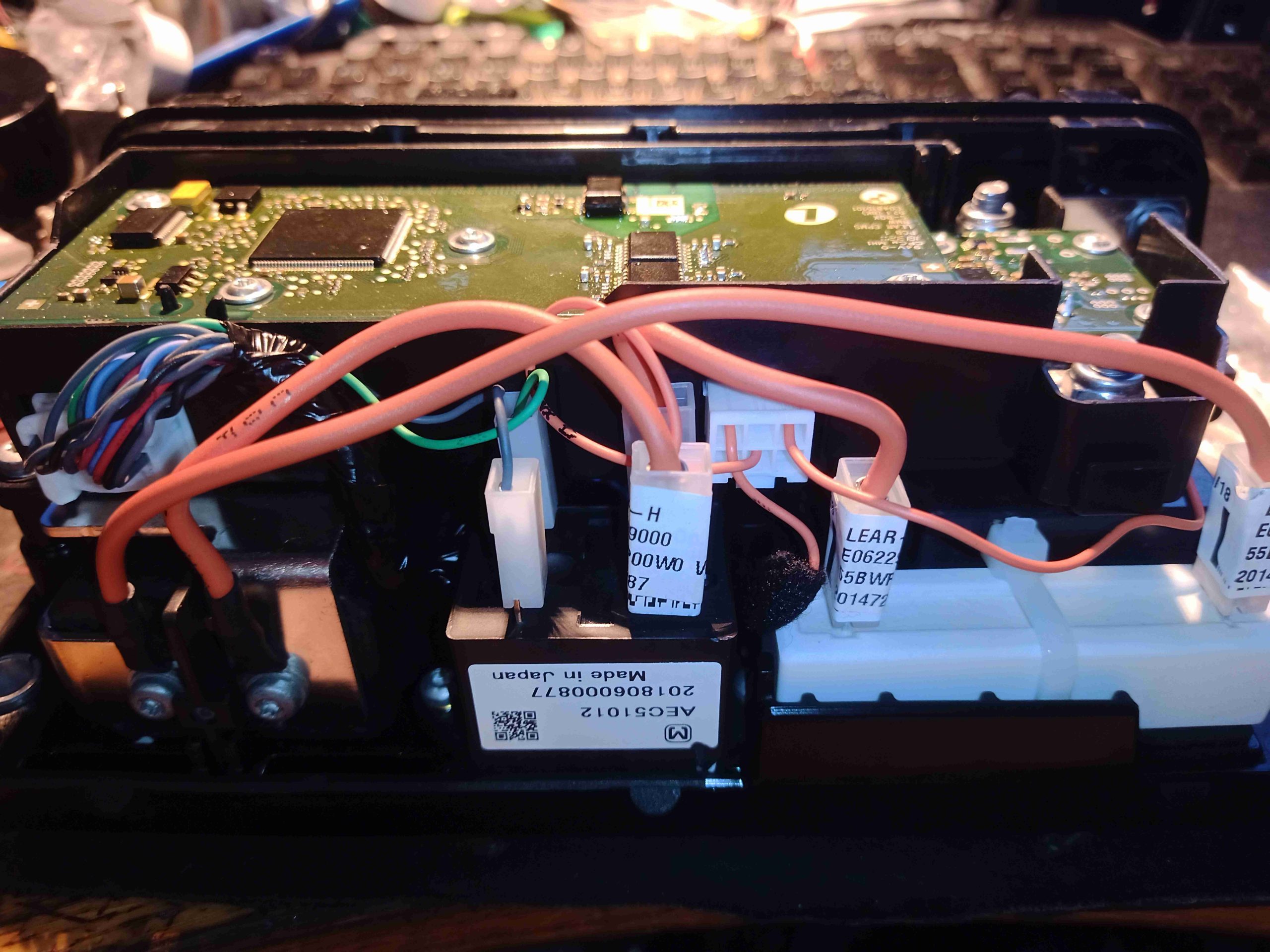
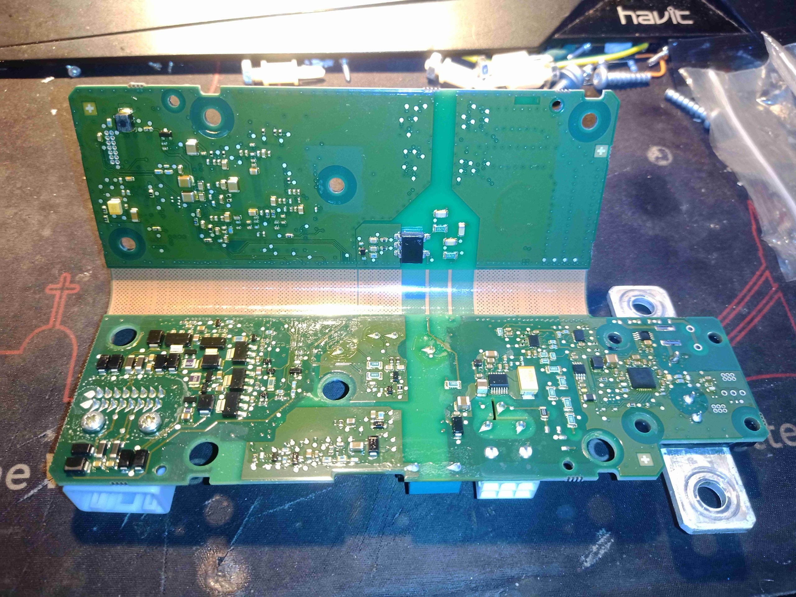
The back of the connector PCB has some passive components, but not much else. There’s the connections for the NTC at the bottom right of the board. There is an IC on this board, on the other side, but without desoldering all the pins, it’s not possible to see properly as it’s mainly hidden by the connector frame.

Battery Indicator LEDs

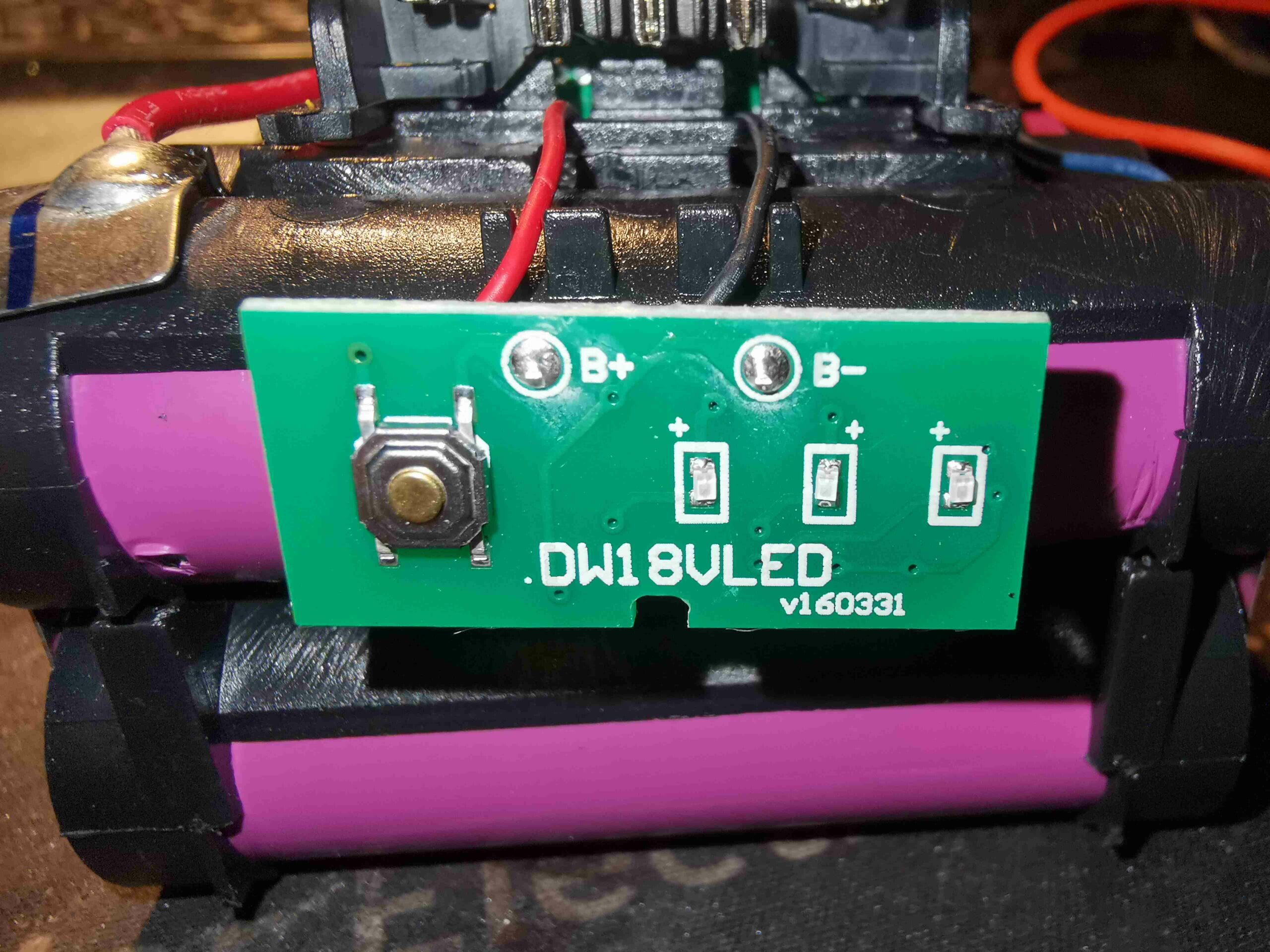
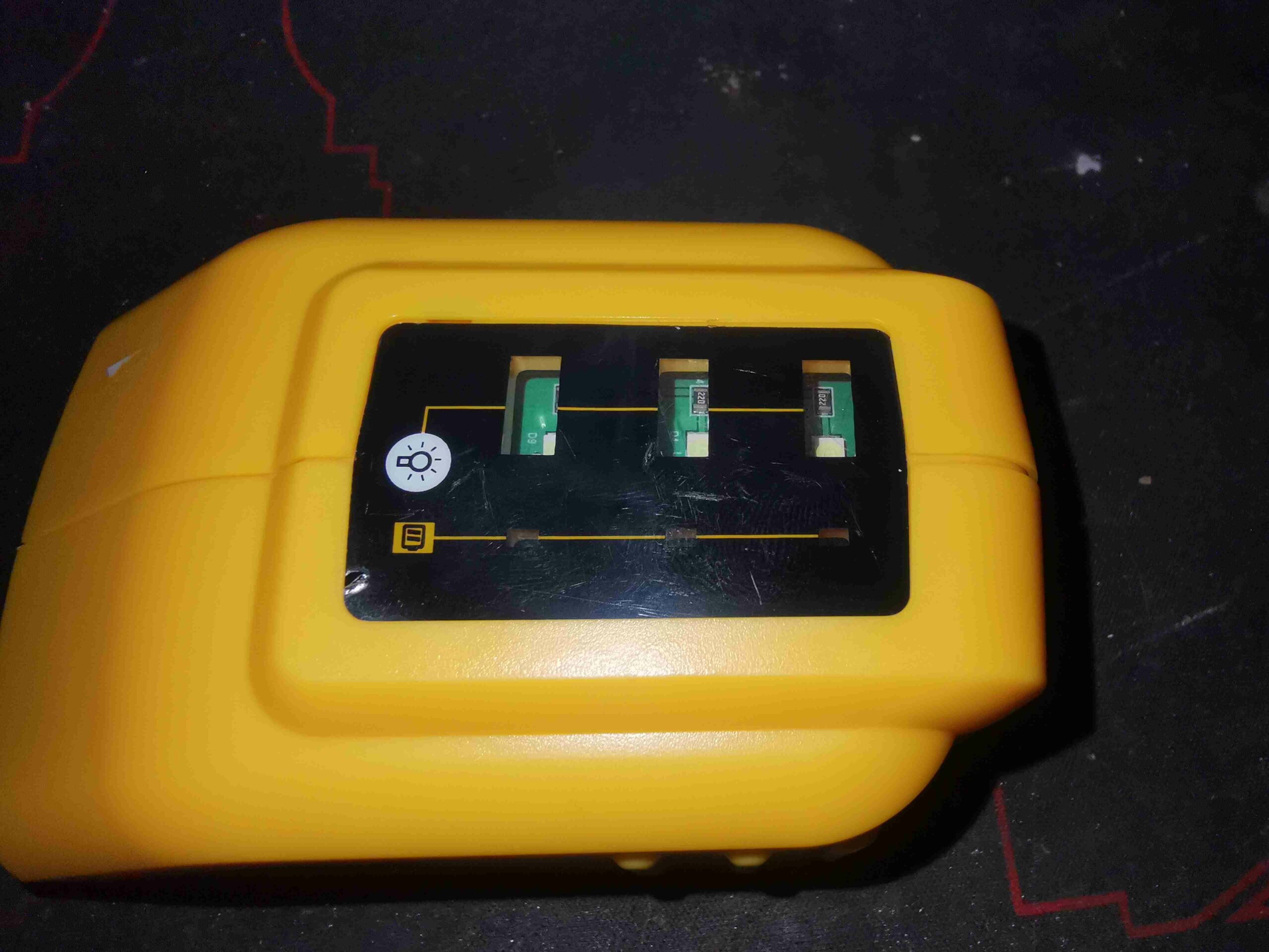
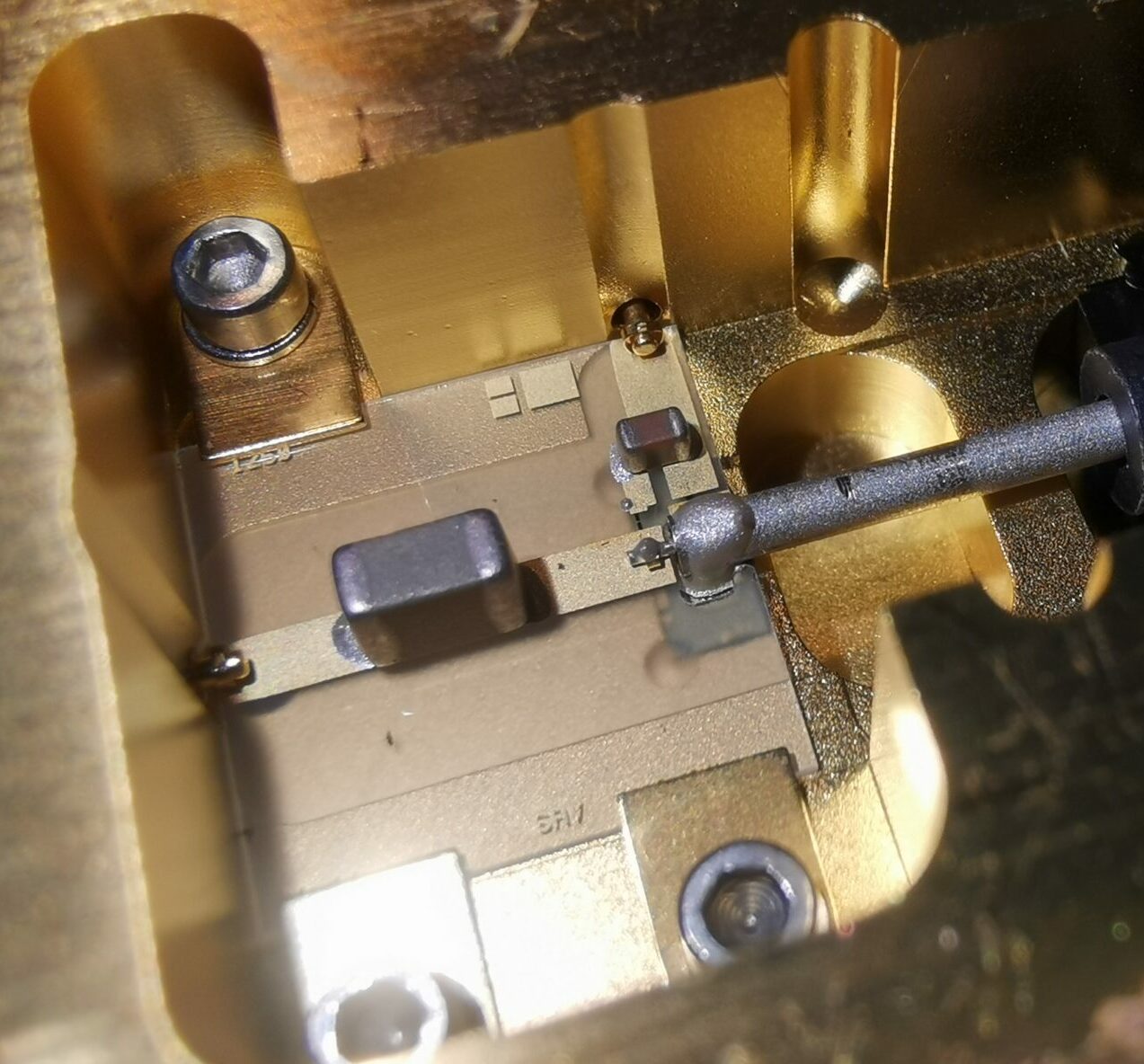
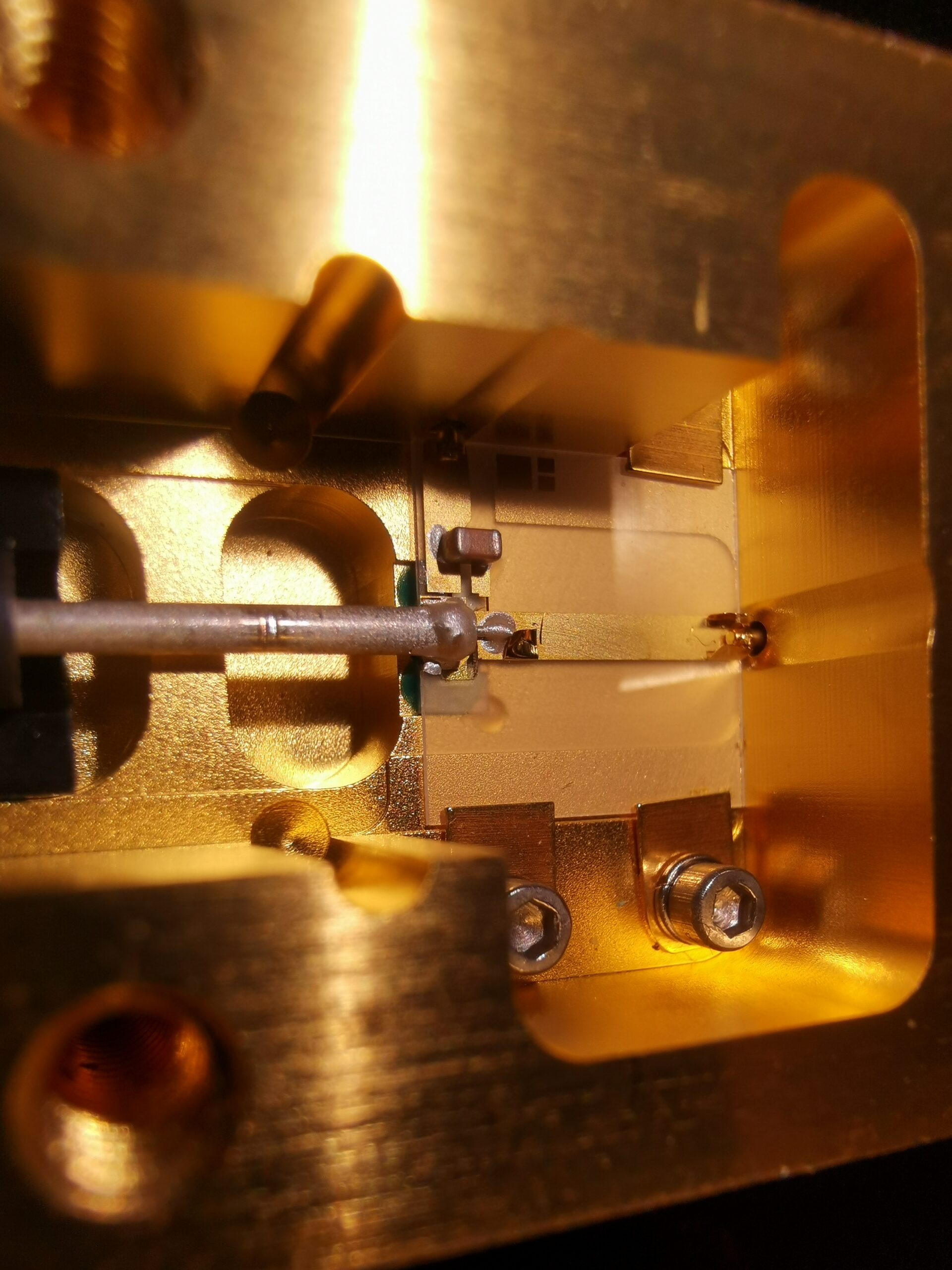
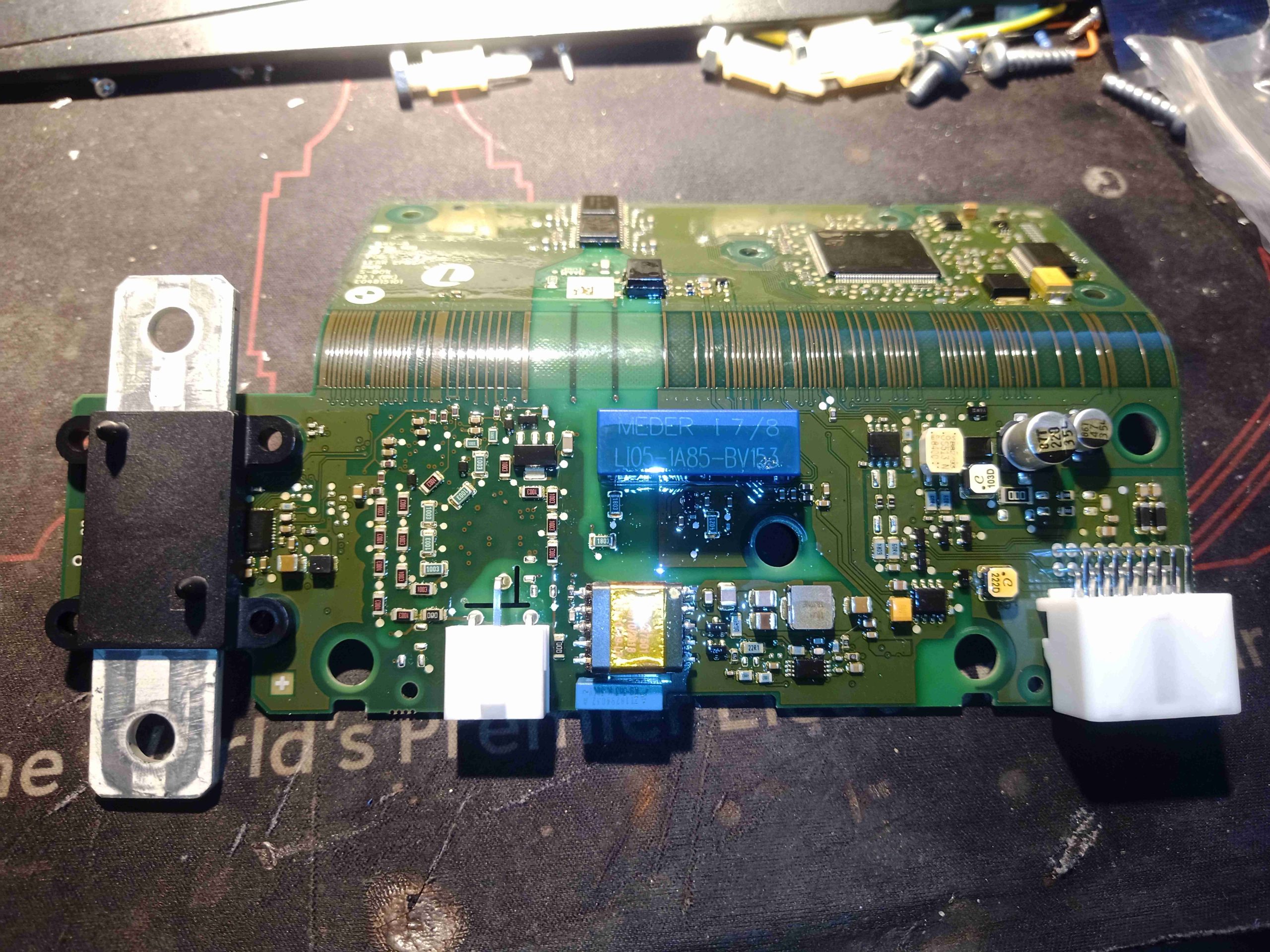
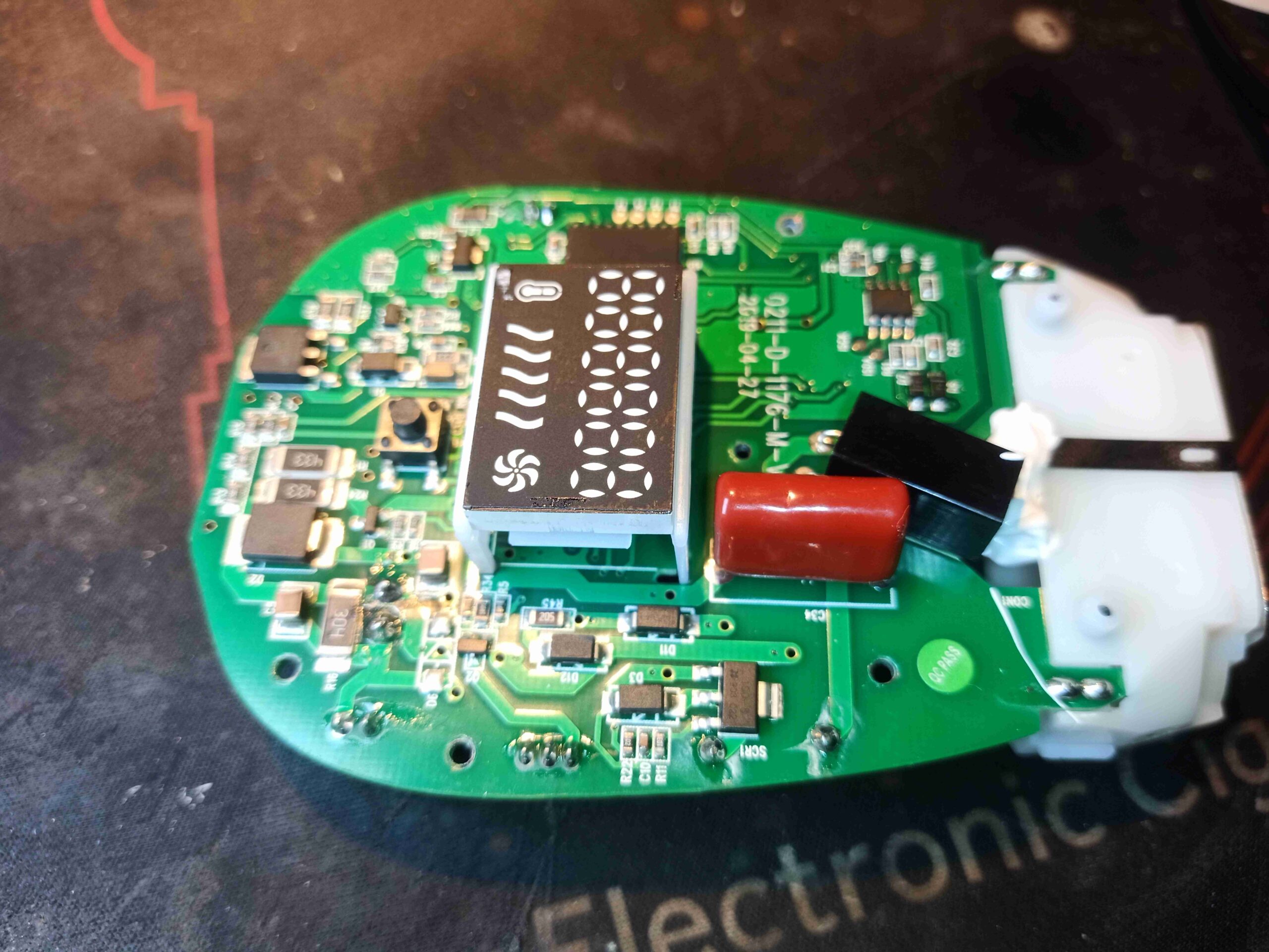
Not much on the front of the battery meter board, apart from the 3 bright green LEDs and the tactile switch.

Battery Indicator Components

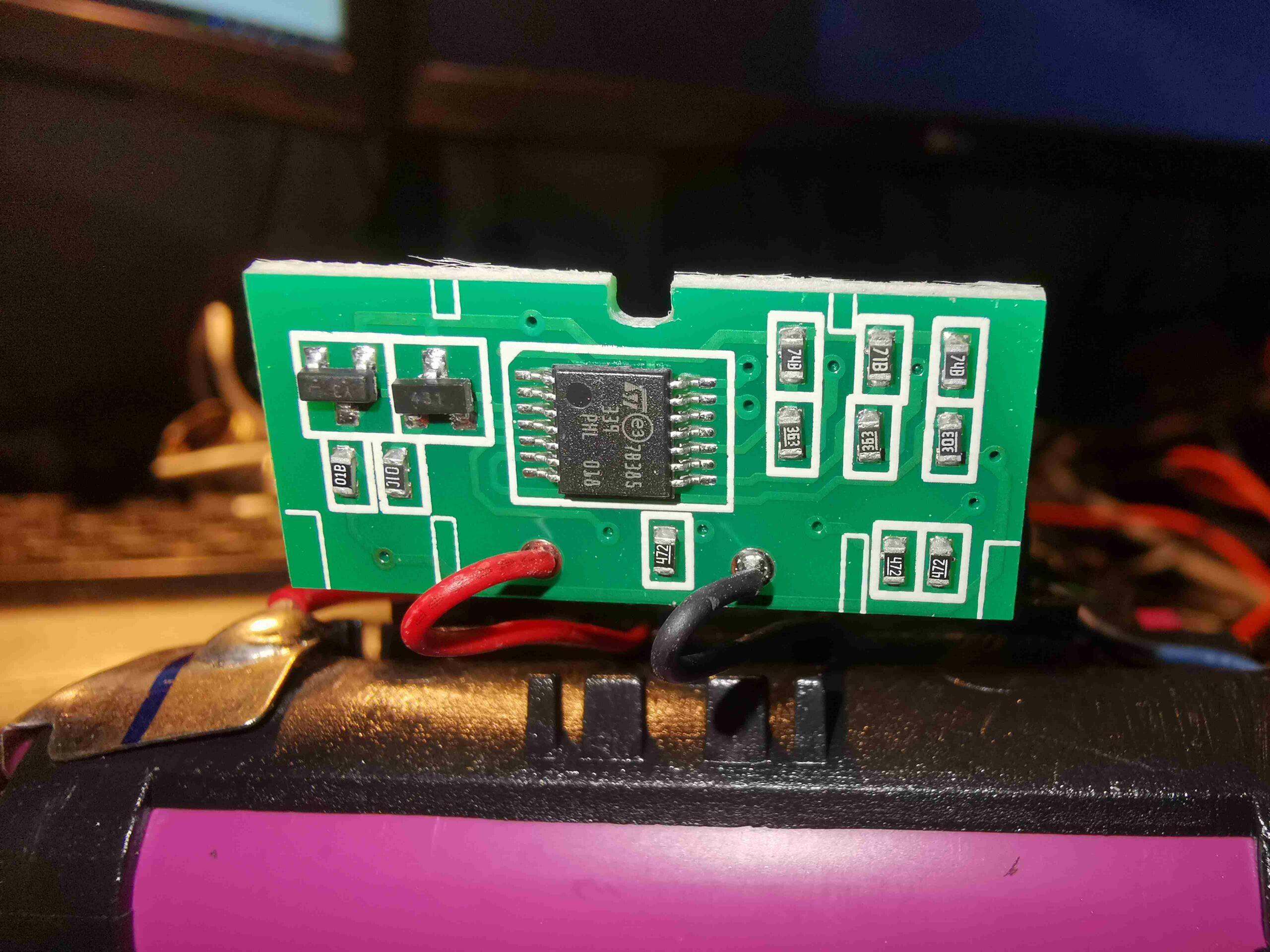
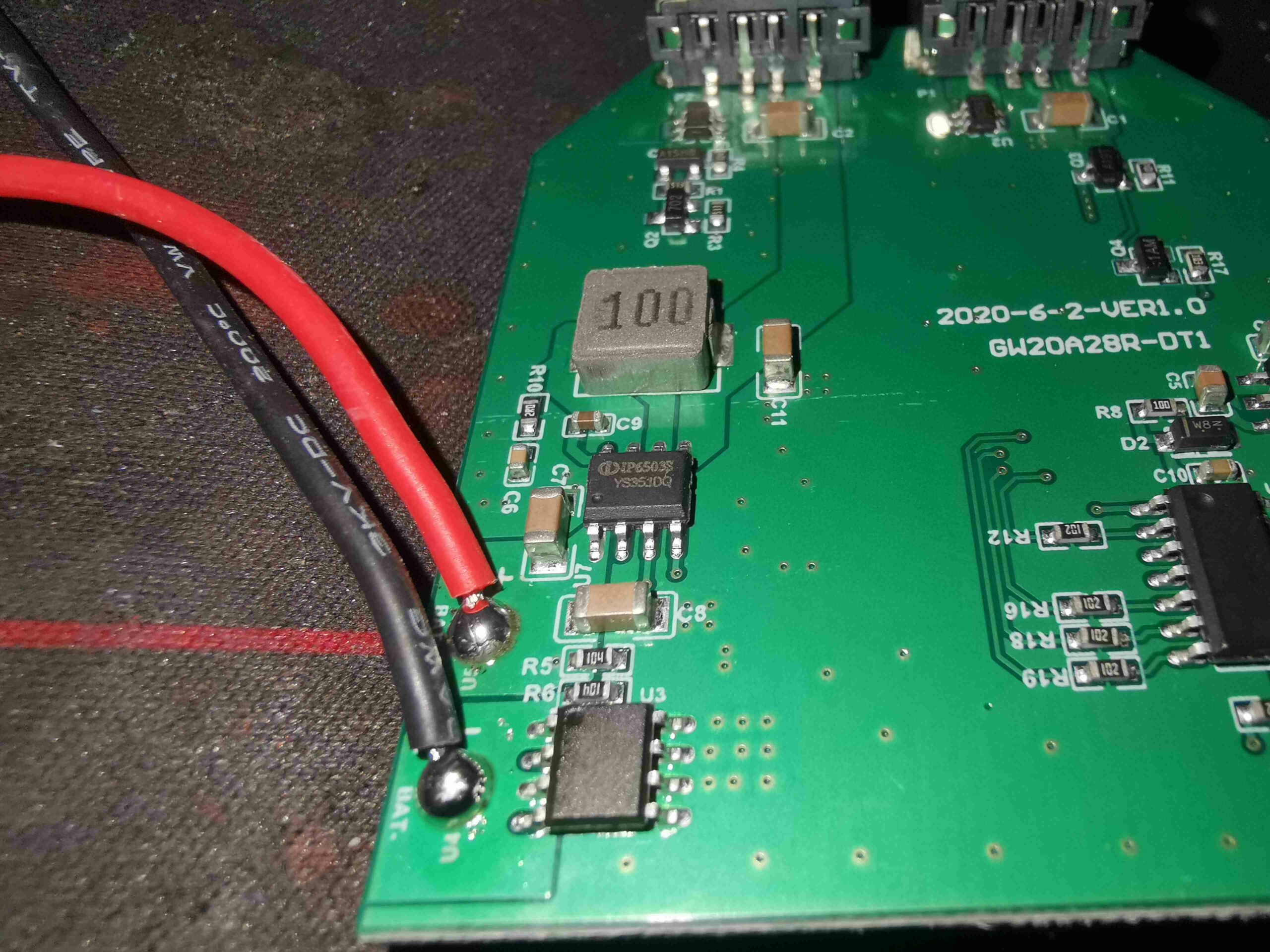
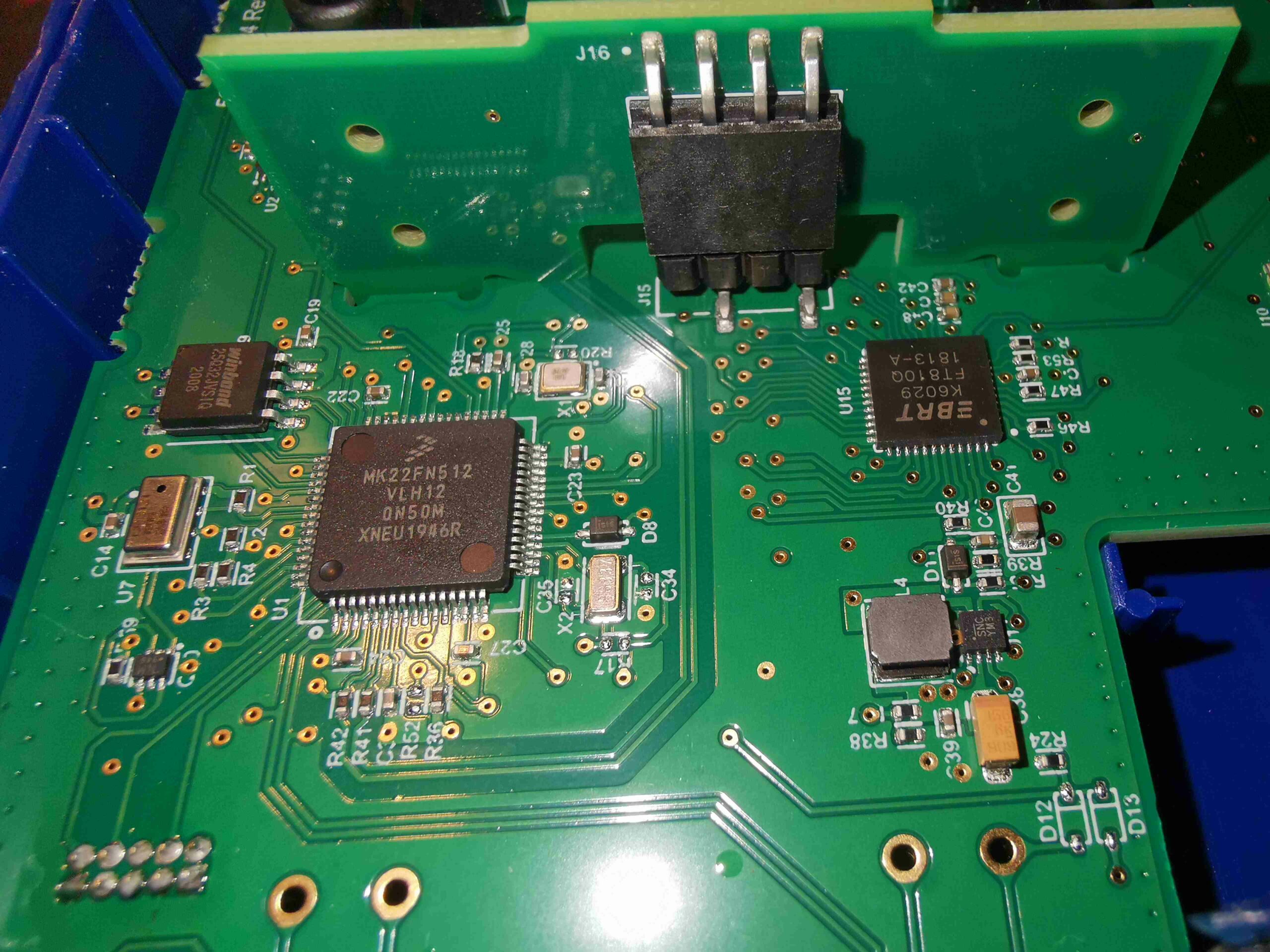
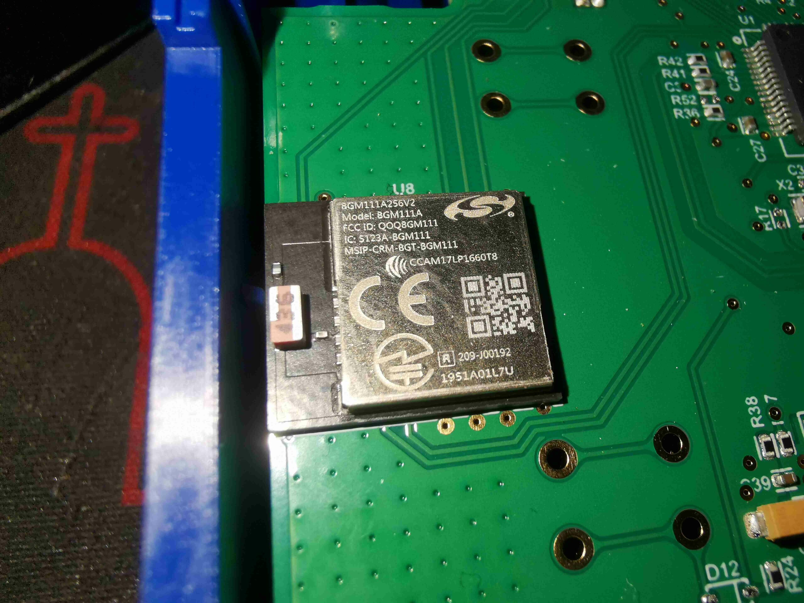
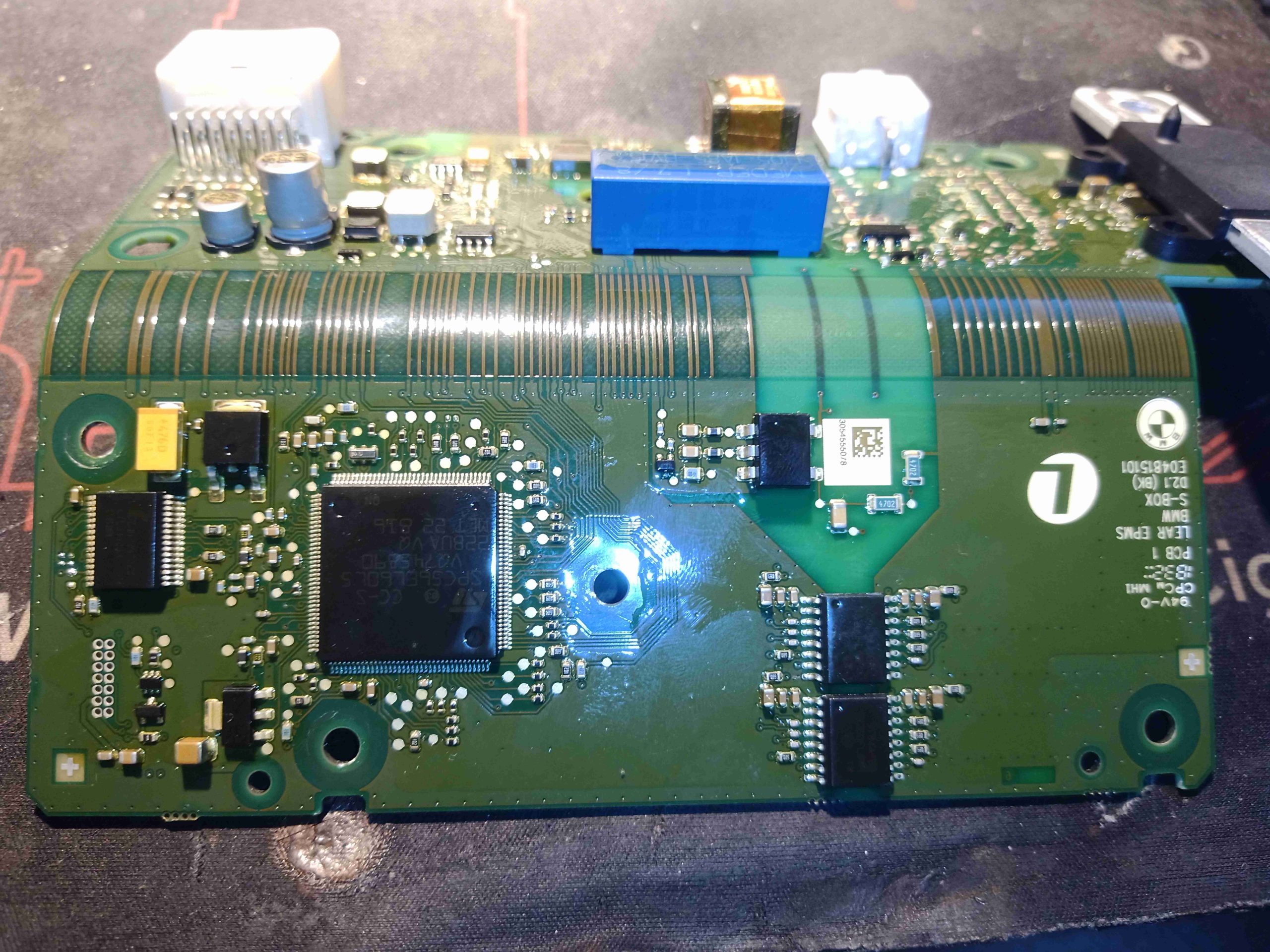
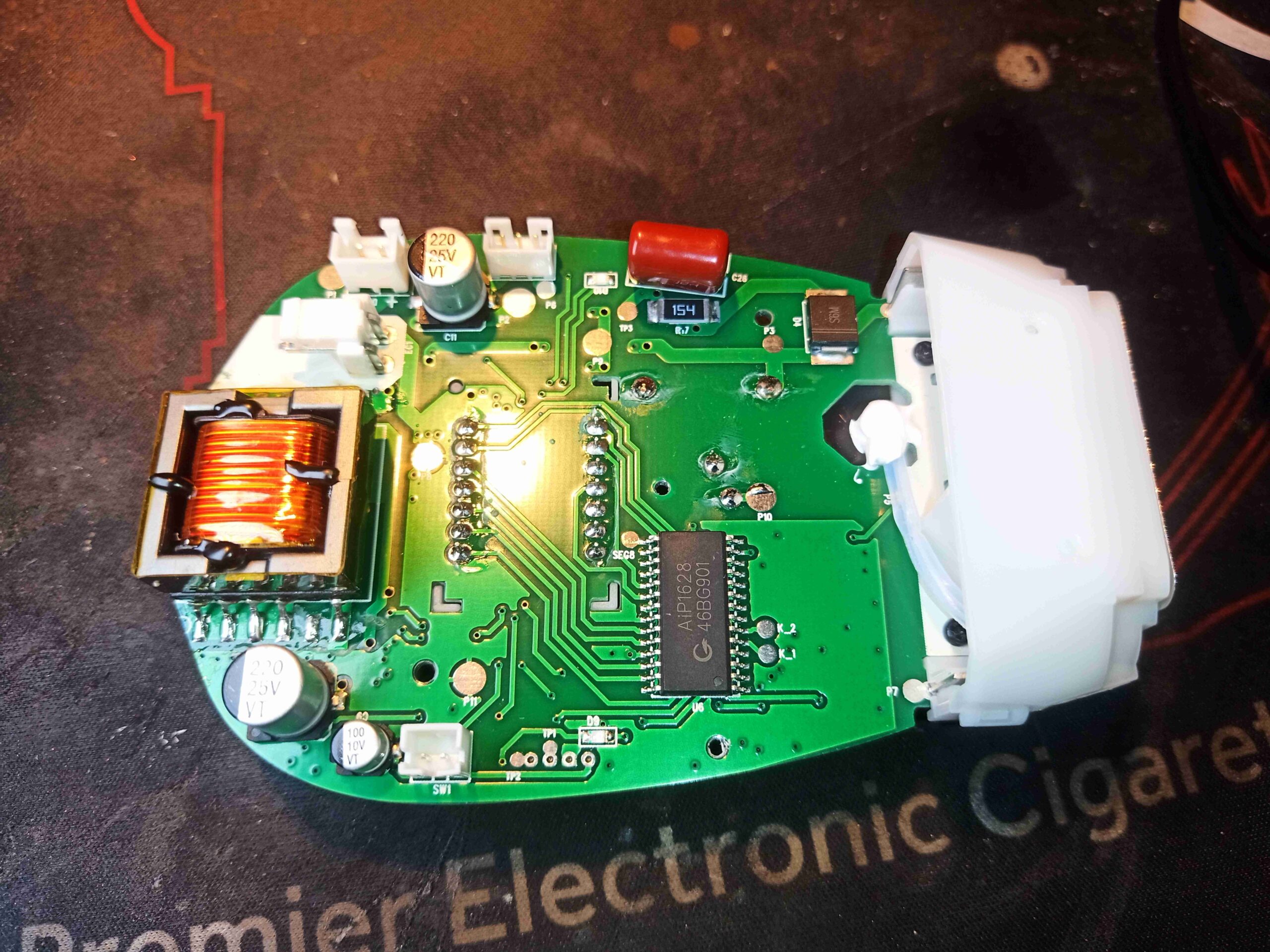
The other side has a small ST microcontroller, a TL431 shunt reference, and some other passives.

Cell Links
Cell Links

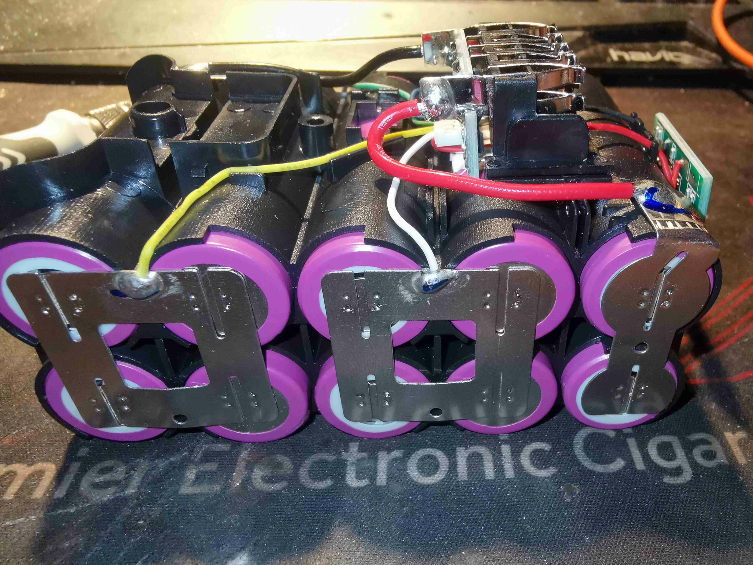
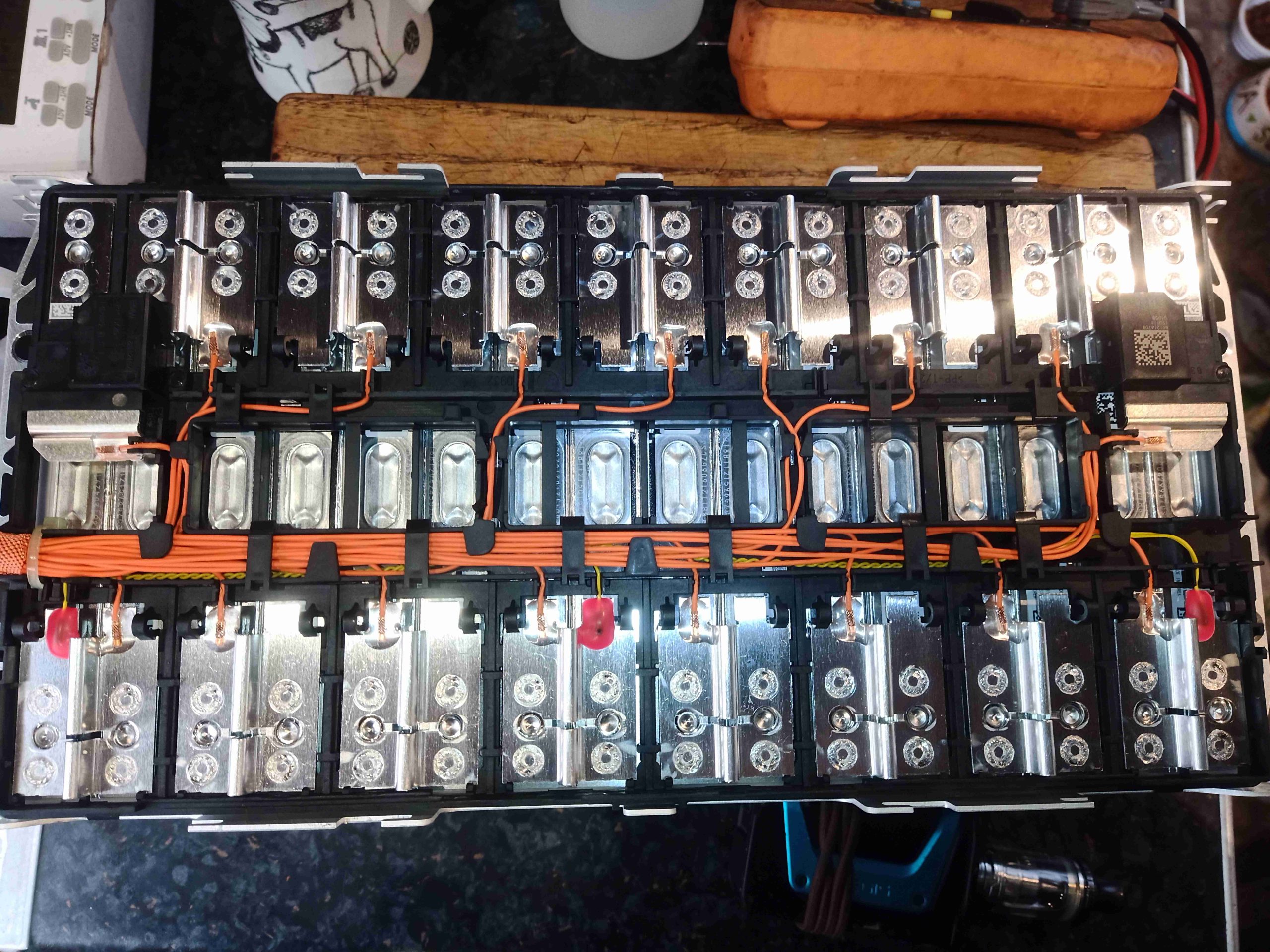
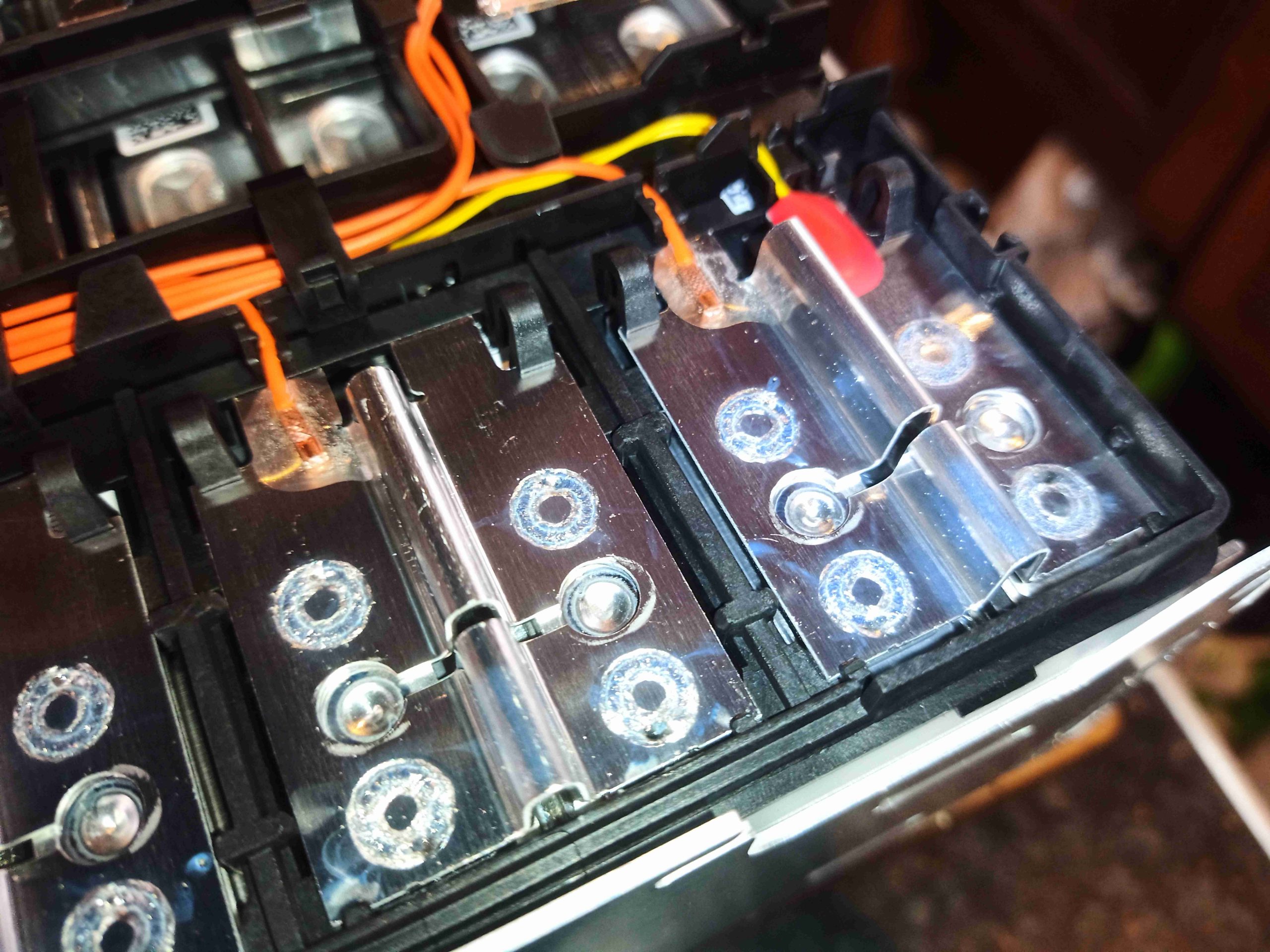
All the cells are linked together with hefty interconnects, as expected for a high current pack. This is laid out as a 5S2P configuration, giving 21V max, 15V flat. Unfortunately I can’t see any markings on the cells – they may be off brand, or pulls from other products.

I figured as I always do with Chinese battery packs that the stated capacity of 6Ah was too good to be true, so I ran my usual cycle tests to see what the real capacity was, and was met with the following results:

Cycle NumberPack APack B
13969mAh3917mAh
23963mAh3947mAh
33961mAh3956mAh
43953mAh3959mAh

As can be seen from the table, these packs are 4Ah, not 6Ah. 2Ah cells sort of make sense for a pack like this, as the high-current capacity cells tend to be a lower capacity.

Posted on Leave a comment

Clone DCB090 DeWalt USB Battery Adaptor Teardown

DCB090 Clone USB Adaptor

Since I got my new DeWalt combi drill, I needed a way to charge the batteries without having to resort to sticking blade terminals into the pack connectors – I didn’t purchase the branded charger, mainly due to cost. I also have a very capable multi-chemistry charger that handles multi-cell lithium packs with no issues, so I saw no need to replicate things. This little gadget was ordered just for it’s main pack connector; I can then use this to make up a charger adaptor cable. What this normally does is allow the use of DeWalt XR battery packs to charge mobile devices via 5v USB outputs, so there’s going to be some kind of DC-DC converter in here. There’s also a “charge level indicator” built in, which doesn’t actually do anything sensible – even on a flat battery pack, showing a single LED on it’s charge indicator shows the full 3 LEDs on this unit.
The remaining feature is a trio of white LEDs to function as a torch, but it’s less than stellar in the brightness department. Given that there’s not much in the way of control inside the battery packs themselves, I reckon this unit could actually overdischarge a pack, causing damage.

Torch LED & Charge Indicator

The top of the unit has a large label with windows in for the various LEDs, and a pad covering the tactile switch to operate the torch function.

Label
Label

The label on the side indicates the unit will operate down to 10.8v, good for the 3S packs, as well as the 18/20V packs.

Pack Connector
Pack Connector

Here’s what I was after – the battery pack connector. This has the full compliment of pins for all the balance taps too.

Casing Opened
Casing Opened

Removing a label, and a single screw gives access to the internals. There’s not much in here apart from a large PCB, with a few components.

Main PCB
Main PCB

The PCB is pretty sparse. There’s a microcontroller in the top right corner that does the torch LED switching, and the “battery indicator LEDs”. This is completely unmarked, which is very common now for Chinese microcontrollers. The only way I’m identifying this one is via a decap operation on the IC!
The USB ports have MOSFETs in their negative pin paths, probably to switch off the ports if they’re overloaded. The data pins are bridged together on one port, and connected to the DC-DC converter on the other port.

DC-DC Converter
DC-DC Converter

The main DC-DC converter IC is in the bottom right corner of the board, next to the input pins. This is an IP6503S multi-protocol USB charging converter, with a 24W power limit. This explains why the data pins of one of the USB ports is connected back here – it’s doing some communications with the connected device for fast charging. Chinese datasheet below.

Posted on 4 Comments

Yellow Jacket Titan P51-870 Digital Manifold Teardown

Front Panel & LCD
Front Panel & LCD
Front Panel & LCD

New tool time! I figured now I’m a fully ticketed member of the F-Gas community, I’d treat myself to passing the course by buying a decent set of refrigeration gauges. This is the Yellow Jacket P51-870 Titan manifold, a fully digital unit with all the useful functions built in. Basically an electronic module attached on the top of the standard Titan manifold, this unit performs all the regular functions I’d normally need either a calculator for, or other tools. The front of the unit has just a power button, LED & a large resistive touch TFT panel for display.

Rear Panel
Rear Panel

The rear panel has the ports for charging the internal battery, which is micro USB – this is also used to download log data to a PC from a system processing run. There are 4 3.5mm jacks for the external temperature probes, and vacuum sensor.

Rear Cover Removed
Rear Cover Removed

Removing 4 Torx screws in the back panel allows the clamshell case to come apart, showing the mainboard, and the pressure transducers screwed into the manifold. The aux jacks & the USB charging & data port are supported on small vertical PCBs plugged into the mainboard via 0.1″ headers.

Main PCB Overview
Main PCB Overview

With the pressure transducers unplugged from their looms to the mainboard, the module is free from the manifold section.

Main Microcontroller

The muscle of the operation here is a Freescale (now NXP) Kinetis K2 Series MK22FN512VLH12 ARM microcontroller. With a Cortex-M4 core at 120MHz, there’s a bit of beef here. The LCD & touch overlay is controlled by a Bridgetek FT810Q Embedded Video Engine. The video controller communicates with the microcontroller via SPI, and the LCD via parallel RGB. There’s some SPI Flash memory up on the left, for log data storage, a Winbond W25Q32JV 32Mbit part. Just under that is a pressure sensor, which I’ve been so far unable to pull a part number off. This is required to assist in calibration of the main pressure transducers.


Switching Section
Switching Section

In the top right corner of the board is a 74HC595 shift register, with quite a few discrete transistors & diodes hanging around it. I suspect this is used to switch between two vacuum sensors when both are plugged in – from looking at the waveforms present on the sensor interface, the power does appear to be switched ON/OFF on a single sensor at about 1Hz.

My guess at the moment is that the sensor communications are over I²C, by the 4-wire connection, and the very obvious clock & data line on the connector, but I haven’t yet looked deeply into this.

Main Power Supplies
Main Power Supplies

Next to the battery connector (the battery itself is a single LiPo pouch cell, double-sided taped to the front shell, behind the display), are a selection of DC-DC converters, providing all the required voltage rails. No doubt there’s lithium charging control going on here too.

Bluetooth Module
Bluetooth Module

Wireless connectivity is provided for by a Silicon Labs Blue Gecko BGM111A256V2 Bluetooth 4.2 SoC module. These are also fairly powerful parts, with a full ARM Cortex M4 microcontroller hiding inside, clocked at 40MHz. There are as a result two programming headers on this board, in the top left corner, for both this part & the main microcontroller.

Posted on Leave a comment

HP 5087-7048 Directional Coupler Teardown

Directional Coupler
Directional Coupler
Directional Coupler

Time for some more RF component teardowns, here’s a very high quality Directional Coupler from HP, I believe this was part of a Vector Network Analyser at some stage. The main body appears to be made of Brass, but the entire unit looks like it’s Gold plated – the shine is far too good to be just Brass! Connections are via SMA connectors.

Label
Label

There isn’t much on the label to explain what the specifications are unfortunately. Nothing that can’t be found out with a quick look on a VNA though.

Cover Removed
Cover Removed

After removing the 6 Torx screws securing the top cap of the coupler, the internal components are revealed. There is no RF gasket or seal on the top cover, and relies on flat machining for an RF seal.

Internal Components
Internal Components

The internal construction of this unit is a little different from what I’ve seen before in directional couplers. The arrangement is usually parallel copper tracks on a suitable RF substrate, but in this case, HP have used a very small diameter Coaxial cable, covered with ferrite sleeves on the outer shield. The large square block in the middle is rubber, and may just be to stabilise the assembly. It may also be loaded with ferrite powder to give some RF properties too.
The ferrite cores are secured in place with beads of black silicone, again probably to prevent movement under vibration.

Input End
Input End

The input of this coupler is AC coupled via a capacitor, and then fed into the centre core of the Coax. The forward power output pin, visible at the top of the track, is coupled to the centre core of the coax by a tiny carbon track making up a resistor, via another ceramic capacitor. The track is more directly coupled via another carbon trace to the outer shield of the Coax. I believe this coupler is damaged, as the carbon trace that goes via the capacitor has a break in the centre, but the coupler does seemingly still work.

Output End
Output End

The other end of the coupler is very similar, although with no main line coupling capacitor, it’s direct fed to the SMA here. The reverse power output is connected the same way as the other, with a network. The carbon trace here though doesn’t have a break.

Posted on Leave a comment

Housekeeping – Moving Servers!

The time has come yet again, to reduce my rack footprint. For the last 5 years or so, this blog has been hosted on a small HP MicroServer Gen8, as at the time I needed a new host machine, and for some reason they were going by their thousands for rock-bottom cash. That machine has faithfully worked 24/7, without many gripes, but it’s time to concentrate things down to requiring less physical hardware.

What’s enabled me to sort this out, is performing a hardware rebuild on my main file server, which has for years been a Heath-Robinson affair.

GPU & RAID Cards
GPU & RAID Cards

Well, the file server got ANOTHER upgrade, quite quickly. The motherboard was replaced again, this time with a new board, new Corsair RAM & a new Intel i7-9700F 8-Core CPU. As this server also runs video transcoding services, the tiny GPU got pulled & replaced with a spare nVidia GTX980 I had just for that task. My LSI RAID cards are still used as HBAs, just as JBOD, since Linux is running the main disk array via mdadm.

Server Internals
Server Internals

Once this upgrade was completed, with space for resource expansion – the motherboard supports up to 128GB RAM, at the moment there’s 32GB in there due to the eye-watering cost of RAM at the present time – there was scope for running some Virtualisation for other services.

Still running OpenMediaVault, based around Debian 10, I installed the Kernel KVM modules & QEMU, along with Cockpit for control. Going this route was dictated by VirtualBox not being directly supported in Debian 10, for reasons I don’t know.

Once all this was installed, and a network bridge set up for the VMs through a spare network interface, I brought up a pair of Debian 10 servers – one for PiHole which had up until this point been running on a spare Raspberry Pi for the last 6 or so years (I think the SD card is totally shot at this point!), and one for my web App server.

At the moment, all the VMs are running from the main RAID6 spinning rust array, which is a little slow, but the next planned upgrade is to move the VM subsystem to it’s own RAID10 array of disks, hopefully speeding things up – there are just enough SATA ports left on the motherboard to accommodate 6 more drives, and with both 5.25″ disk bays being available for caddies, this should be a simple fix.

As a result, I’m down to a single server powering my entire online domain, and a reduction in power usage!

Posted on Leave a comment

BMW 5 Series Battery Pack – Reconfiguring The Modules & Wiring

Mounting Board
Mounting Board

Now the cell modules have been removed from their original home, it’s time to get them repurposed! A custom mounting board has been constructed from timber, and the modules mounted on them. To say this assembly is heavy would be an understatement – it’s barely a two-man lift!
As assembled in the car, the pack as 96S1P, with every cell in series. As we need a low voltage bus, the modules have been reconfigured for 4S4P, in total this makes 4S24P with all 6 modules bussed together. As the cell interconnects are laser welded, some ingenuity was required here.
It turned out the best method (and the safest, to avoid any swarf shorting out cells!), was to use a grinder to cut off the top of the loop on the aluminium interconnects, separating them.

Battery Bus Links
Battery Bus Links

12 5-way bus bars have been installed on the board, and 25mm² cable links them together. To get the angry pixies from the cell modules, 8mm² flexible silicone cable has been used, 4 links to a bus bar. This setup should provide more than enough current capacity.

Cell Connections
Cell Connections

Here can be seen the cell interconnects – and the grinder cuts to separate them where required to break the module up into 4S strings. As the interconnects are Aluminium, special solder was required to get the copper cables soldered down, in my case I used Alusol 45D solder, which contains a very active flux capable of stripping the oxide from the Aluminium.

Batteries Wired
Batteries Wired

Finally, here is the new pack, all connected together. All that needs to be done now is the balance wiring loom, which will allow the BMS to sense each cell voltage individually, and connection of the BMS, Coloumeter & fuses, this will all be covered in a future post!

Posted on Leave a comment

Surprise Mouse!

Well, while working on the boat’s engine, I was surprised by this little sod, who’d managed to crawl into the air intake skin fitting on the transom, and got very irritated at the engine being fired up! How the little dude avoided getting sucked into one of the cylinders, I have no idea! The wee mouse was recovered from the air intake & released on the towpath.

Posted on 1 Comment

Epever Tracer 4210AN MPPT Charge Controller MOSFET Repair

Failed FETs
Failed FETs

Here’s some damage to a 1-week old Epever Tracer 4210AN MPPT Charge Controller, where some of the power FETs have decided they’ve had enough of this world. These are Alpha & Omega AON6512 N-Channel Enhancement devices, rated at 30V 150A. From probing around, these seem to be on the battery bus for output protection – they’re just used as power switches in this application. The controller did work in this state, but charging from the solar input was accompanied by a very strong burning PCB smell.
I’m not sure what caused the failure, but as they’re all in parallel, if a single device failed, then it’s likely that the remaining parts having to then compensate for the extra load put them under enough stress to cause a failure.

Cleaned PCB
Cleaned PCB

The hot air gun was used to get the old parts off the board, which had got hot enough to fully oxidise the solder on the thermal pad, along with causing a bit of damage to the PCB itself. I scrubbed the board with a fibreglass pencil to try & get all the Magic Smoke residue off, along with any oxide on the copper. There has been some flaking of the soldermask, but luckily only between connected pads, and not around the gate pads. There was some unfortunate collateral damage to the main fuses, with minor melting of the plastic case, but they’re still electrically intact.

Reflowed Replacements

Replacement MOSFETs were sourced from Farnell, in this case ON Semi NVMFS5C628N parts, rated at 60V 150A. Since these parts are in a DFN package, solder paste & hot air was used to reflow them back onto the cleaned pads, and then everything checked for short circuits.
The replacement FETs have slightly higher RdsOn resistance, but this shouldn’t be an issue.

Posted on Leave a comment

BMW Series 5 Hybrid Battery Contactor Pack Teardown

Main Connectors
Main Connectors

Now it’s time to dig into the main contactor pack from the hybrid battery I tore down in a previous post. This unit contains the main output relays, precharge components, current measurement & protection. It’s pretty heavy, which isn’t surprising when you realise how much copper there is in this thing! Manufactured by Lear Corporation in the US, this is a seriously heavy duty piece of electrical engineering.

Cover Removed
Cover Removed

Once the cover is popped off, the first thing is a large PCB on the top, and some low current wiring. Not much to see yet.

Control PCB & Current Sensor

The main control & current measurement PCB is on the top of the unit, in a plastic frame. This is a complex arrangement in itself. Unfortunately I’ve not been able to identify any of the main components on here, as everything is conformal coated, so the numbers are obscured!

Main Control PCB Top

Removing the assembly from it’s plastic frame reveals a flex-rigid assembly, which is normally folded in half. The main CPU is on the top layer, and most of the power supply & measurement electronics on the bottom. There’s some serious isolation here on the right as well.

Main Control PCB Bottom

The bottom has the connectors, and some power supply components. The main current shunt is on the left, this would be in the negative return side of the main battery bus.

Main Control PCB Reverse

Not much on the backside of the assembly, apart from a few transistors & passives.

Control PCB Removed
Control PCB Removed

Once the control PCB assembly is removed from the main frame, the high current bus bars become visible. There are 3 switching devices in here, two for the main battery bus, and a smaller one for the precharge function. There’s also a main fuse hiding in the middle.

Main Positive Contactor

The main battery positive contactor is tucked in on the left side, with the precharge leads across it’s contacts. This normally isolates the car from the batteries when open.

Precharge Components

Precharging is dealt with by this collection of components. A smaller relay, and a large ceramic 15Ω resistor limit the current that can be drawn when the vehicle is enabled. Closing the main contactors first would potentially cause damage due to the enormous inrush currents caused by the large filter electrolytic capacitors in the traction inverters.

Main Battery Fuse
Main Battery Fuse

The main battery fuse, in the DC + line from the cell modules is a 350A rated unit, 450v DC. Being a HRC type, this is capable of breaking 6kA under fault conditions.

Panasonic AEV14012 Contactor

Here’s one of the pair of main contactors, Panasonic AEV14012 400v DC, 120A rated units. These are serious devices, having a hermetically sealed ceramic capsule around the contacts, and a Hydrogen filling! 

Main Contacts
Main Contacts

Connections are made via big copper slugs, with M4 screws in the ends. There’s a barrier between them to protect against flashover.

Ceramic Capsule
Ceramic Capsule

Pulling the top plastic cap off reveals the ceramic capsule containing the contacts. This is the Hydrogen filled space of the contactor. The reason for the hydrogen fill is arc quenching.

Arc Magnets
Arc Magnets

The contact capsule sits in a permanent magnetic field, provided by these small ceramic magnets. These assist in pulling any arc towards the ceramic walls of the contact capsule, helping to cool & extinguish it.

Posted on 4 Comments

BMW Series 5 Hybrid Battery Pack Teardown

Here’s something I didn’t think I’d be doing! Here’s a teardown of a BMW 5 Series G30 530E Hybrid Battery pack – a monster 351V, 9.2kWh Lithium pack, obtained for it’s cells to replace the boat’s aging lead acids.

This is something I didn’t have the safety gear to do right of the bat – opening one of these packs is a potentially lethal exercise, with 6 unfused battery modules in series, quite capable of blowing pieces off a nice conductive sack of salt water like a person. Cue the purchase of high-voltage rated gloves for protection, just while I got the pack split into something more manageable.

Needless to say, the combination of current capacity & voltage present in EV or Hybrid vehicle battery packs is nothing short of lethal, and these units should be treated with considerable respect.

Hybrid Battery Pack
Hybrid Battery Pack

Here’s the beast of a battery. Enclosed in an aluminium cast housing, it’s very heavy, and definitely not a one-man lift!

Cover Removed
Cover Removed

After removing the top cover, secured by combination Torx/10mm hex bolts, the internals of the pack are visible. There’s no sealant on the cover, just a large rubber gasket, so this came off easily. There are 6 individual modules in this pack, all wired in series with massive links. There’s also a cooling system for each battery module, supplied with refrigerant from the car’s AC system – there’s a TXV mounted on the side of the battery pack. I didn’t see any heaters present, but I don’t know if BMW have done any neat reverse-cycle magic to also heat the modules if required using the AC system on the car.

Left Side Modules
Left Side Modules

The modules are arranged 3 to a side, double-stacked at the back, then a single module at the front. The pack would normally sit under the rear seats of the vehicle, hence the unusual shape. The refrigerant lines going to the evaporators on this side of the pack can be seen in the bottom right corner.

Output Cables & Contactor Pack

The main contactor pack is on the left side, just behind the massive DC output connector. I’ll dig into this in another post later on.

Right Side Modules
Right Side Modules

The right side of the pack is arranged much the same as the left, the main difference here being the battery ECU is tucked in at the top here, along with the interface connector to the car, and the refrigerant lines to the TXV on the outside, which I’ve already removed. Each module has a cell balance control unit, in this case one is mounted on the top of a module, and on the side of the module in the lower right corner.

Cooling Evaporator
Cooling Evaporator

Once all the modules have been removed, the evaporator matrix is visible on the bottom, a series of very thin aluminium tubes, designed for the best contact with the aluminium frame of the battery modules.

Module Cell Layout
Module Cell Layout

Popping the plastic insulating cover off the battery module reveals the internal construction. I’ve not been able to find exact data on these cells, but I’m assuming them to be a similar chemistry to the ones used in the BMW i3 packs, so 4.15v Max, 3.68v nominal, 2.7v Minimum. The alloy frame itself is of laser welded construction, and there are 16 cells in series per module, giving about 58.8v per module. These will need to be reconfigured as 4 sets of 4 cells in series for 14.72v.
All the individual cell taps are nicely loomed down the middle of the module to each cell, and there are 3 temperature sensors per module (the red epoxy blobs).

Cell Welded Links
Cell Welded Links

The individual cell links are laser welded to the terminals of the cells, so this does make life a little more difficult when it comes to reconfiguring them. The links appear to be made from Aluminium, so soldering is going to be a bit more tricky than usual.

Posted on 4 Comments

USB Powerbank Efficiency Testing

These days USB powerbanks are very common – ranging in capacity from about 1Ah, to about 20Ah. Internally, they’ve all got much the same format:

  • Lithium Ion cylindrical or Lithium polymer pouch cells for energy storage
  • DC-DC boost converter
  • Microcontroller & LED Battery Gauge Display
  • Lithium cell protection & charge control

As the maximum voltage of a lithium cell for common chemistries is 4.2v, there needs to be a DC-DC converter to boost the voltage up to 5v for the USB ports – There are dedicated chipsets designed for powerbank use available everywhere for this part, and this section is going to be the most energy-wasteful part of the system.

To get a handle on the discharge efficiency of these units, I ran some tests with a constant current load, on different powerbanks from different manufacturers. All were in the range from 5Ah-20Ah, and all had ports rated for 2.1A Max output current.
The load was set for a nominal 2A current, and the powerbanks were fully charged before a discharge cycle. All powerbanks were in new condition to ensure that age-related degradation of the cells wasn’t going to be much of a factor.

Without further ado, here’s some test results:

Nameplate Capacity (Wh @3.7v Cell Nominal)Nameplate Capacity (Ah)Measured Capacity (Wh, Calculated @5V Output)Measured Capacity (Ah)Ah Efficiency %
44.4Wh12Ah31.656.33Ah52.75
37Wh10Ah33.86.76Ah67.6
74Wh20Ah56.511.3Ah56.5
22.2Wh6Ah17.93.58Ah59.67
18.5Wh5Ah15.043.01Ah60.2
18.5Wh5Ah12.452.49Ah49.8
22.2Wh6Ah193.80Ah63.33
37Wh10Ah30.856.17Ah61.7
55.5Wh15Ah48.69.72Ah64.8
18.5Wh5Ah15.253.05Ah61

Overall, these efficiency numbers are pretty poor with an average of 59.735% across these 9 samples. I expected at least high 80’s for efficiency on powerbank DC-DC converters, which must be pretty well specialised for the input voltage range by now. I suspect this is mostly to do with keeping costs down in mass production.

Posted on 2 Comments

IPL (Intense Pulsed Light) Hair Removal Device Internals

IPL hair removal is rather similar to laser hair removal – high energy photons are directed into the hair follicle to heat the cells up until death occurs, stopping the hair from growing. These units use high-energy Xenon flash tubes to do the job, and operate in exactly the same fashion as a camera flash. Here are the internals of such a device.

Mainboard
Mainboard

The mainboard in the top of the unit deals with all the functions of the device. There’s a main microcontroller, which in this case is an unmarked IC. The UI is a simple LED display, showing the number of shots on the tube remaining. These units come with 500,000 shots programmed in. The limit is to prevent the Xenon tube from exploding when it reaches end of life. In the case of these devices, after the counter reaches zero, the unit is disposed of. The trigger transformer is visible at the right of the board, along with it’s capacitor. This is triggered by a small Thyristor at the bottom edge of the board just to the right of the LED display. There are some power handling components on the left side, along with the main switching FET & gate drive IC for the high voltage supply.

There are several power settings, and the power itself is varied by the voltage on the main capacitor, from around 270v to 400v. There’s no dedicated switching IC here – The microcontroller generates a 65kHz square wave, from 0-50% duty cycle to drive the main switching FET. There’s a resistive feedback network to regulate the boost converter’s output voltage.

Mainboard Bottom
Mainboard Bottom

There’s less on the bottom of the PCB, apart from the connections to the PSU, cooling fan, capacitor & trigger button, there is the transformer for the HV supply. At the lower centre, is the driver IC for the LED display.

Flashtube
Flashtube

The flash tube is mostly hidden inside a plastic shroud with an amber filter glass on the front to provide the correct light spectrum. The metal ring around the outside edge is part of a capacitive detection mechanism that prevents the tube firing unless it’s placed against skin. I have no doubt that the intensity of light from these devices could quite easily cause eye damage. Even absorbing the energy into the skin is slightly painful – hitting black tattoo ink with it feels like a needle prick!

Cooling Blower
Cooling Blower

Since the flash tube passes such a large pulse of energy, it is force cooled by this small blower which sits under the mainboard, and directs air into a slot in one end of the tube housing. The other end allows the air to exhaust back out, taking the heat with it. This fan runs continually while the device is powered on. This fan shifts an impressive amount of air for it’s size.

Flash Capacitor
Flash Capacitor

Finally, there is the main storage capacitor for the flash tube. This sits down in the handle, and is massive at 450v 680µF, providing 69 Joules of energy at full charge. In the case of this unit, the energy is variable from 25-55J.

Posted on Leave a comment

HLD-100+ Refrigerant Leak Detector Lithium Battery Mod

My refrigerant leak detector has one flaw – from the factory it uses C-size alkaline cells. Considering I don’t normally stock these (nothing else I have uses them!), and they’re big & heavy, I decided to do a modification to run the unit from lithium cells instead. This would allow charging via USB.

Factory Battery Compartment

Here’s the factory moulding, with extensive strengthening ribs around the battery compartment. Some of this will have to be removed to get the new cells into place. Cue the scalpel! The battery contacts will also have to be removed from the casing.

Battery Fitted
Battery Fitted

After removing some of the plastic, the new cells are a snug fit inside the battery space, with plastic ribs still in place to stop them falling out of the end of the case.

Lithium Charge IC
Lithium Charge IC

A small hole drilled in the back of the unit allows access to the USB port for charging, through this TP4056 3.7v charge module.

Board Refitted
Board Refitted

A bit of rewiring, and the original battery connector is refitted to the board.

Posted on Leave a comment

Blog Housekeeping & Changes

It occurred to me the other day that I’ve been running this blog now for over 10 years! This is the second iteration, as the first was lost in a server crash shortly after it went live. (Wasn’t so good with backups back then!). In that time the traffic to the blog has grown exponentially, who’d have thought that people would actually like reading most of the waffle that comes out of my brain! 😉

2020 Stats
2020 Stats

It seems the global Covid-19 Pandemic actually had an effect on my visitor numbers as well.

At the moment things are becoming a little cluttered on the back end, and there are a few errors that need sorting on the front end – thanks to some of my readers for pointing some of those out!

Site Theming

I’ve also been using the same theme for most of that time, but it’s beginning to show now with many updates over the years, and no updates to the theme code, that I’m going to start having some issues with the next versions of PHP, so this will have to change. This does join up with another project I have going, for a small webshop. The current theme unfortunately isn’t compatible with the most popular WordPress commerce plugins.

Broken Downloads

Thanks again to my readers for catching this one! It seems most of the downloads on the site have become broken, although I’m not sure why. I have changed over the Download plugin, and I am in the process of slowly moving over the shortcodes to the new system, so they will all be operational again.

On-Disk Size

Over the last decade or so of running, this blog has grown massively in size on disk – the usage currently stands at around 80GB. I really do need to reduce this footprint, so some time will have to be taken going through the backend filesystem to prune out any crap.