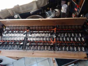
Now the cell modules have been removed from their original home, it’s time to get them repurposed! A custom mounting board has been constructed from timber, and the modules mounted on them. To say this assembly is heavy would be an understatement – it’s barely a two-man lift!
As assembled in the car, the pack as 96S1P, with every cell in series. As we need a low voltage bus, the modules have been reconfigured for 4S4P, in total this makes 4S24P with all 6 modules bussed together. As the cell interconnects are laser welded, some ingenuity was required here.
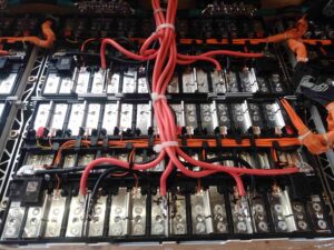
It turned out the best method (and the safest, to avoid any swarf shorting out cells!), was to use a grinder to cut off the top of the loop on the aluminium interconnects, separating them.

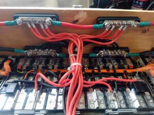
12 5-way bus bars have been installed on the board, and 25mm² cable links them together. To get the angry pixies from the cell modules, 8mm² flexible silicone cable has been used, 4 links to a bus bar. This setup should provide more than enough current capacity.

Here can be seen the cell interconnects – and the grinder cuts to separate them where required to break the module up into 4S strings. As the interconnects are Aluminium, special solder was required to get the copper cables soldered down, in my case I used Alusol 45D solder, which contains a very active flux capable of stripping the oxide from the Aluminium.

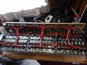
Finally, here is the new pack, all connected together. All that needs to be done now is the balance wiring loom, which will allow the BMS to sense each cell voltage individually, and connection of the BMS, Coloumeter & fuses, this will all be covered in a future post!
