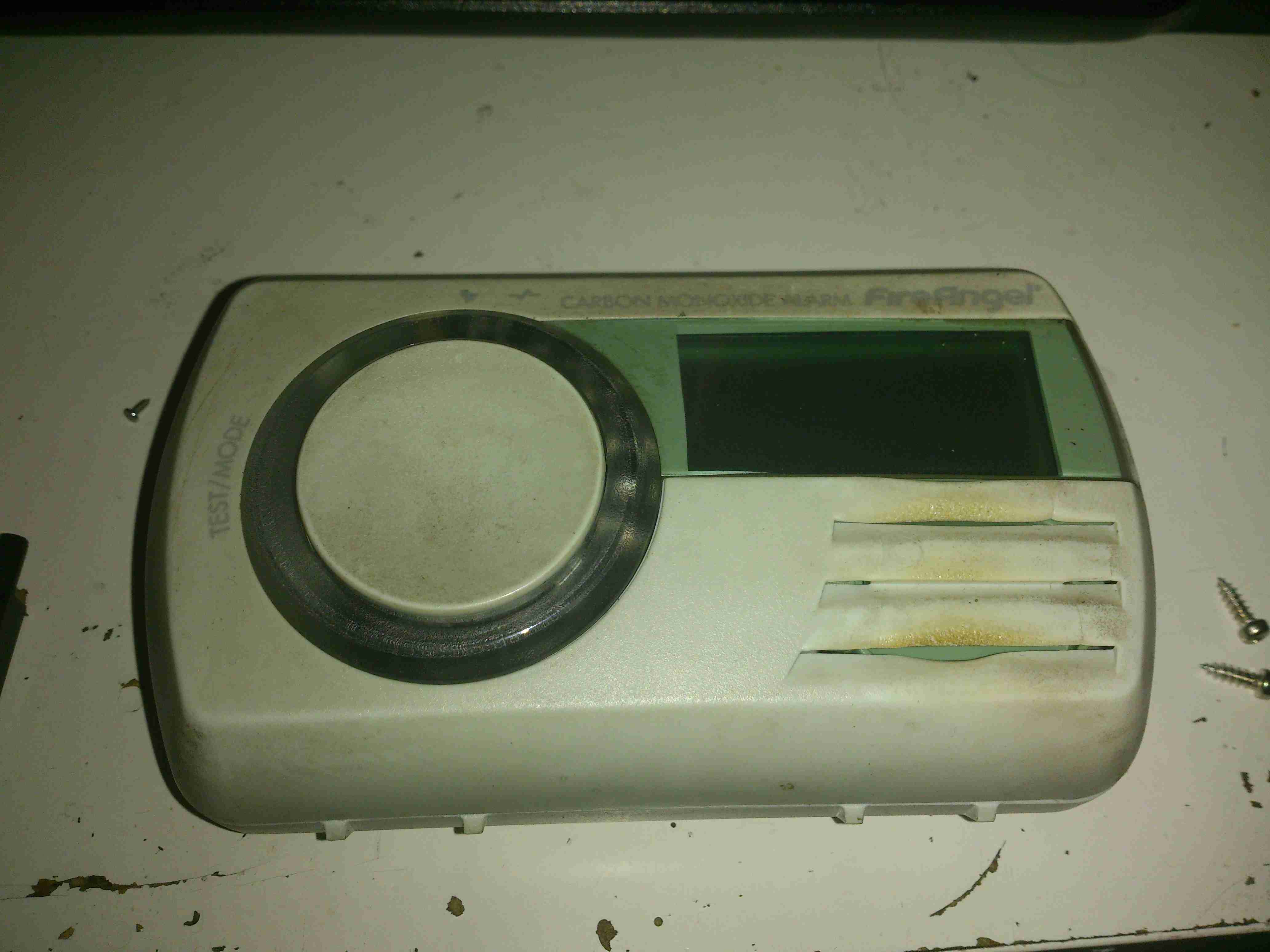
This detector has now been retired from service since it’s a fair bit out of date. So here’s the teardown!
Unlike older detectors, this unit has a built in battery that never needs replacing during the life of the sensor, so once the unit reaches it’s expiry date it’s just trashed as a whole.
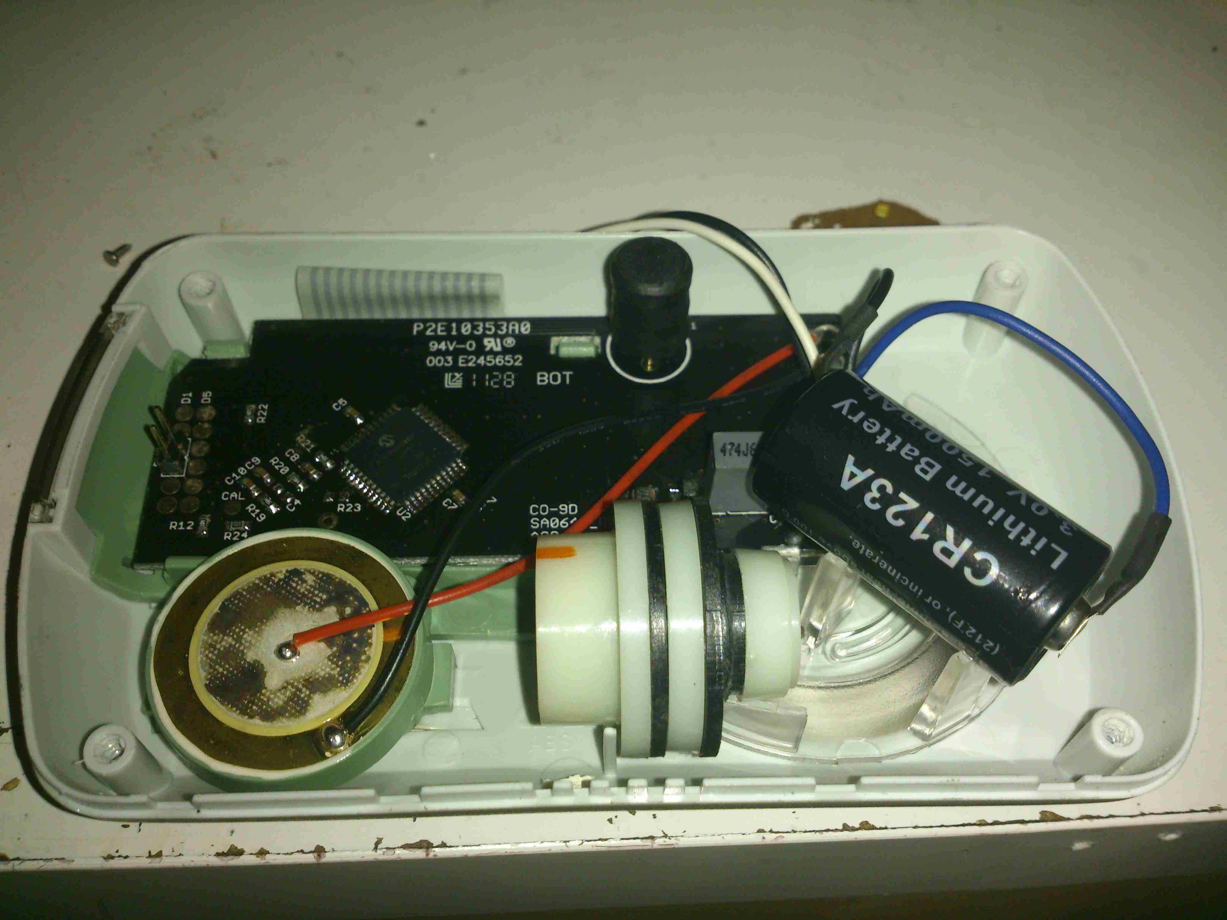
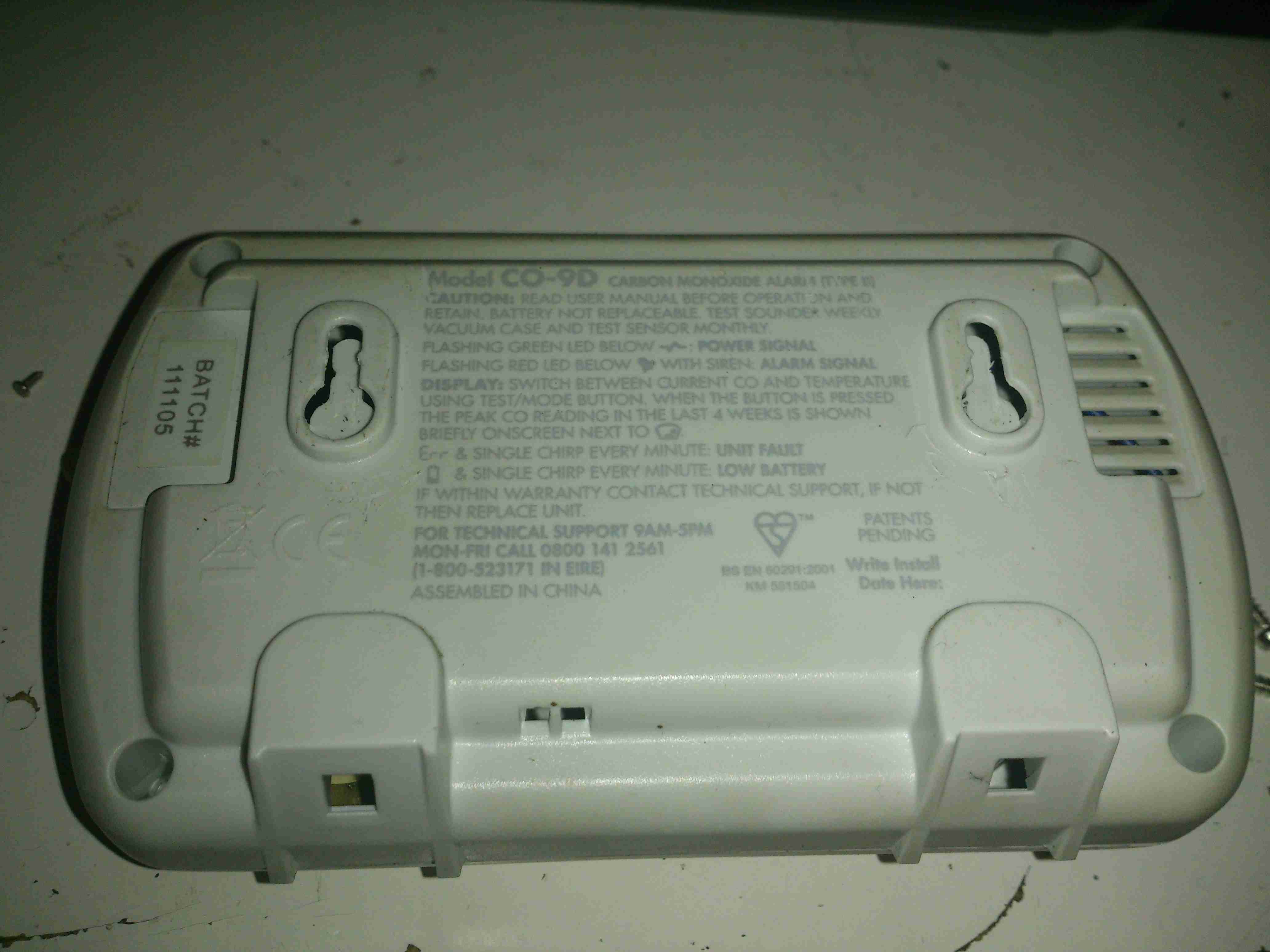
4 screws hold the cover on, here’s the internals of the detector. There’s a 3v CR123A LiMnO² cell at the right for power, rated at 1500mAh. A 7 year life is quite remarkable on a single cell!
The sensor is just to the left of the lithium cell, and is of quite unusual construction. Previous CO sensor cells I’ve seen have been small cylinders with a pair of brass pins. This one appears to use a conductive plastic as the connections. These sensors contain H²SO⁴ so they’re a bit hazardous to open.
There are no manufacturer markings on the sensor & I’ve not been able to find any similarly shaped devices, so I’m unsure of it’s specifications.
The alarm sounder is on the left, the usual Piezo disc with a resonator to increase the loudness.
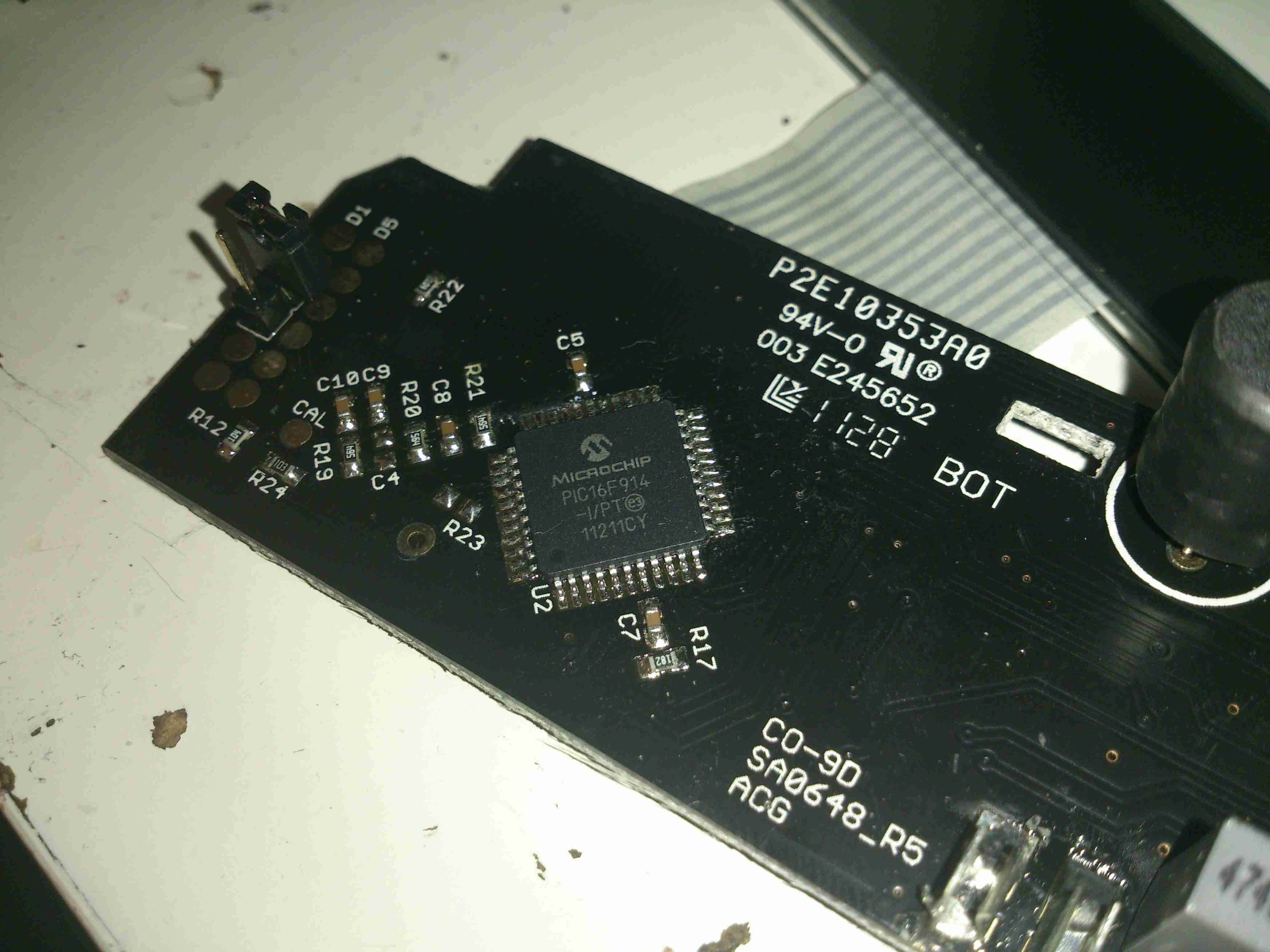
The brains of the device are provided by a Microchip PIC16F914 microcontroller. This is a fairly advanced device, with many onboard features, and NanoWatt™ technology, standby power consumption is <100nA according to Microchip’s Datasheet. This would explain the incredible battery life.
The choke just at the right edge of the photo is actually a transformer to drive the Piezo sounder at high voltage.
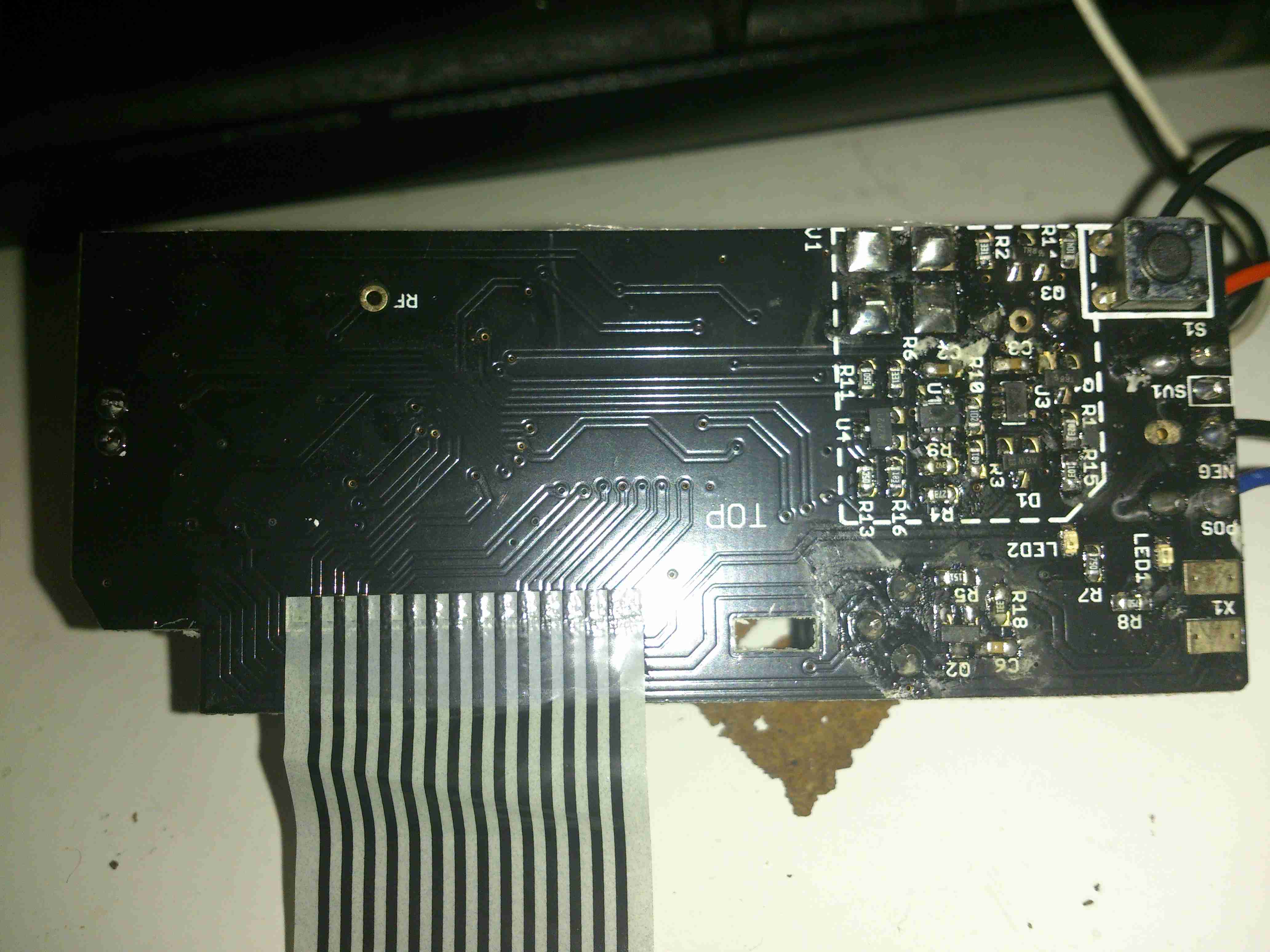
Here’s the PCB with the LCD frame removed. Not much to see on the this side, the silence/test button top right & the front end for the sensor.
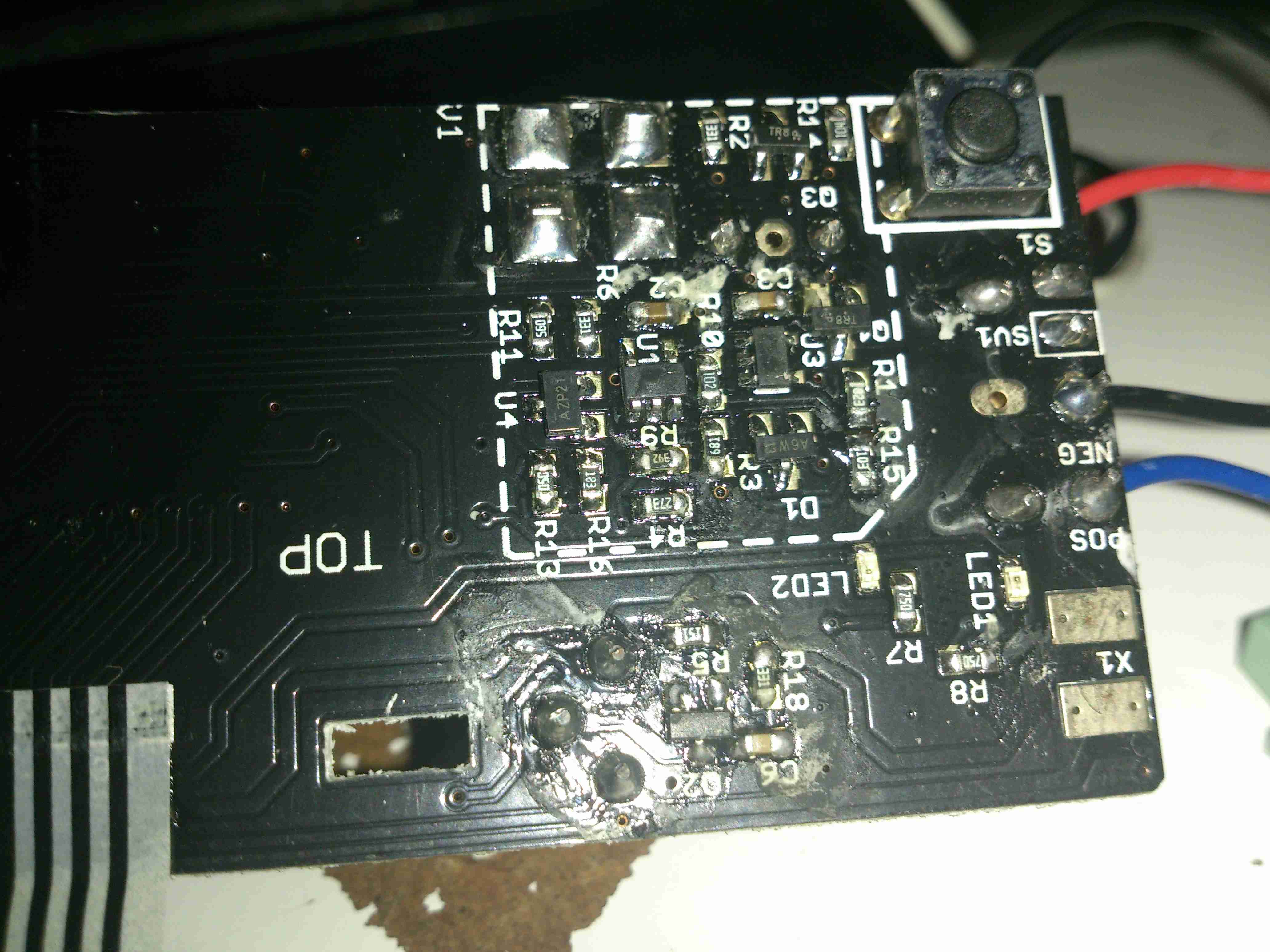
Here’s a closer look at the front end for the CO sensor cell itself. I haven’t been able to decode the SMT markings on the SOT packages, but I’m guessing that there’s a pair of OpAmps & a voltage reference.

You could solder in a new c123a battery
I’ve done the exercise. Problem after , although testing correct on the famous incense test, the temperature reading is 4 degrees to high.
Most of these type of instruments are not very reliable.
Hi Robin,
The battery life in these units is designed to last as long as the chemical life of the CO sensor itself, so replacing it isn’t something I’d do. I’m not sure what they’re doing to sense temperature, but they may be using an onboard sensor in the PIC itself. This would explain the 4°C temperature error. As you say though, they’re not very reliable!
Owned many of these, fine little devices, although they should be designed to be serviceable with replacement batteries and sensors, if they can’t be made to work for >7/10 yrs.
Now , if you have a spare detector and want to turn it off to extend its life, is this safe?
Insert the original power on clip back into the rear socket (or an opened paper clip) and jiggle until the screen goes and stays blank.
Is it OK to assume “no power = no degradation of life of the detector head”?
BTW, a poss. easier alternative is the little (anti-tamper?) header socket located in the plastic hatch that’s labeled “BATCH XXXXXX” which can be cut out of its ‘cage’ and reinserted across the two header pins. Removing it also blanks the screen, altho’ I’ve not established if it’s due to cutting the power or if blanking is done via a digital input.