Here goes the local unlicensed prat yet again on GB3MR. I was trying to have a QSO with another station on there, but due to his weak signal, and the pirate’s strong signal, it made it impossible. Here’s the audio 🙂
Here goes the local unlicensed prat yet again on GB3MR. I was trying to have a QSO with another station on there, but due to his weak signal, and the pirate’s strong signal, it made it impossible. Here’s the audio 🙂
I often find myself carrying by go bag up to the boat during trips, so I can do some radio. However at 16lbs it’s a pain on public transport. A fixed radio was required! Another Wouxun GK-UV950P was ordered, and the fact that the head unit is detachable from this radio makes a clean install much easier.
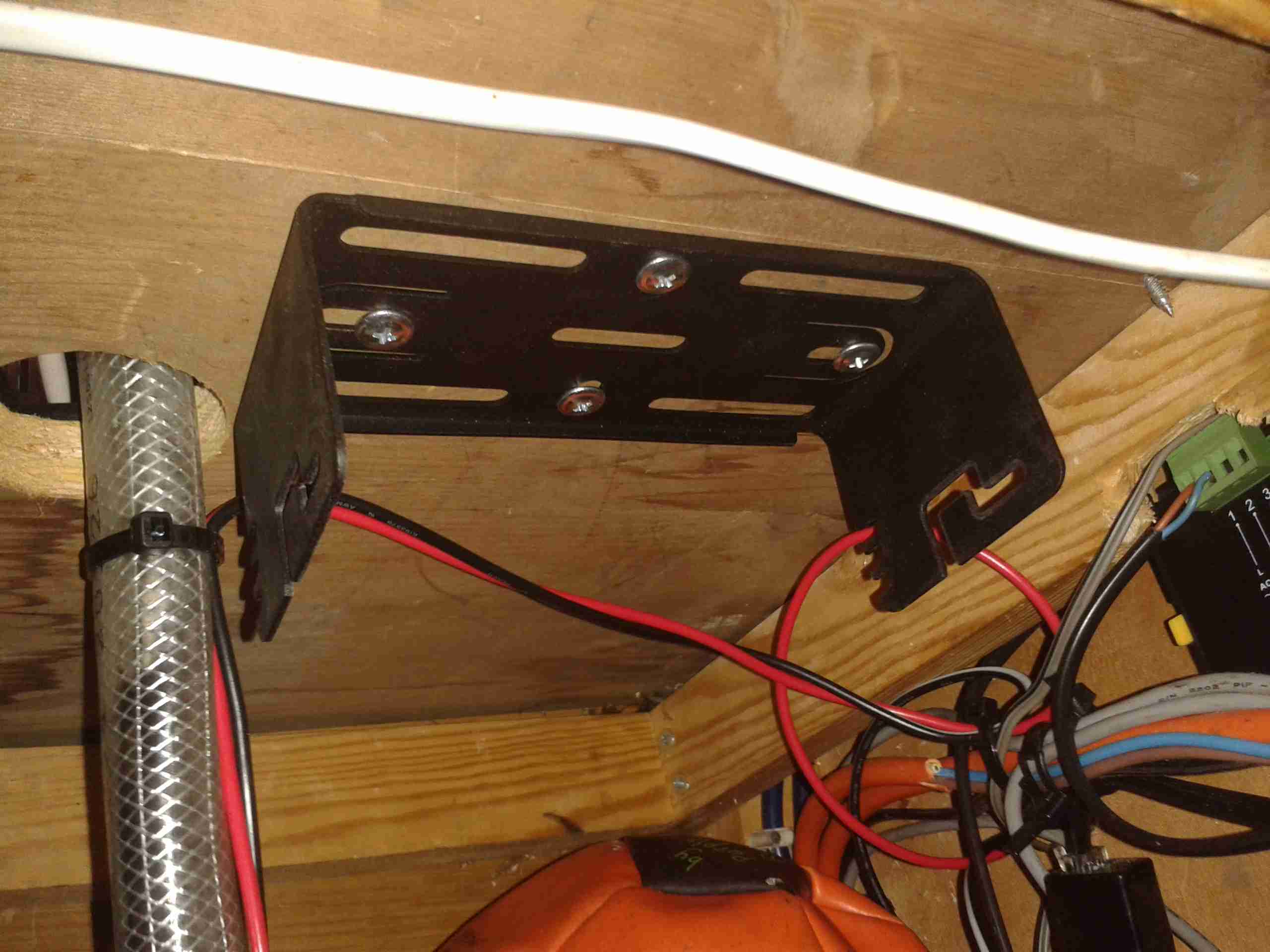
I found a nice spot under a shelf for the main radio unit, above is the mounting bracket installed.
This location is pretty much directly behind where the head unit is placed, but the audio is a bit muffled by the wooden frame of the boat & some external speakers will be required for the future.
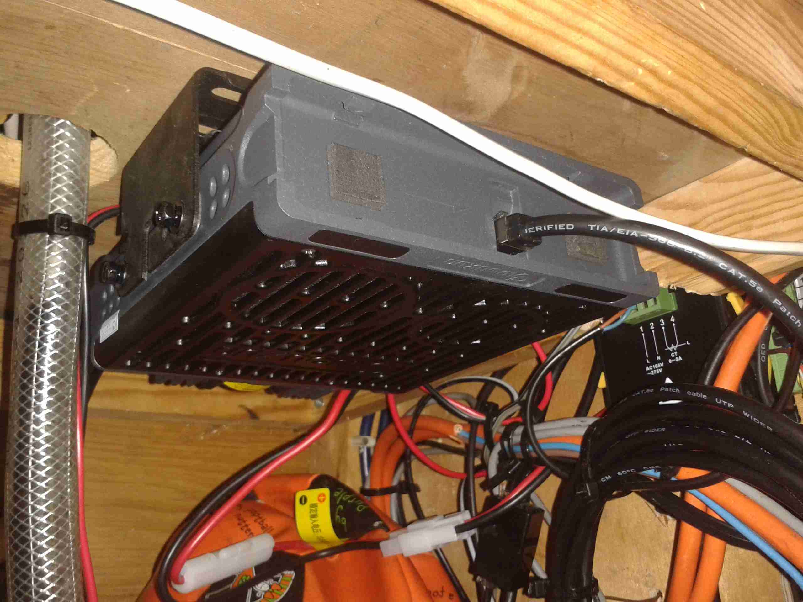
Here’s the main radio unit mounted on it’s bracket, with the speakers facing down to improve the audio slightly. I used the supplied interface cable for the head unit, even though it’s too long. I do have the tools to swage on new RJ-45s, but the stuff is a pain to terminate nicely & I really just couldn’t be bothered. So it’s just coiled up with some ties to keep it tidy. Main power is provided directly from the main DC bus. (880Ah total battery capacity, plus 90A engine alternator, 40A solar capacity).
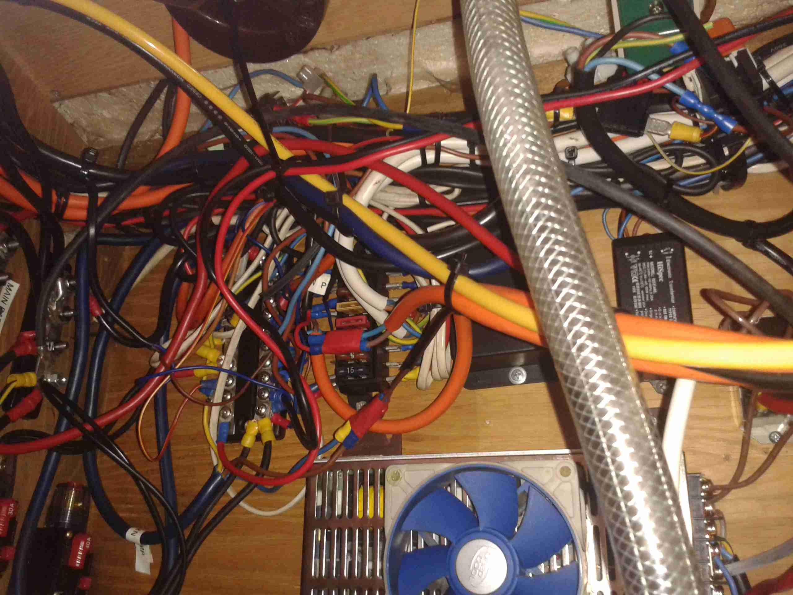
Here’s the main DC bus, with the distribution bars. With the addition of new circuits over the years, this has become a little messy. At some point some labelling would be a good idea!
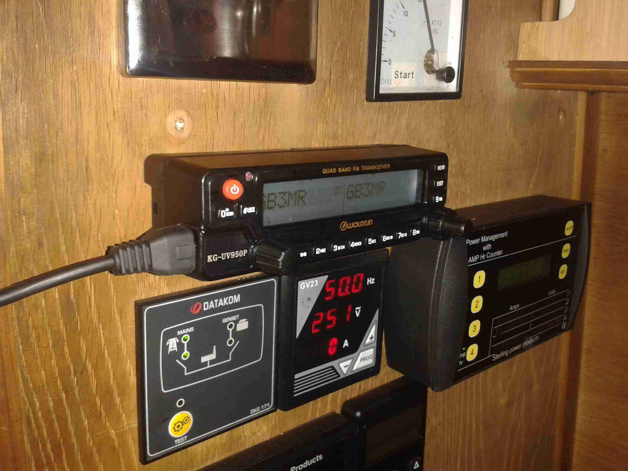
Finally, the head unit is installed in a spot on the main panel. It does stick out a little more than I’d like, but it’s a lot of very dusty work with the router to make a nice hole to sink it further in. All my local repeaters & 2m/70cm simplex are programmed in at the moment.
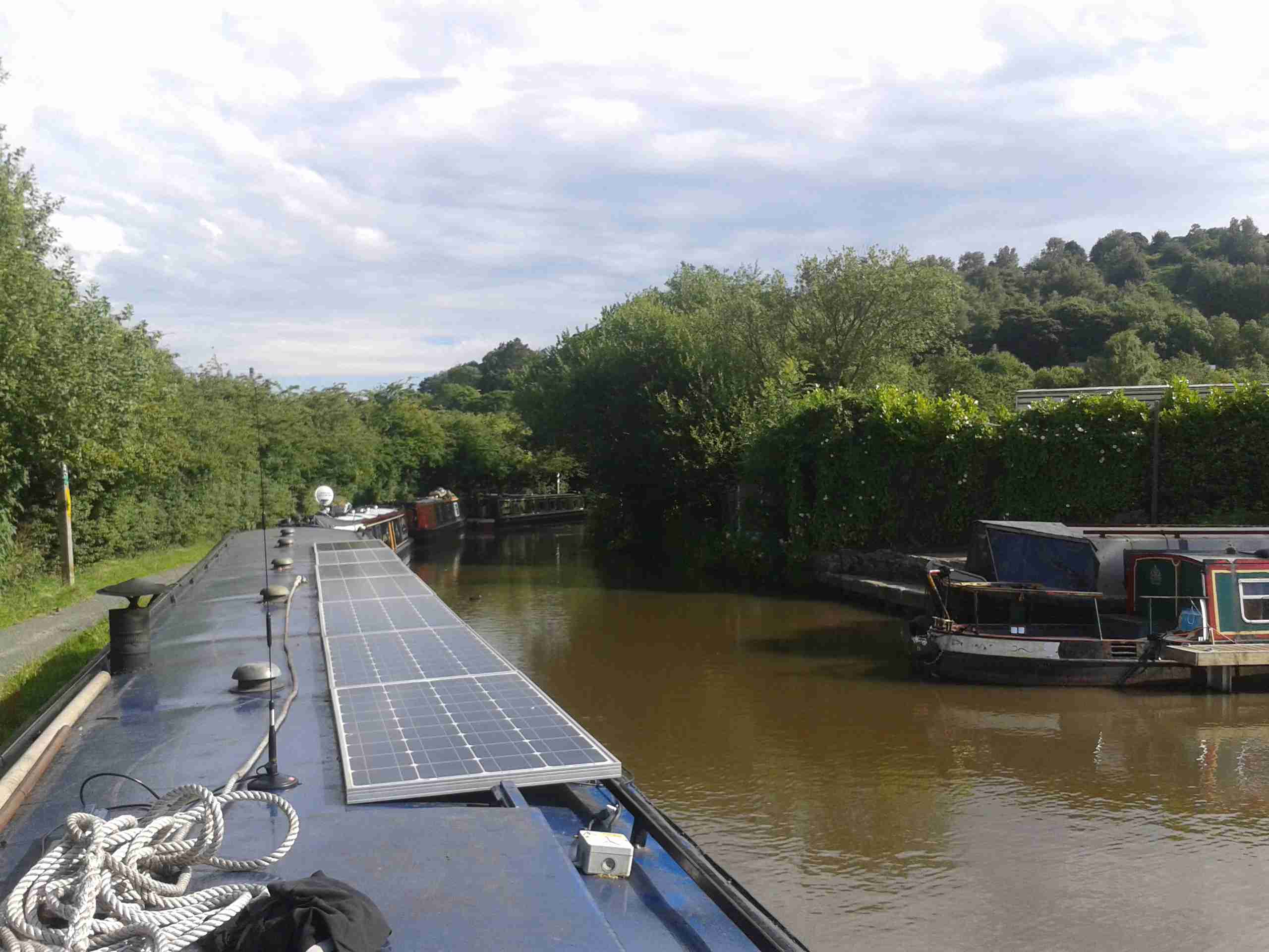
I’ve got a Nagoya SP-80 antenna on a magmount for the radio, a magmount being used due to the many low bridges & trees on the canal. (It’s on the roof next to the first solar panel above). I prefer it to just fall over instead of having the antenna bend if anything hits it!
Part 2 will be coming soon with details of the permanent antenna feeder.
73s for now!
Here we go again with the GB3MR local idiot. He does always try to get a response from people, but we seem to be able to filter out this crap. 🙂 Here’s the audio for your listening pleasure. 🙂
With every piece of Chinese electronics I obtain, mainly Baofeng radios, they come with a Europlug-type power adaptor, and a universal plug adaptor for the mains.
The charger units aren’t too bad, there’s a fair amount of isolation between the primary & secondary, and even though they’re very simple & cheap, I can’t see any immediate safety problems with them.
The plug adaptors, however, are a different matter. These things are utterly lethal!
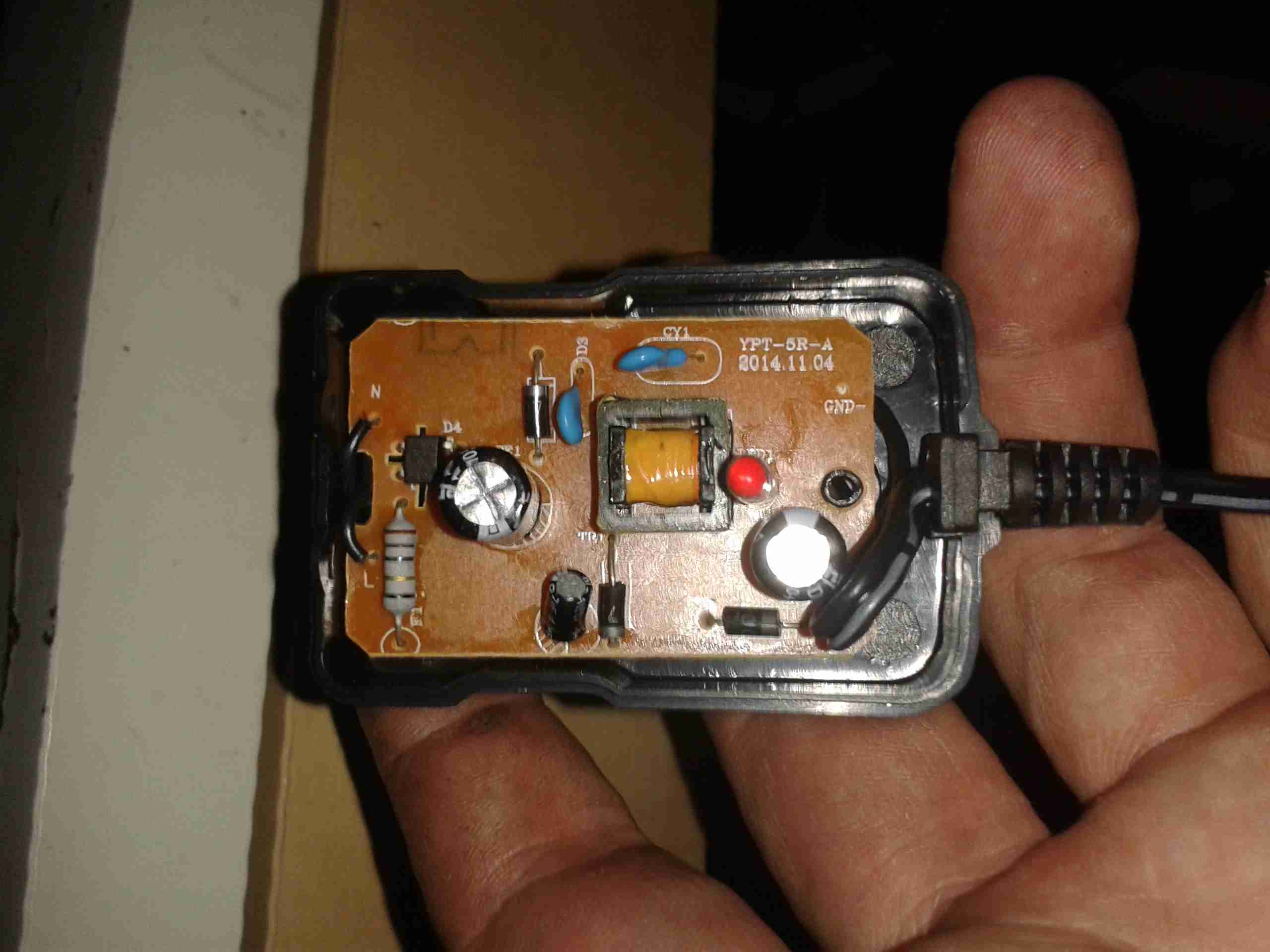
Here’s the inside of the PSU. It’s just a very simple SMPS, giving an output of 10v 500mA. The fuse is actually a fusible resistor.
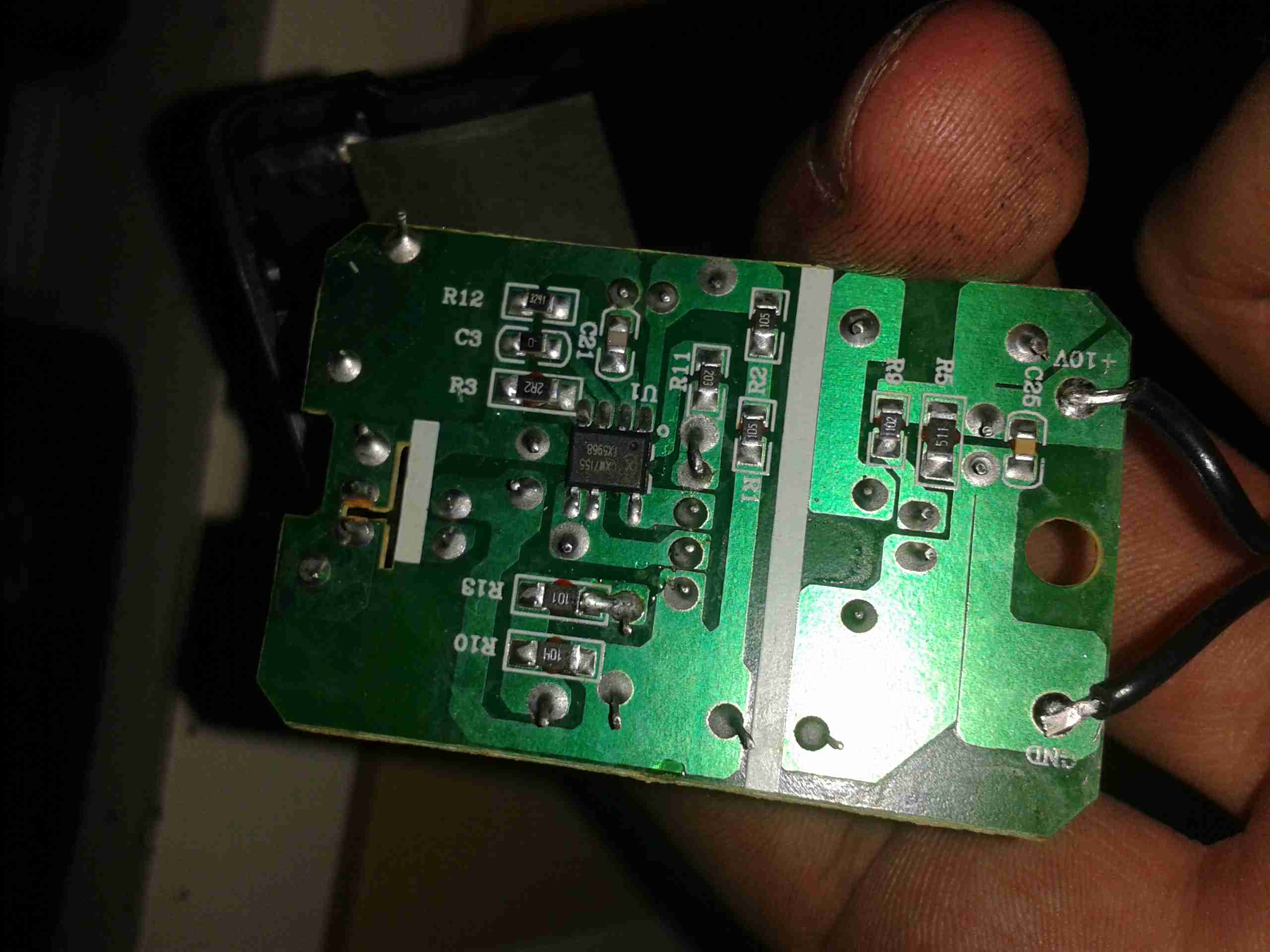
Here’s the back of the PCB with the SMPS control IC. I can’t find any English datasheets for this part unfortunately.
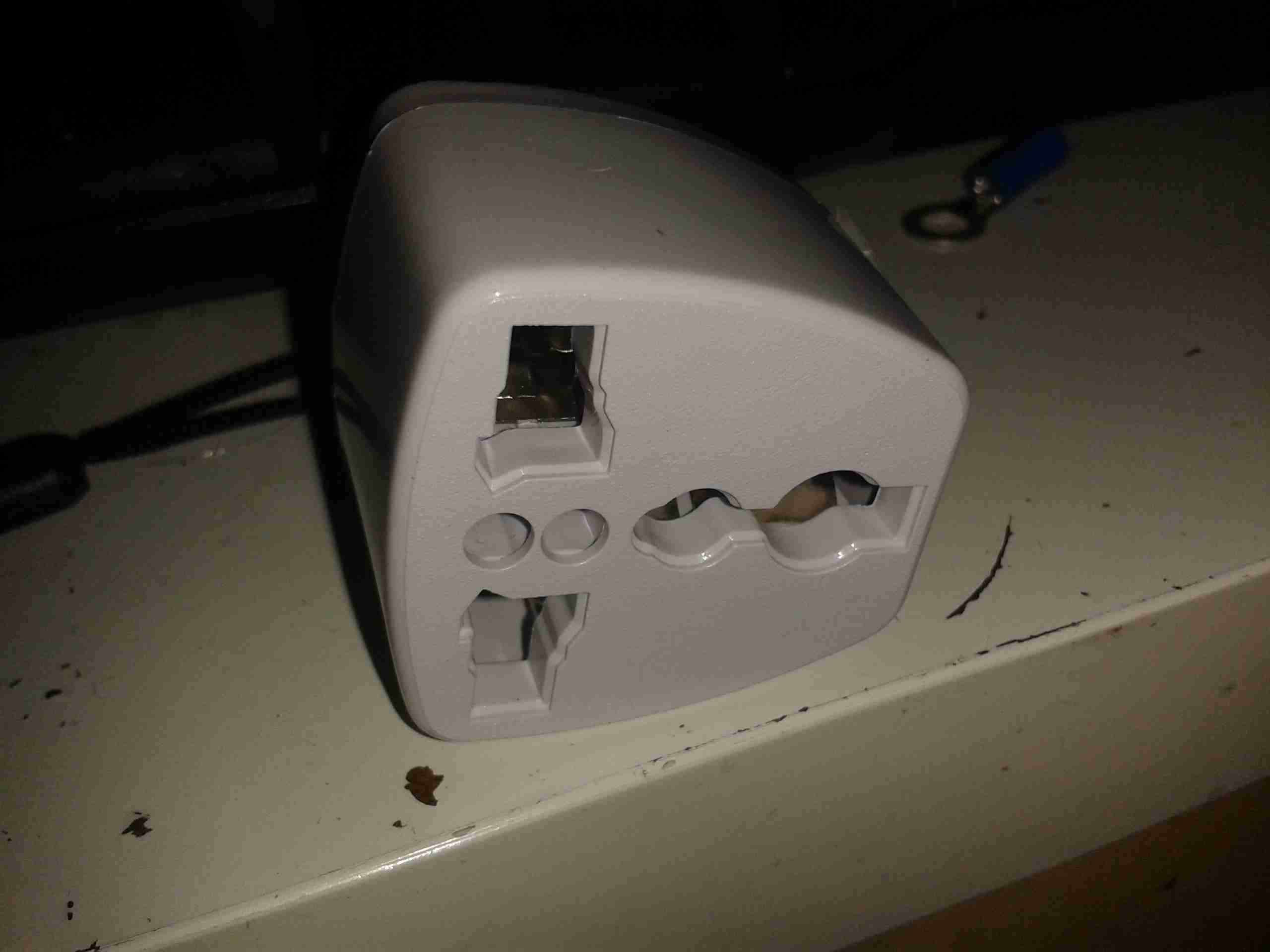
Here’s the dangerous adaptor. There’s no safety shield, so the live parts are exposed.
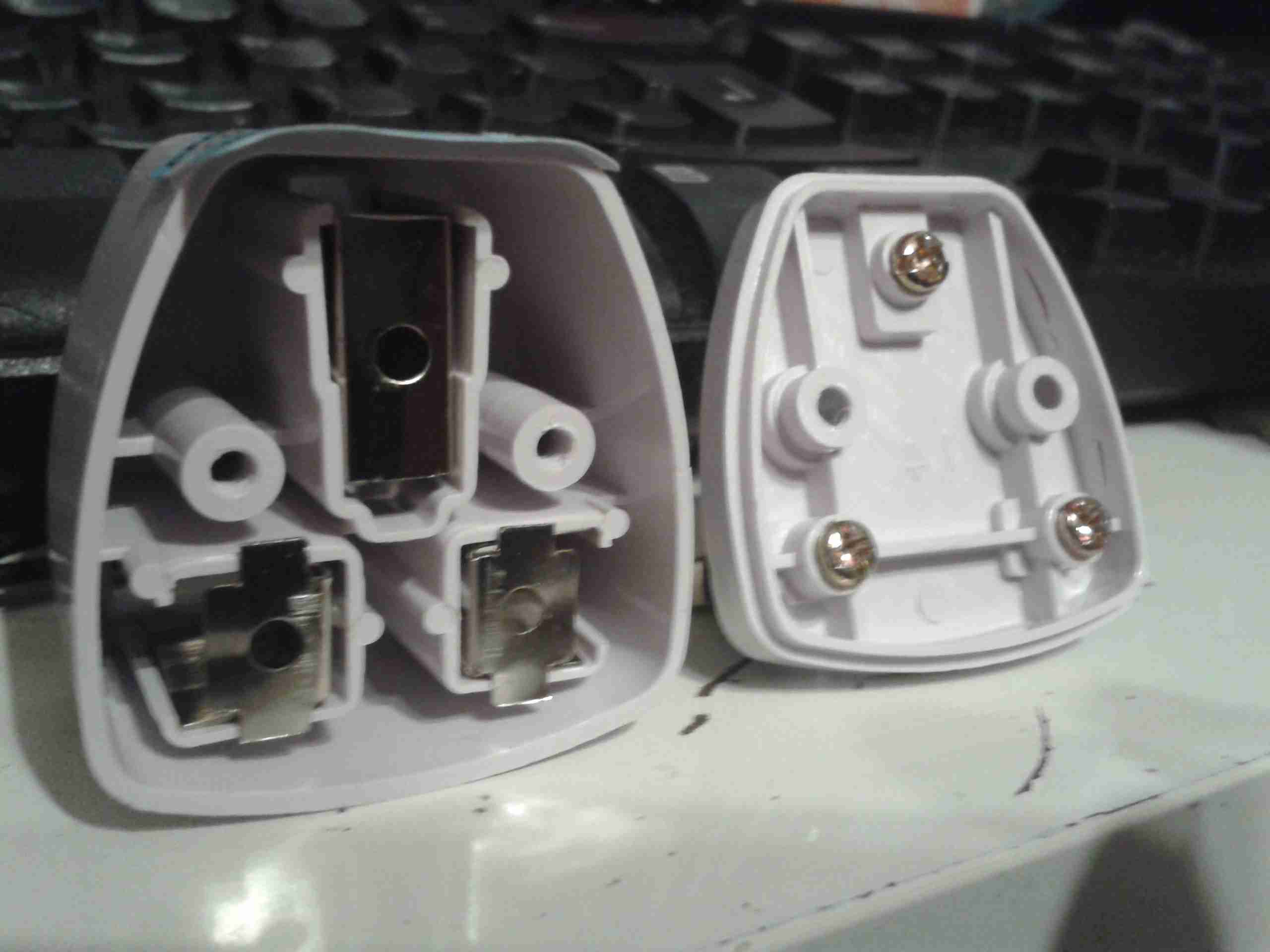
Here’s the adaptor split apart. The output contacts are on the left, and rely just on pressure to make contact with the brass screws on the mains input pins to provide power.
This is a very poor way to get a connection, a dirty or worn contact here would create a lot of heat if any significant power is pulled through, and could quite possibly result in a fire.
Not surprisingly, I bin these things as soon as I open the box, and charge all my radios with a 12v charging system.
Thanks to Lewis over at Distant Signal Radio, the bad influence he is on my bank balance ;), I’m the proud new owner of a new Baofeng. This time it’s the UV-82.
This radio is a little different from the other Baofengs I have. Here are the main differences:
This radio has a different method of selecting the VFO mode – holding the menu key while the unit is powered on. This is a little awkward, but since I only usually use my local repeaters when I’m mobile, it’s not much of an issue.
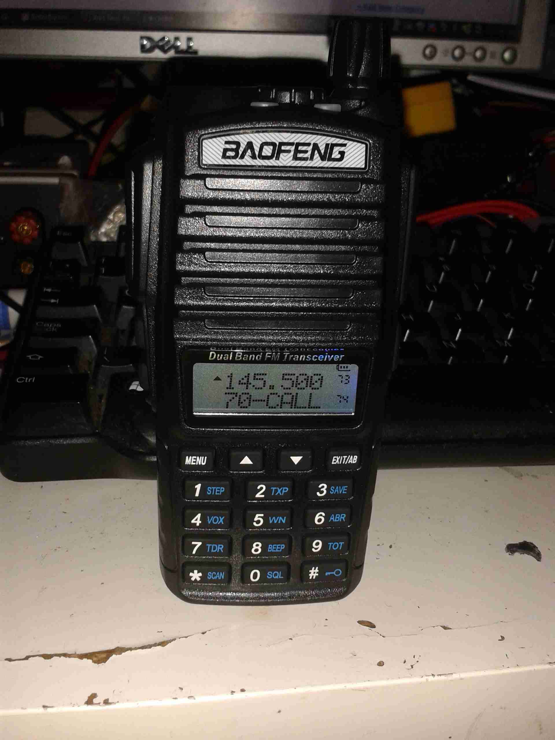
Here’s the radio itself, it has a much more commercial feel to it than the UV-5Rs, and it’s slightly bigger. Mainly due to the use of a larger standard battery & larger loudspeaker.
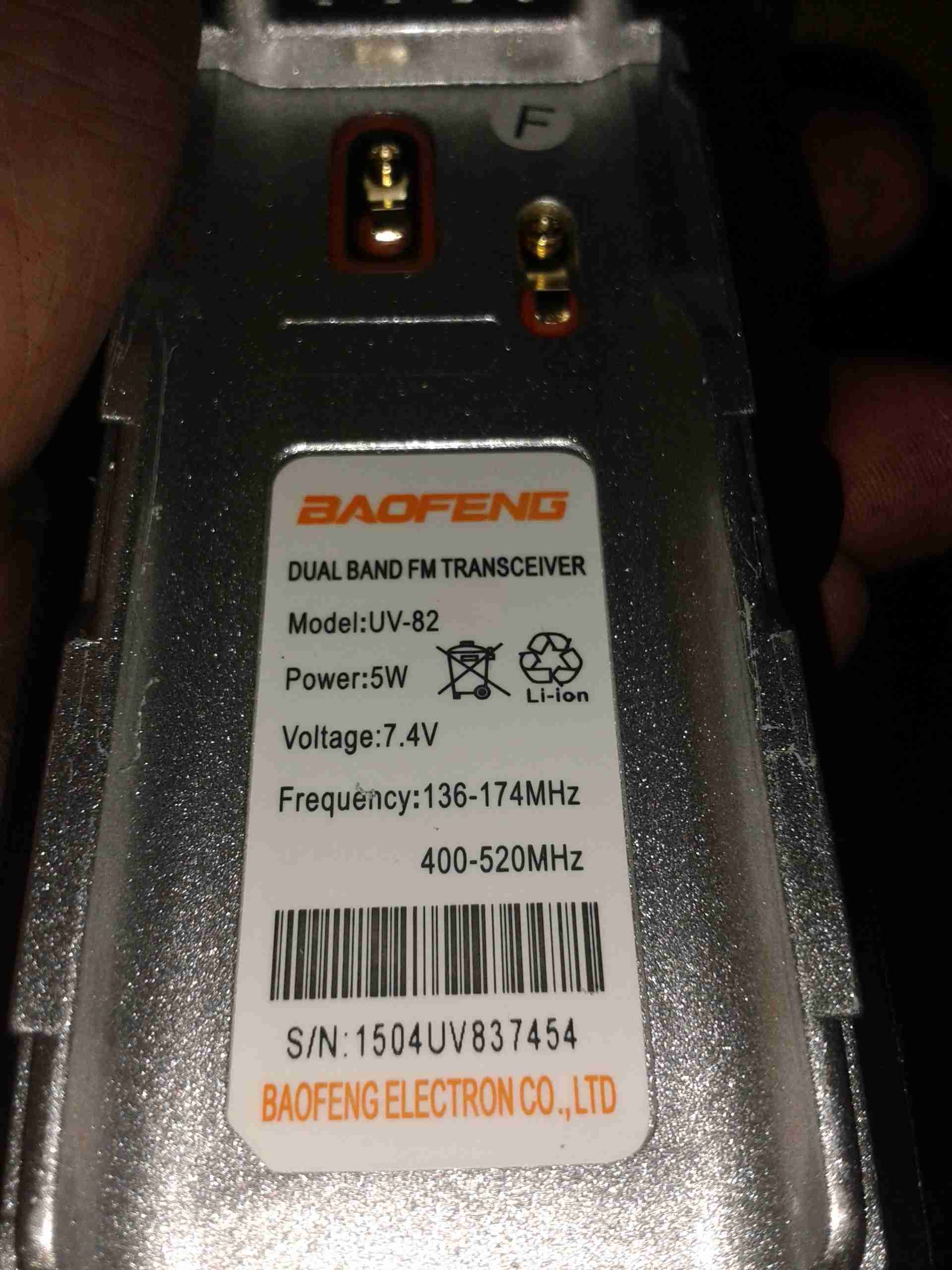
Back of the unit with the spec label. As per usual Baofeng are a bit conservative with the power ratings, more to come on that below.
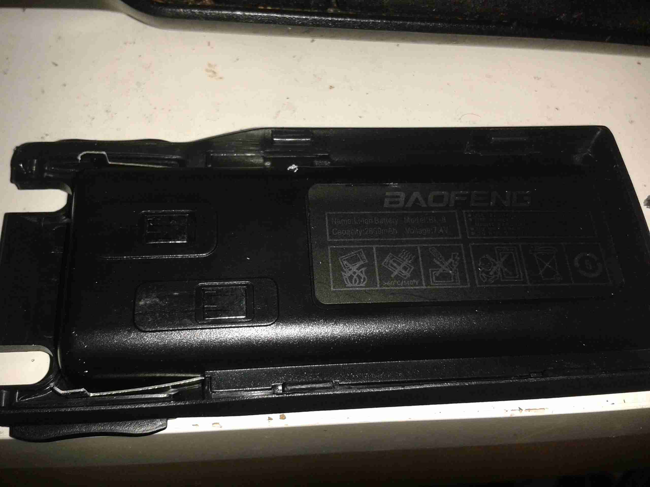
Here’s the battery pack, a 2-cell lithium-polymer unit. This has a bigger capacity than the standard UV-5R battery, at 2800mAh.
Here are the power settings as measured by my GY-561. Frequencies used are 145.500 & 433.500
VHF High: 7W
VHF Low: 2.5W
UHF High: 6W
UHF Low: 3.1W
Here we go again on GB3MR tonight, the guy jumped in after I finished a QSO (which was mainly centred on the Marine VHF band & busy channels).
He’s then going on about legality, but he’s clearly so pissed that I can’t actually get full sentences out of it. Here it is for your listening pleasure.
Came across this today while scanning through frequencies. Not sure of their exact QTH, but there’s references to the Oldham area in Manchester, about as far away as you can get from any marine or commercial shipping area in the county. I didn’t hear any marine callsigns or vessel names either so I’m guessing that they’re using the frequency illegally.
UPDATE!
I’ve been reliably informed that there is a frequency overlap between the marine band Channel 83 & a local comms repeater here in Stockport.I find the fact that Ofcom have allowed a frequency overlap here a little odd, since the marine band is used on the inland waterways, although not as much as coastal marine locations.
Yet again here’s our friend “Tommy” on GB3MR, operating unlicensed.
Unfortunately the manual for the eBay GY561 Frequency & RF Power Meter is very badly translated, but I think I have figured out the calibration procedure, so here it goes 🙂
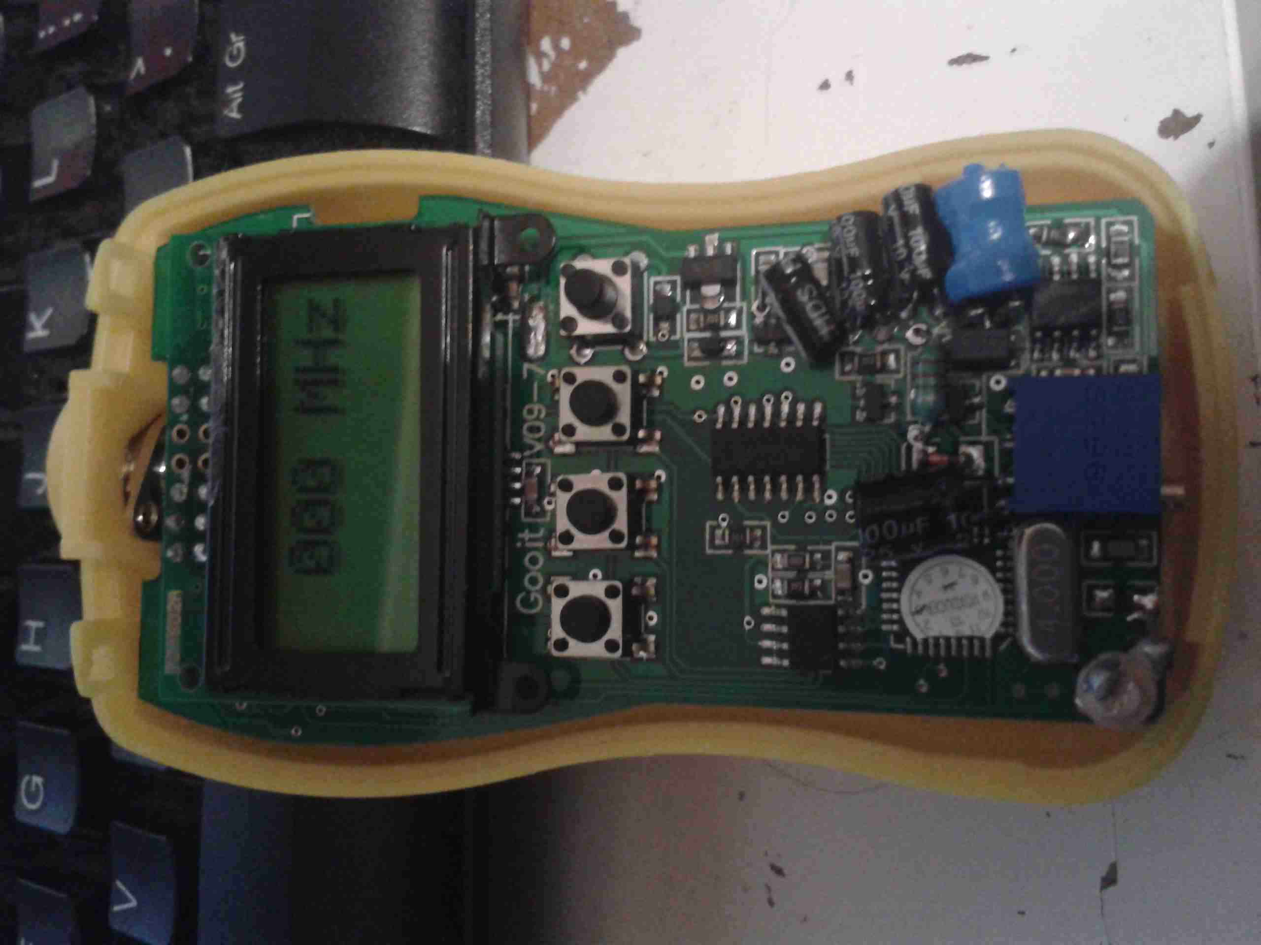
On removing the front cover, which is just clipped on, there are 4 buttons. The only button that is usually available is the one on the far right, the power button.
I will term these buttons A, B, C, D, starting from the left side.
To get into the initial calibration screen, in the above image, hold button A while the power button (D) is pressed. Release the power button (D), then release button A.
The meter will show the screen above, where the frequency to calibrate can be chosen. This goes in 5MHz steps, 0-500MHz, using the B button to go down in frequency, and the C button to go up.
Once you’ve selected the frequency you wish to calibrate against, press button A, and the following screen will appear:
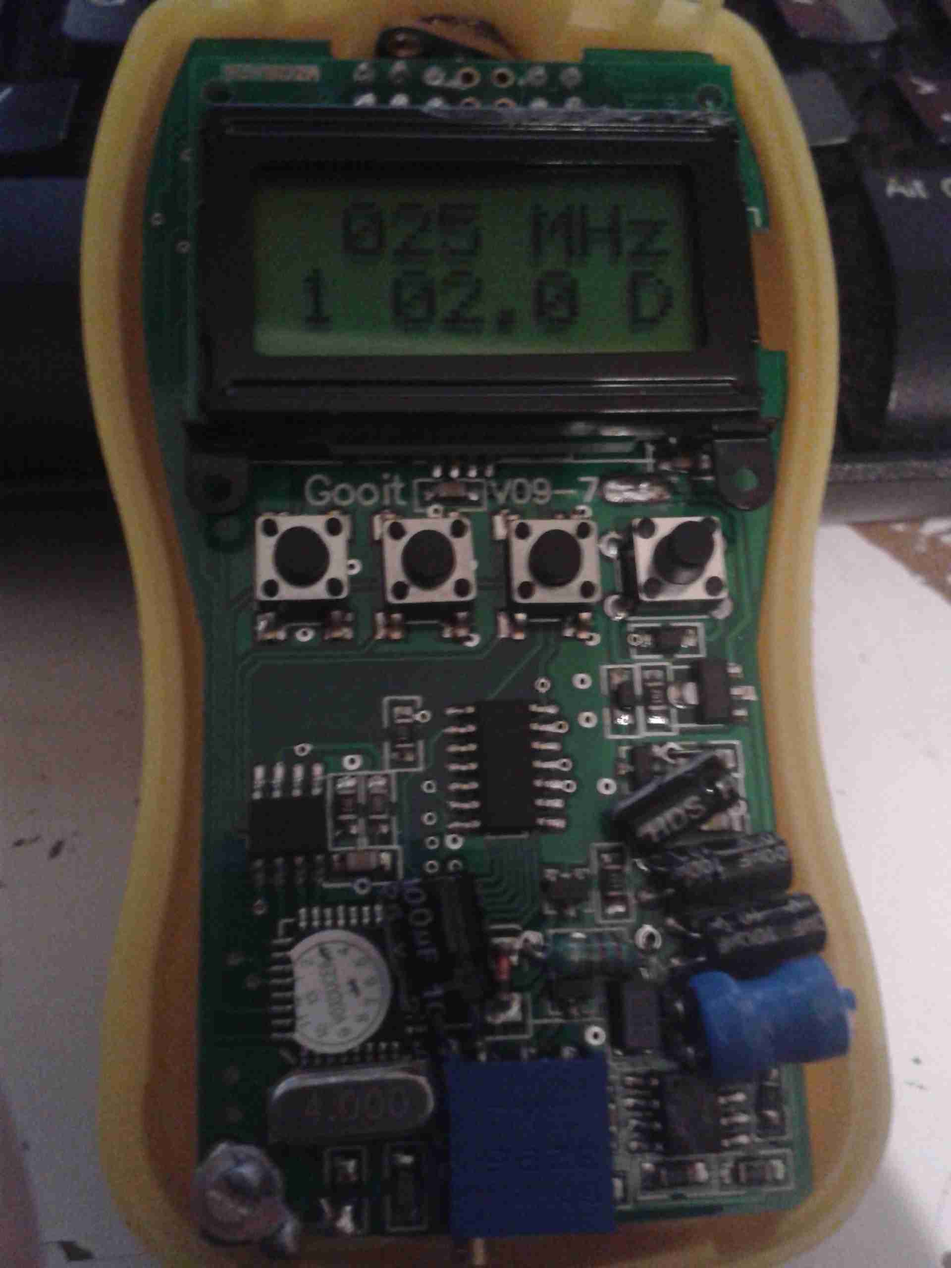
On this screen, the actual calibration can be done.
The number in the bottom left signifies the power level setting, from 1-5. The centre number is the calibration setting in Watts. The D in the bottom corner signifies that the setting is at the factory default.
Button C will cycle through the power level settings, for 2W, 5W, 10W 20W, 40W. This allows calibration at different power levels per frequency.
Once you have the frequency to calibrate, and you’ve selected the power level to calibrate at, connect a known RF power source to the input of the unit.
At this point, key the transmitter, and press button A. The display will change to the following:
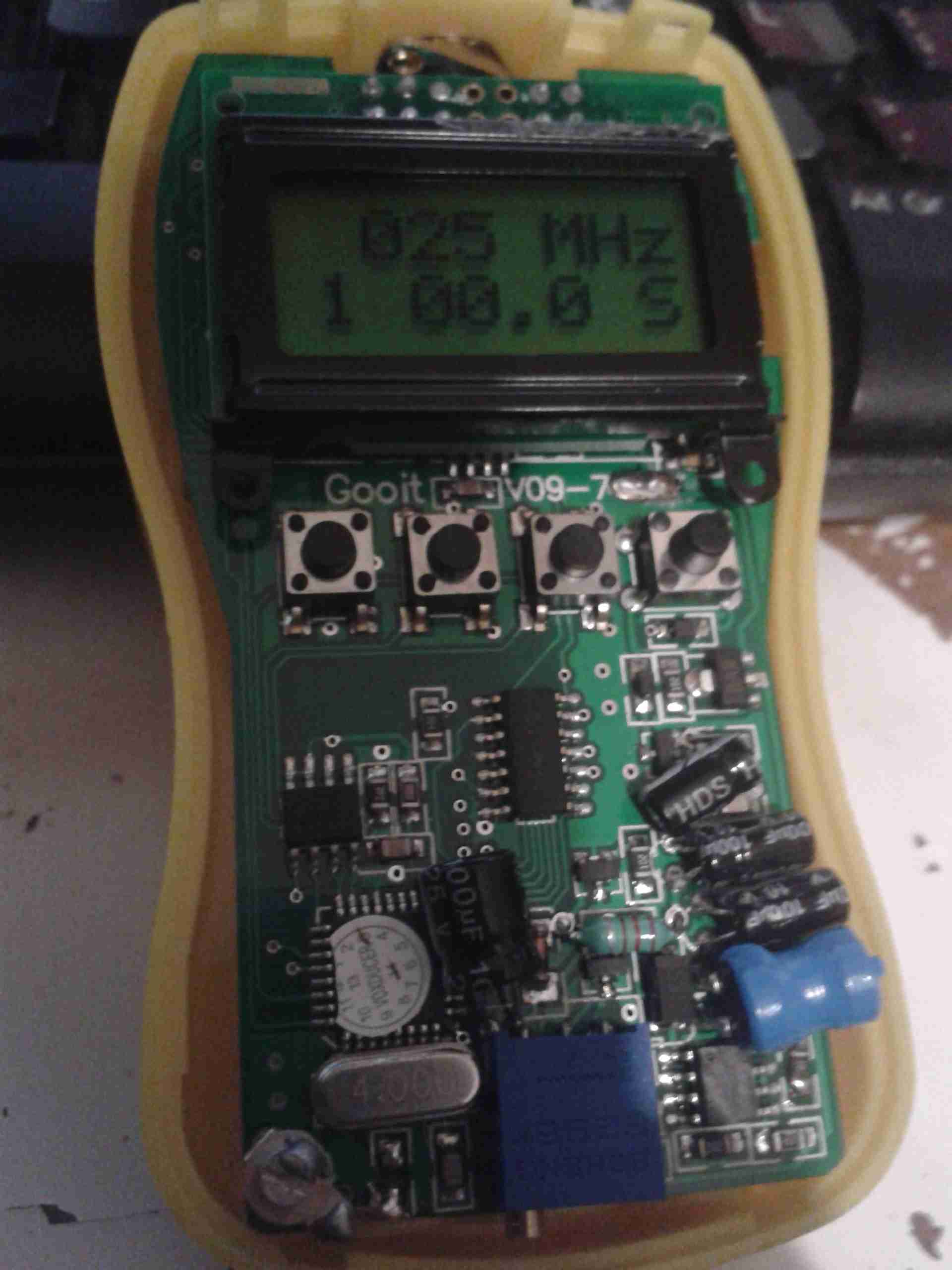
When on this screen, you can set the power level of your RF source. Use the A key for +0.1W, the B key for +1W, and the C key for +10W.
Once you’ve keyed in the power of your source, press button D to save the setting. The “S” in the bottom corner will change to a “C”, to indicate a user calibration has been entered:
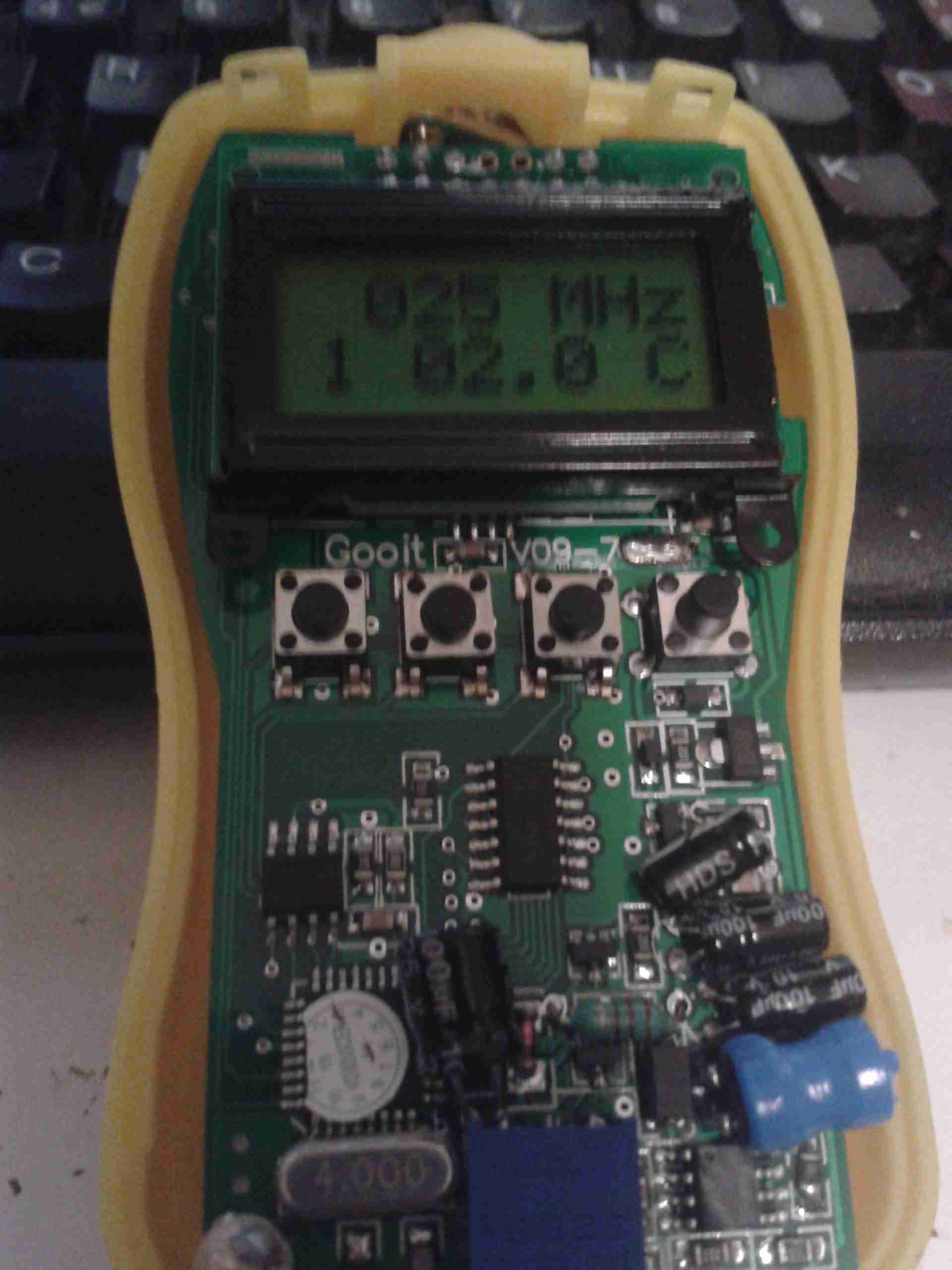
If you make a mistake with entering the power level, press the “C” key to cycle up to 60W, once at this level, another press of the button will reset the reading to zero. You can then enter the power level again.
If you wish to revert a user-entered setting to the factory default, press button B on the page above. The “D” will reappear in the bottom corner to indicate the setting has been restored.
At this point you can either press button C to calibrate at another power level for this frequency, or press button D to go back to the frequency selection.
Press button D again when at the frequency selection page to turn the unit off. The unit will then power up normally next time the power button (D) is pressed.
Here’s the final instalment of the new high gain TV antenna & it’s masthead amplifier.
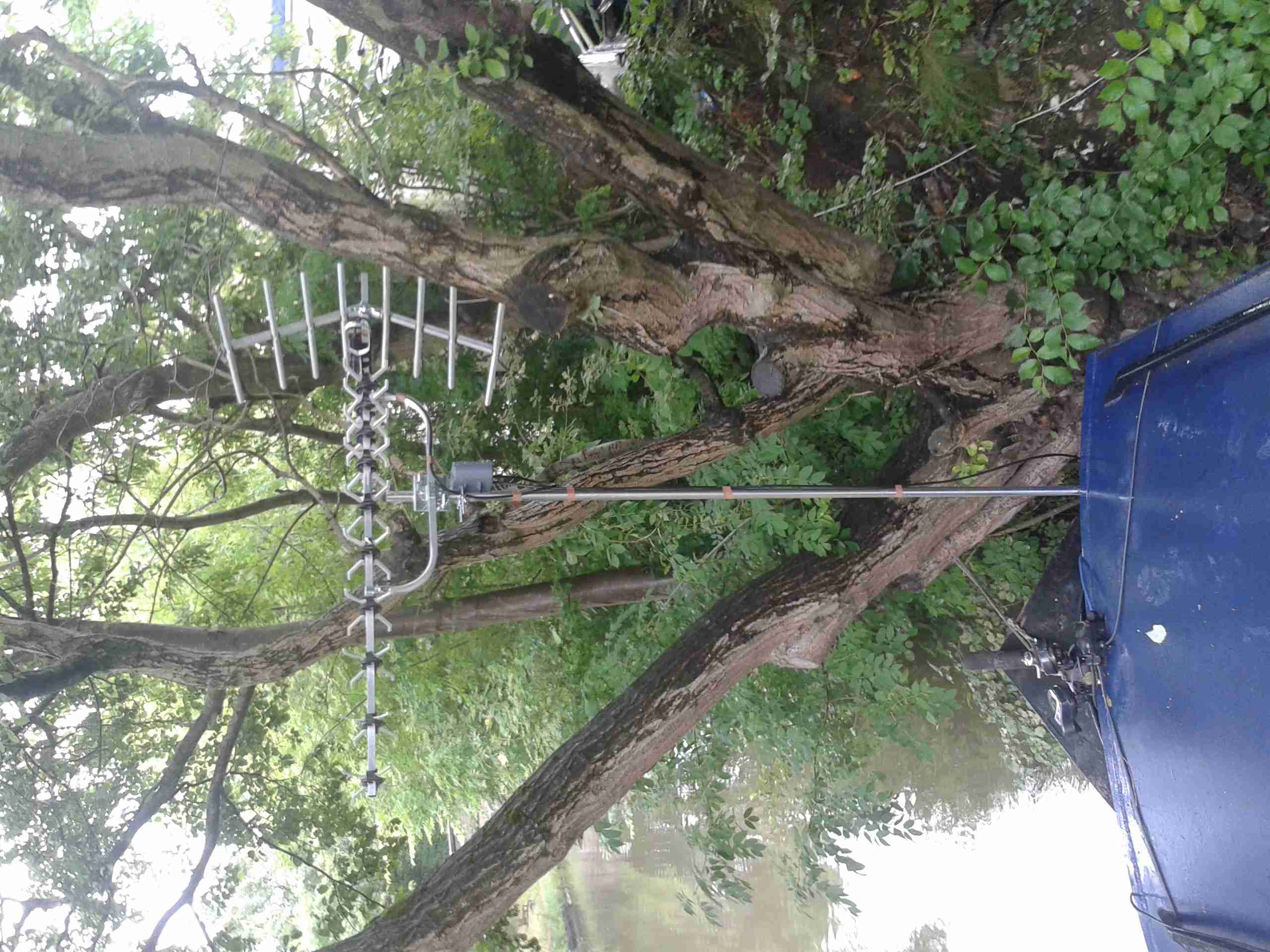
Here’s the new antenna on it’s removable mast. This apparently will give 13db of gain over the old antenna. The masthead amplifier box is mounted just below.
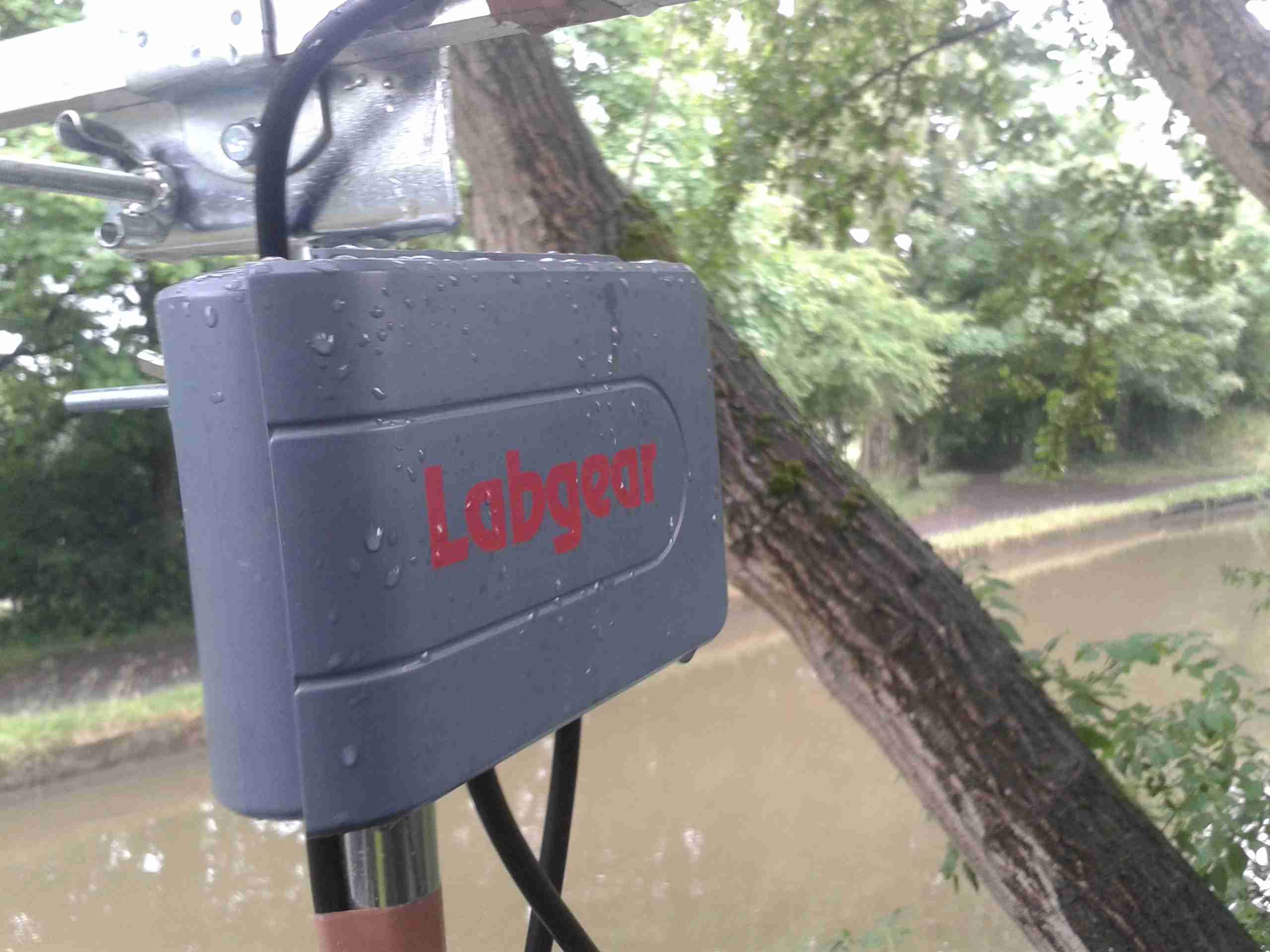
Here’s the amplifier just below the antenna. I do hope the seals on this hold against the weather! The amplifier inside isn’t protected at all.

Here’s the module itself. This is powered by +12v injected into the coax with the power supply I previously modified. F-type connectors are used. (I don’t like these connector types, their lack of a true centre pin is poor design in my opinion).
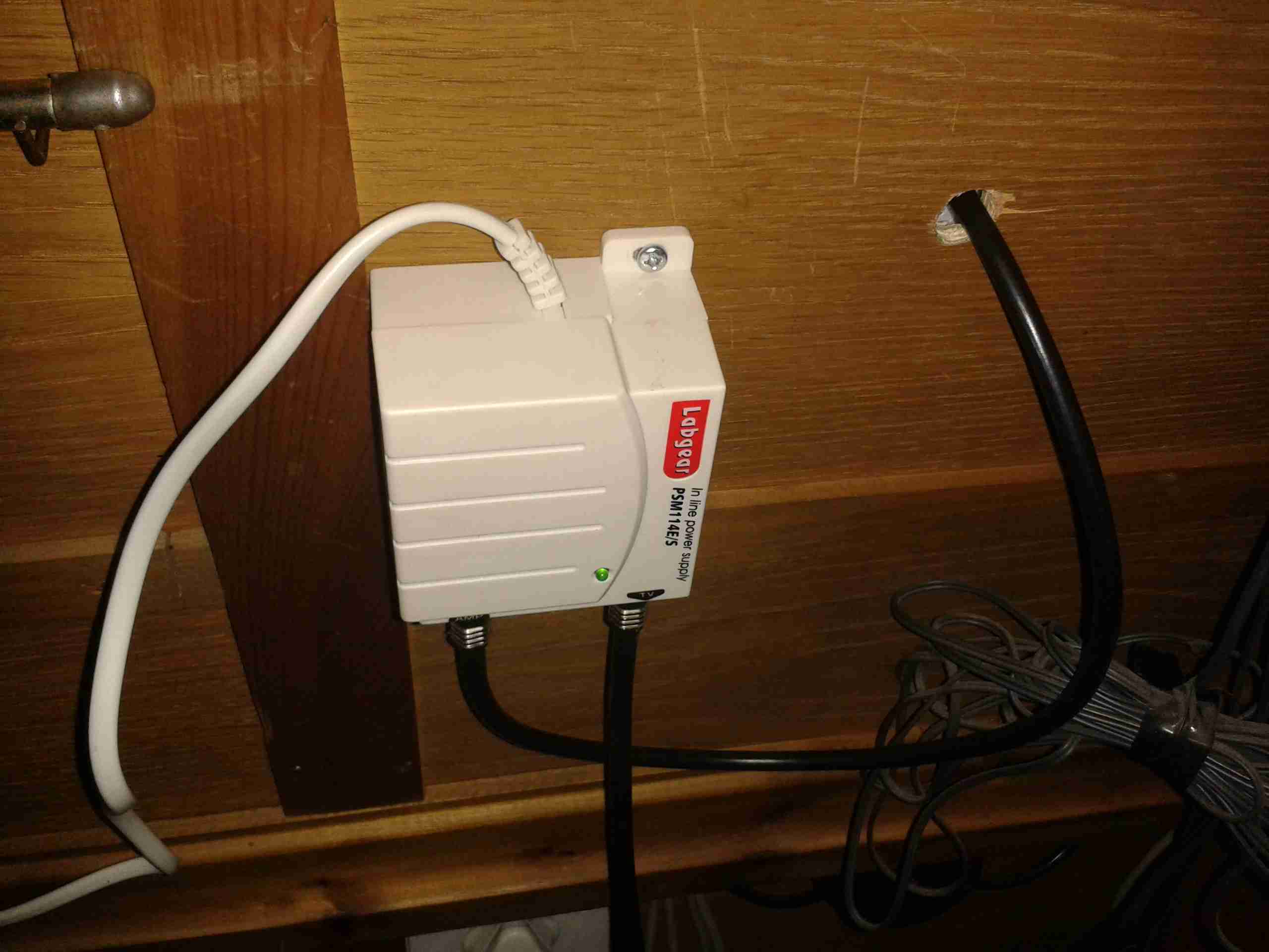
Here’s the power supply, mounted behind the TV where the cable comes through the hull.
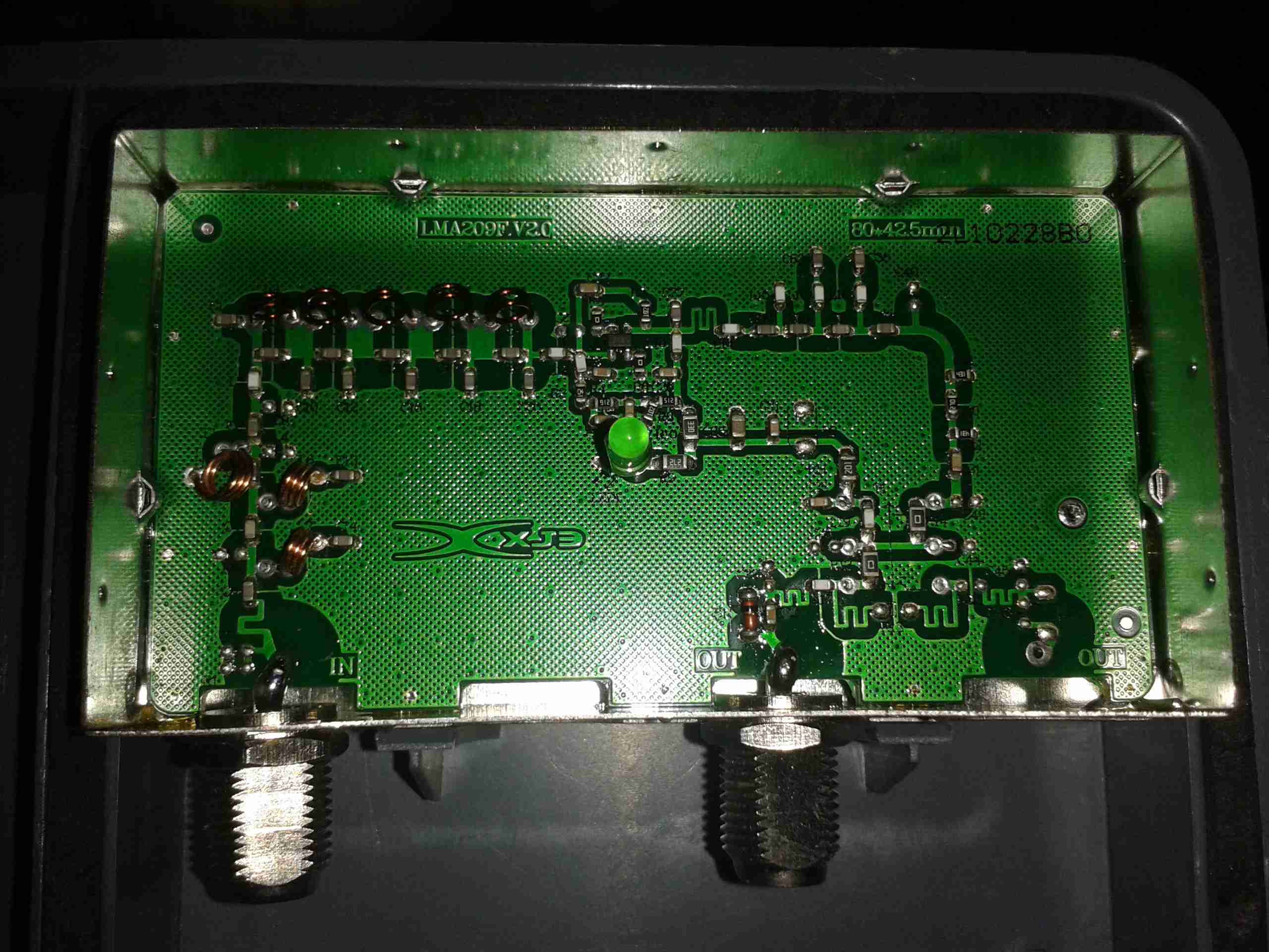
Here’s the inside of the amplifier module. It’s very simple, with some input filtering to block out 4G mobile signals, and a single amplifier transistor.
I think the headline speaks for itself… The usual group, with their Baofengs… Grossly over on the power!
One bit of my equipment that I’ve never looked into is my scanner, a handheld Uniden unit. I got this when Maplin Electronics had them on special offer a few years ago.
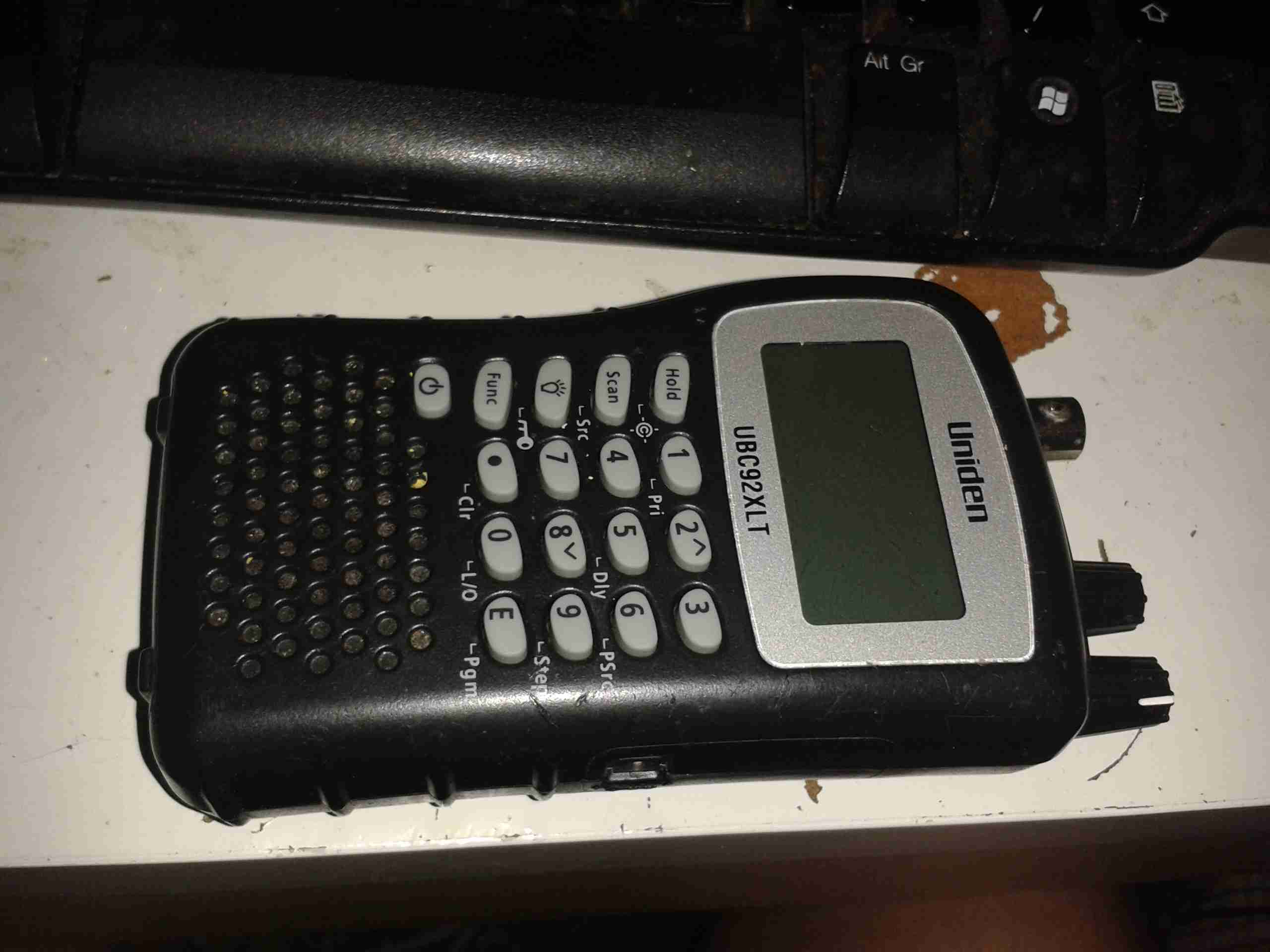
Here’s the scanner itself, roughly the same size as a usual HT.
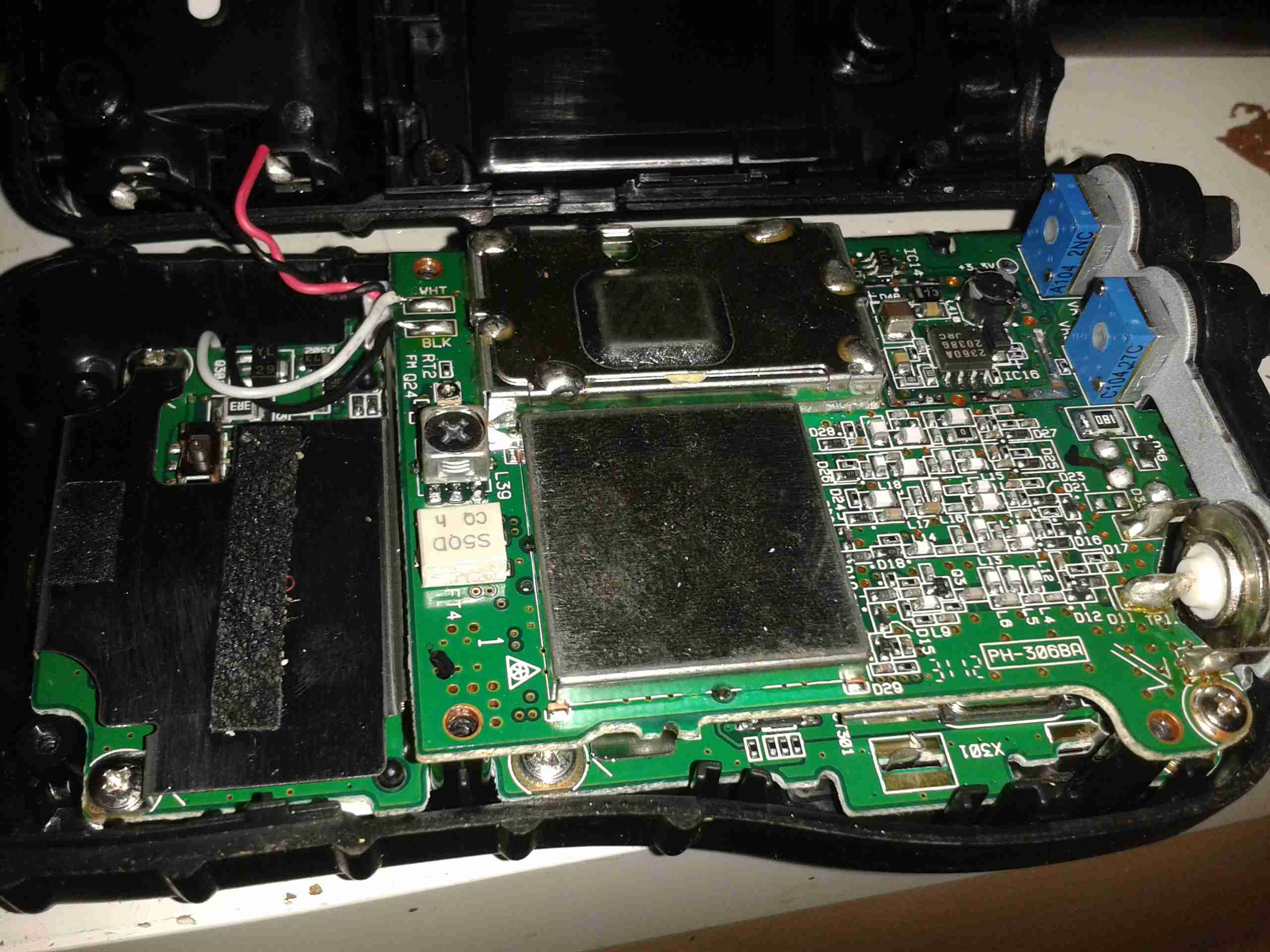
Here the back cover has been removed, and the main RF board is visible at the top of the stack. Unfortunately the shielding cans are soldered on this unit, so no looking under there 🙁
On the right hand side of the board next to the antenna input is the main RF filter network, and it’s associated switching. The RF front end is under the shield closest to the front edge.
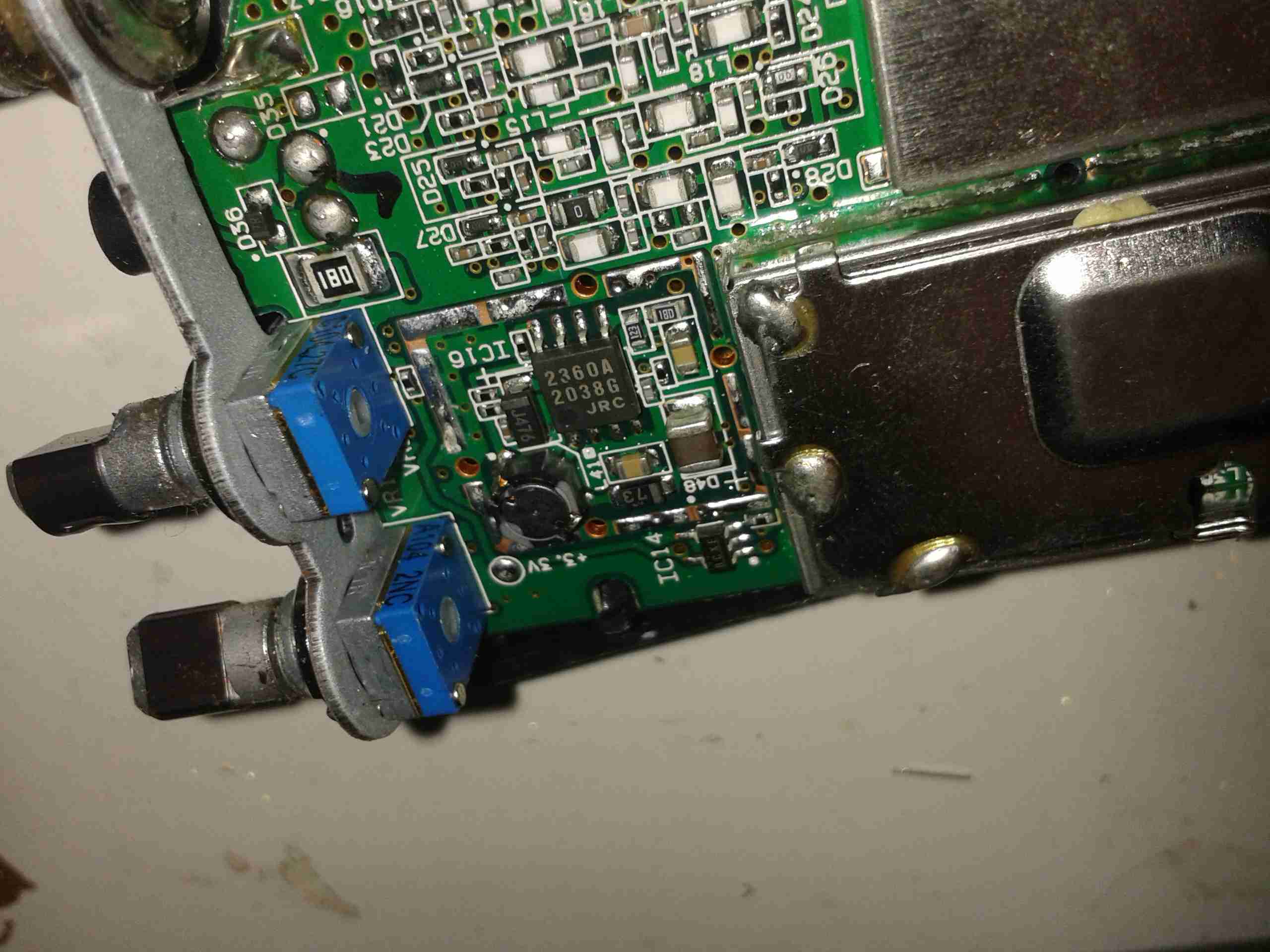
On the other side of the PCB is the Volume & Squelch potentiometers, along with a dedicated 3.3v switching supply. An NJM2360A High Precision DC/DC converter IC controls this one. A 3.3v test point is visible next to the regulator.
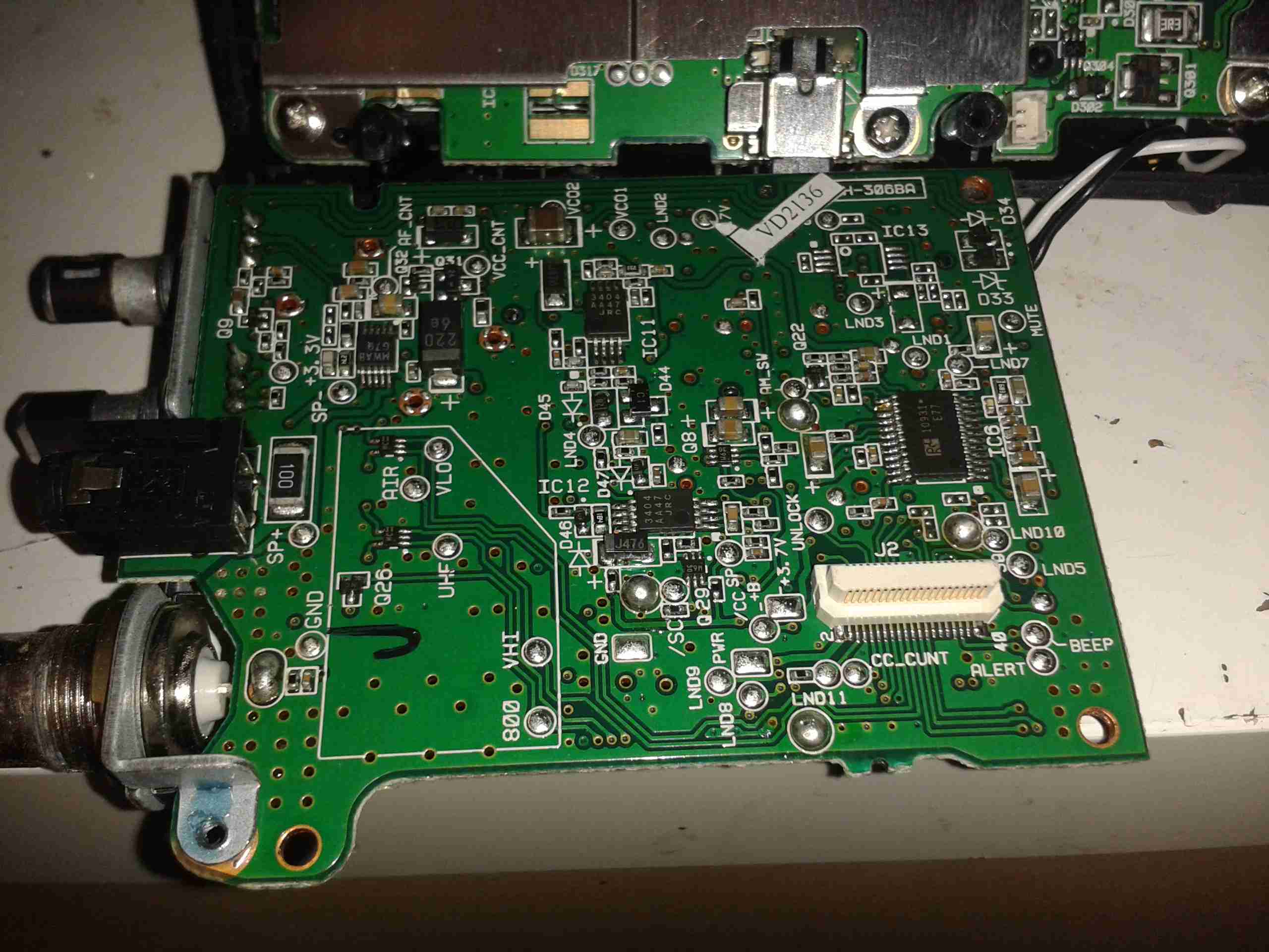
Here’s the backside of the RF board, some more interesting parts here. There’s a pair of NJM3404A Single Supply Dual Op-Amp ICs, and a TK10931V Dual AM/FM IF Discriminator IC. This is the one that does all the back-end radio functionality. The audio amplifier for the internal speaker & external headphone jack is also on this PCB, top left. A board-to-board interconnect links this radio board with the main control board underneath.
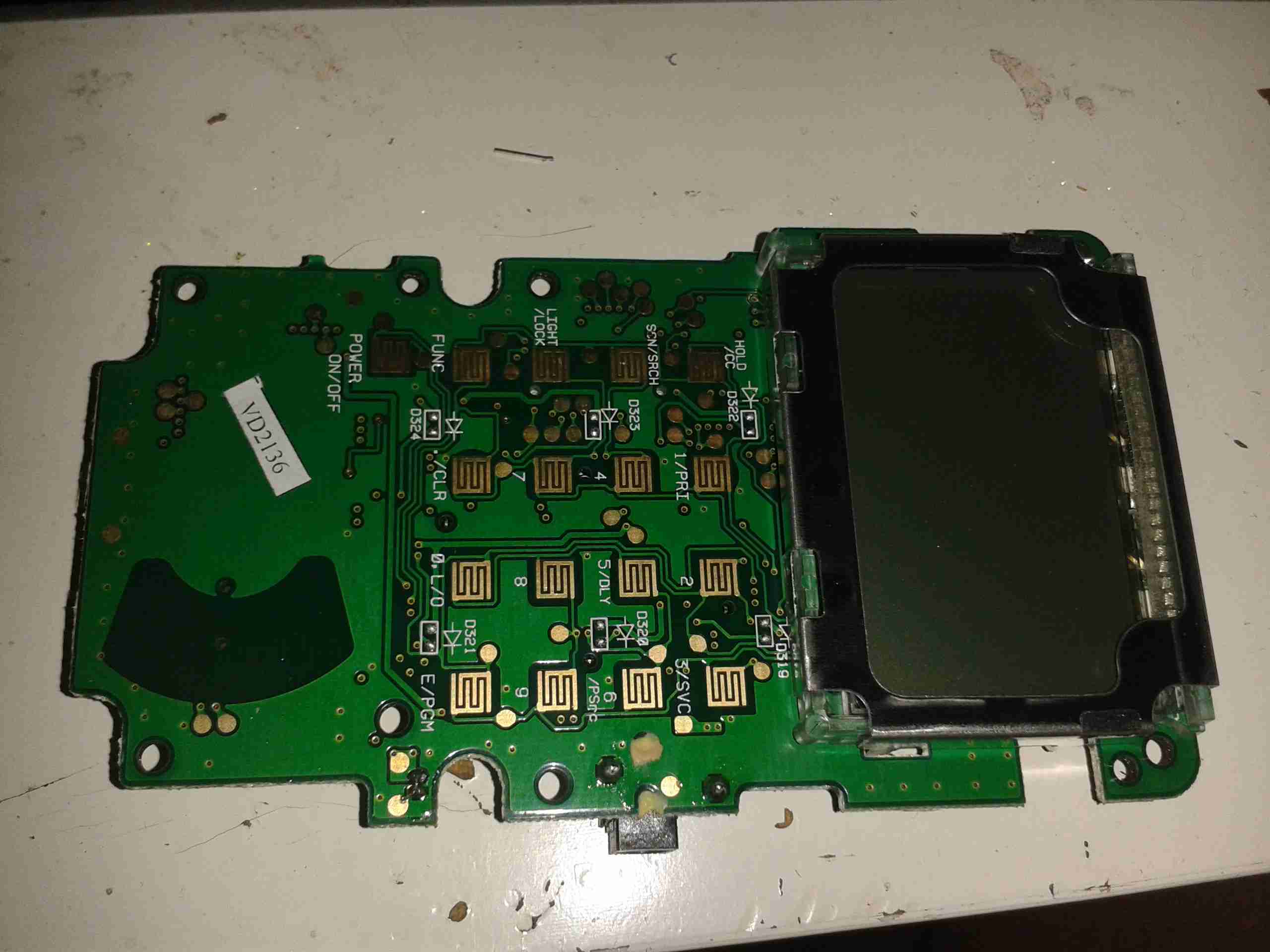
Here’s the front of the control PCB, nothing much to see here, just the LCD & membrane keypad contacts.
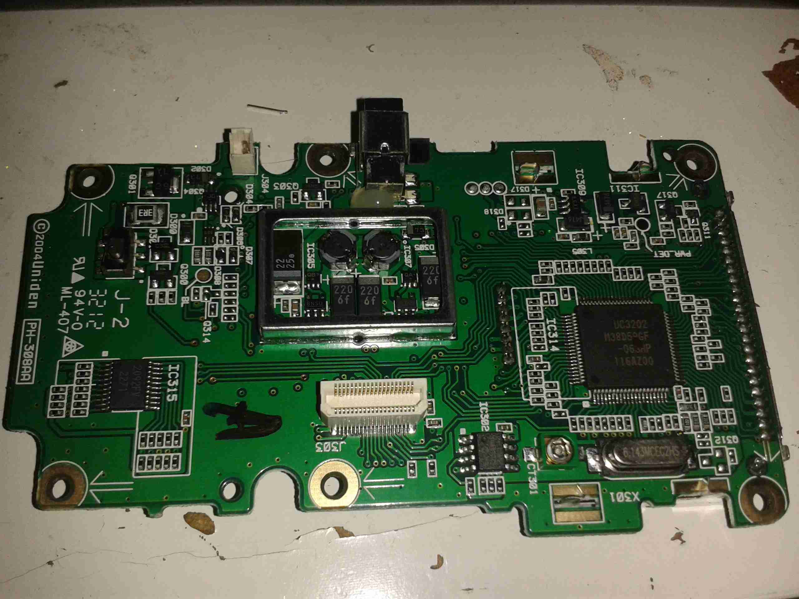
And here’s the reverse side of the control board. All the interesting bits are here. The main microcontroller is on the right, a Renesas M38D59GF, a fairly powerful MCU, with onboard LCD drive, A/D converter, serial interface, 60K of ROM & 2K of RAM. It’s 6.143MHz clock crystal is just below it.
The mating connector for the RF board is in the centre here.
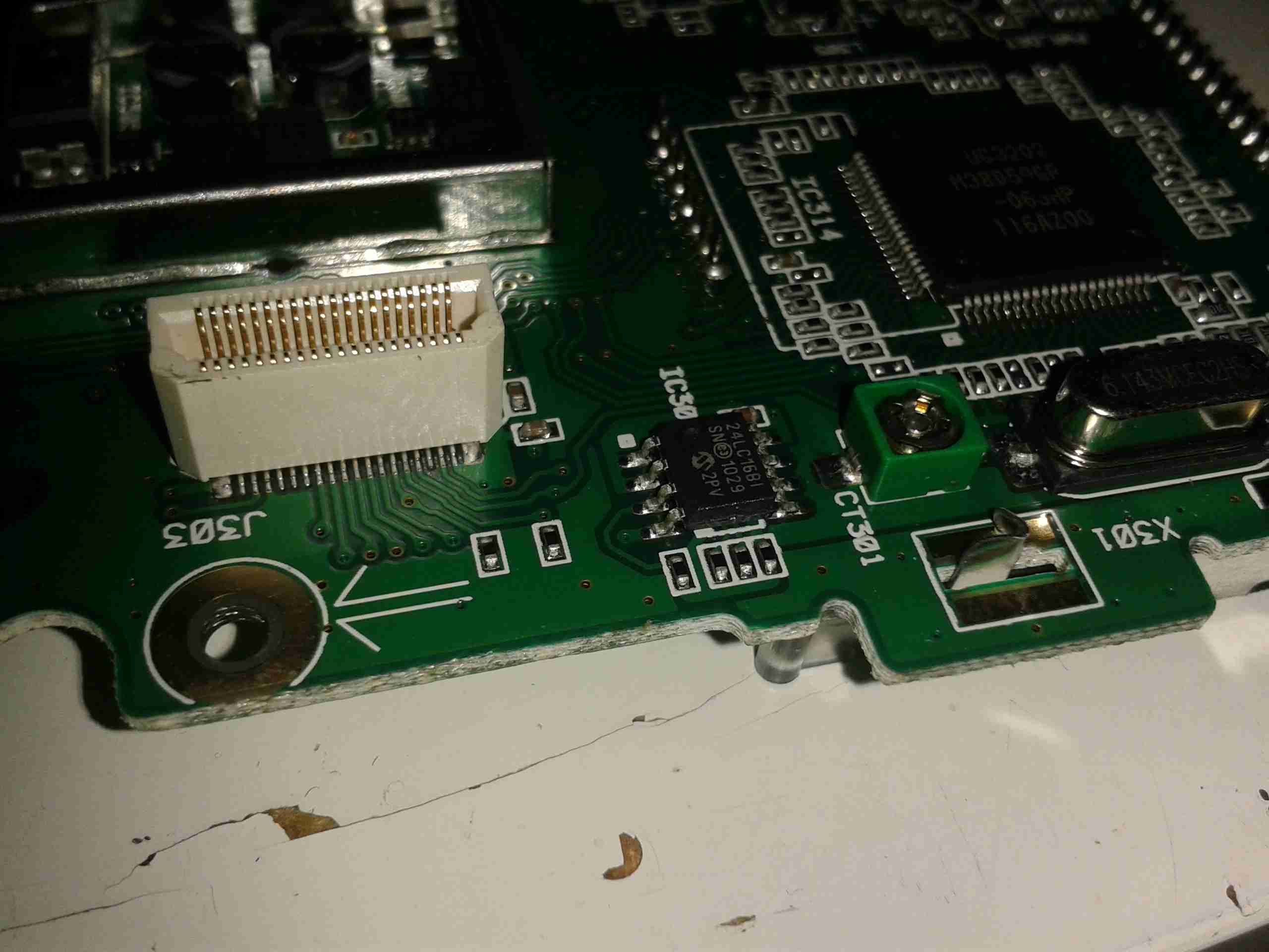
There is also a Microchip 24LC168 16KB I²C EEPROM next to the main microcontroller. This is probably for storing user settings, frequencies, etc.
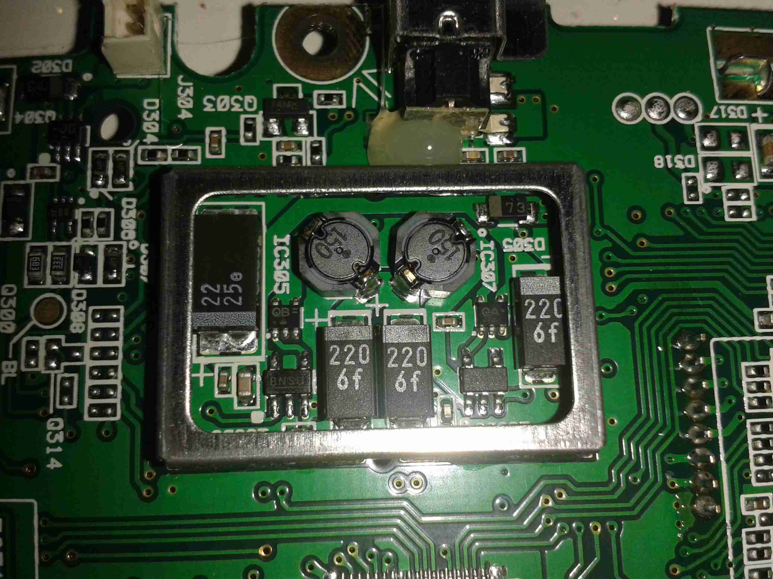
The rest of this board is dedicated to battery charging and power supply, in the centre is a dual switching controller, I can’t figure out the numbers on the tiny SOT23 components in here, but this is dealing with the DC 6v input & to the left of that is the circuitry for charging the NiMH cells included with the scanner.
The last bit of this PCB is a BU2092FV Serial In / Parallel Out 4 channel driver. Not sure what this one is doing, it might be doing some signal multiplexing for the RF board interface. Unfortunately the tracks from this IC are routed on the inner layers of the board so they can’t be traced out.
A while ago I blogged about modifying the output voltage of some surplus Cisco switch power supplies to operate at 13.8v.
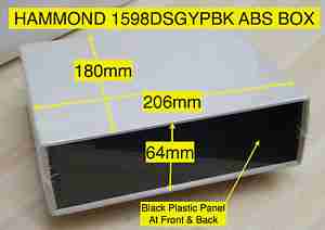
Since I was able to score a nice Hammond 1598DSGYPBK ABS project box on eBay, I’ve built one of the supplies into a nice bench unit.

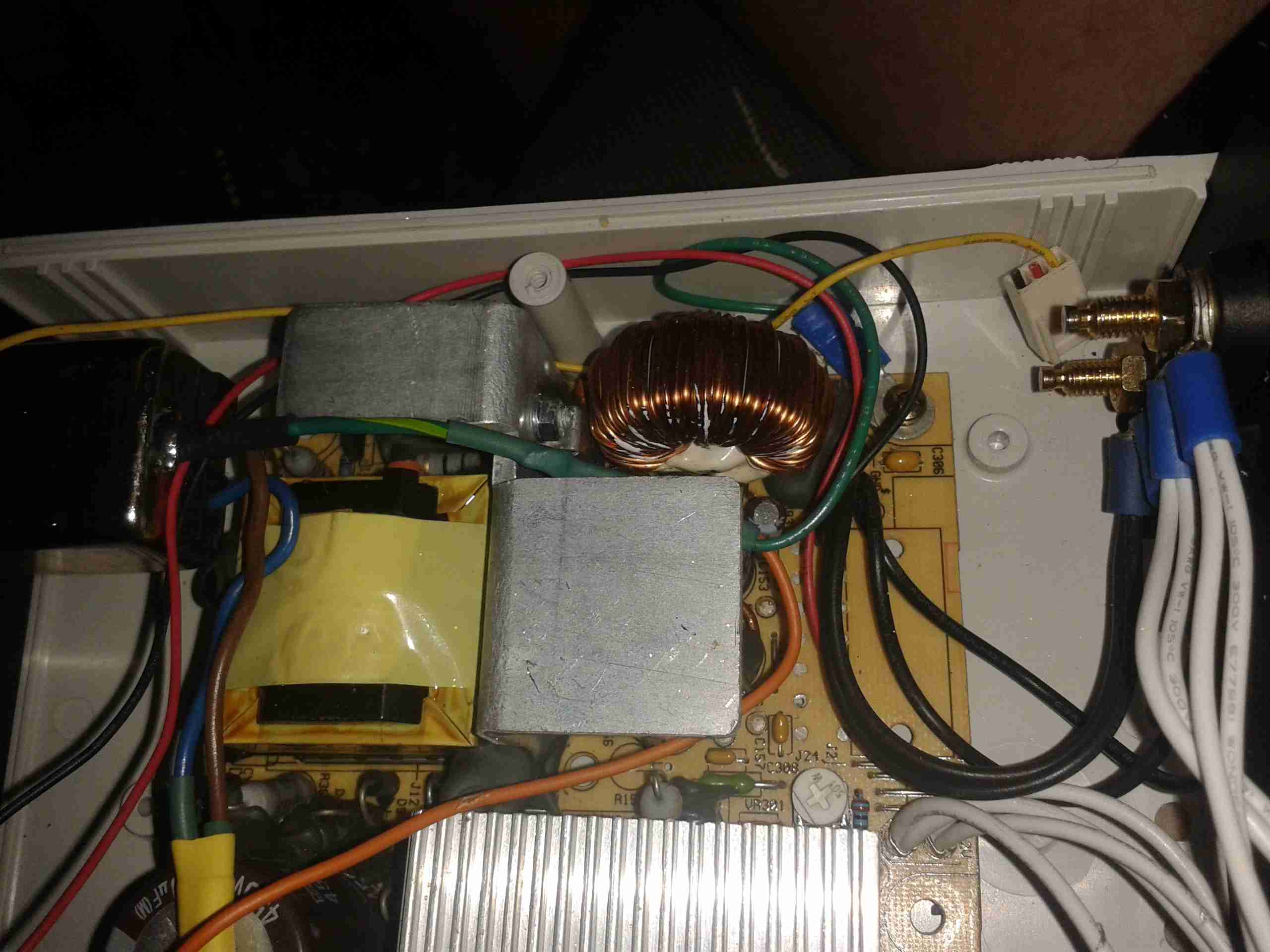
Above is the supply mounted into the box, I had to slightly trim one edge of the PCB to make everything fit, as it was just a couple of mm too wide. Luckily on the mains side of the board is some space without any copper tracks.
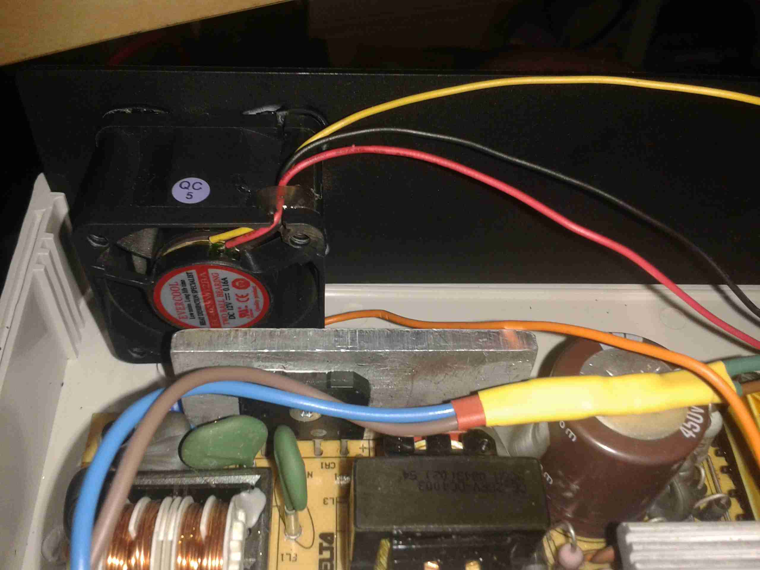
These supplies are very high quality & very efficient, however they came from equipment that was force-air cooled. Running the PSU in this box with no cooling resulted in overheating. Because of this I have added a small 12v fan to move some air through the case. The unit runs much cooler now. To allow the air to flow straight through the case, I drilled a row of holes under the front edge as vents.
Here is the output side of the supply, it uses standard banana jacks for the terminals. I have used crimp terminals here, but they are soldered on instead of crimped to allow for higher current draw. The negative return side of the output is mains earth referenced.
I have tried to measure output ripple on this supply, but with my 10X scope probe, and the scope set to 5mV/Div, the trace barely moves. The output is a very nice & stable DC.
This supply is now running my main radio in the shack, and is small enough to be easily portable when I move my station.
Recently I’ve noticed my usual mobile rig, the Baofeng UV-5R, has had very poor receive, and non-existent transmit.
I did a power test on the radio, and confirmed it was still outputting it’s rated RF power. Trying another antenna proved that the radio was fine.
Time to tear down the antenna & see if it can be fixed!
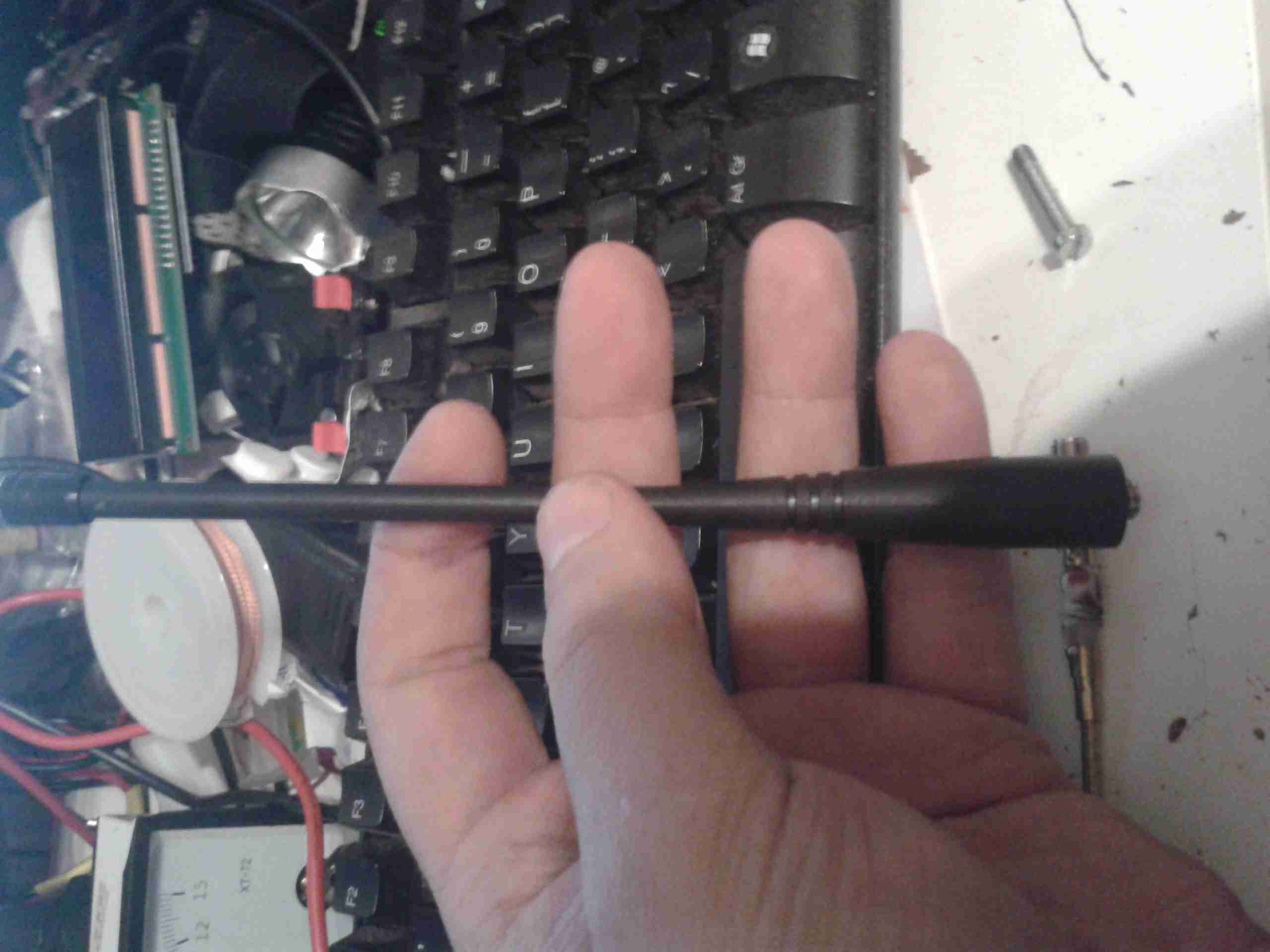
Here’s the antenna, just the factory rubber duckie. As with all these antennas, they’re a compromise between size & their efficiency.
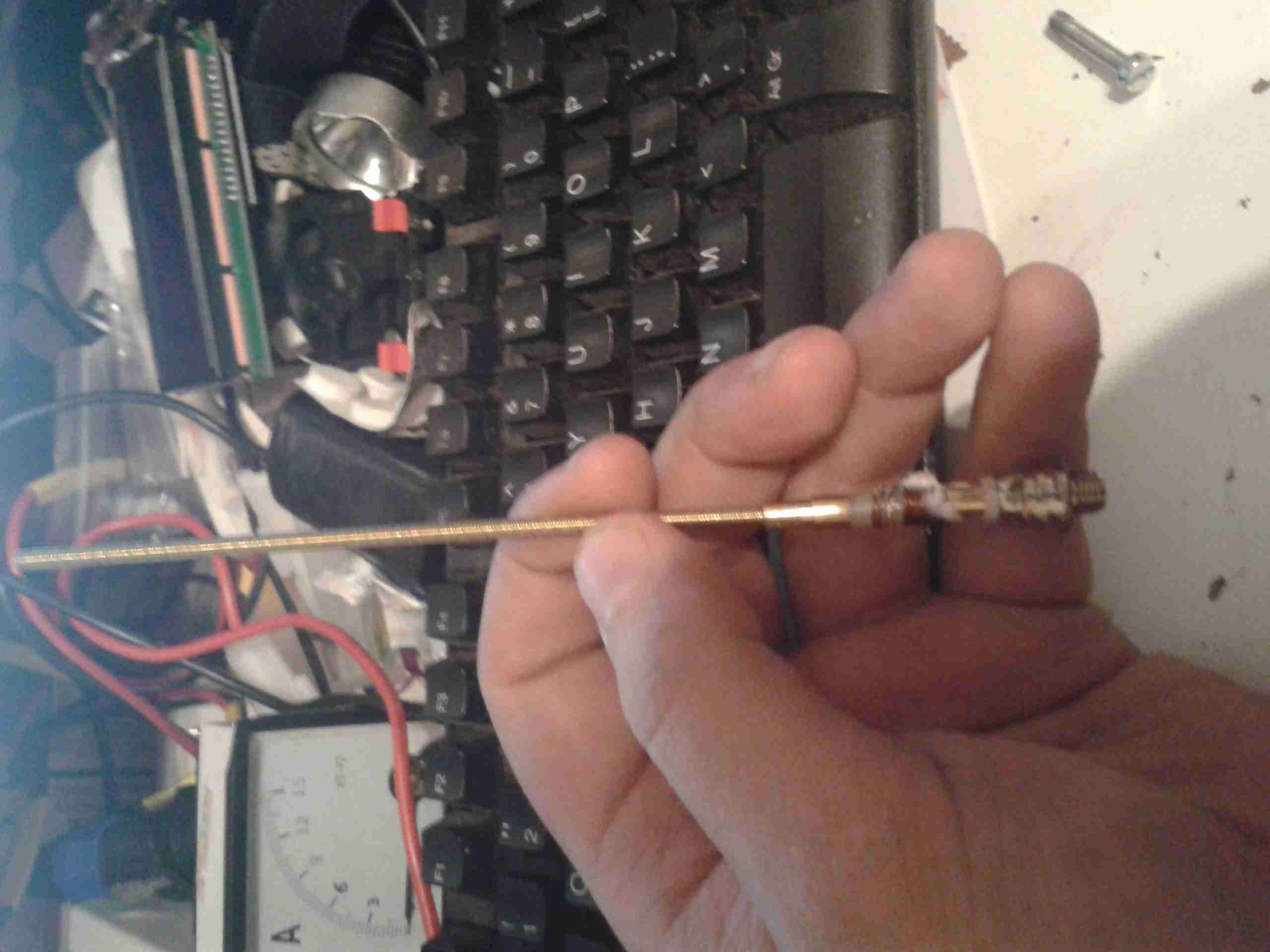
Giving a gentle pull to the antenna sheath while it’s attached to the radio allows it to come apart. The quality actually doesn’t look to bad. It’s very similar in construction to my Diamond X-30, just on a much smaller scale.
At the bottom of the antenna is the matching network, an inductor & ceramic disc capacitor. Here lies the problem with this antenna.
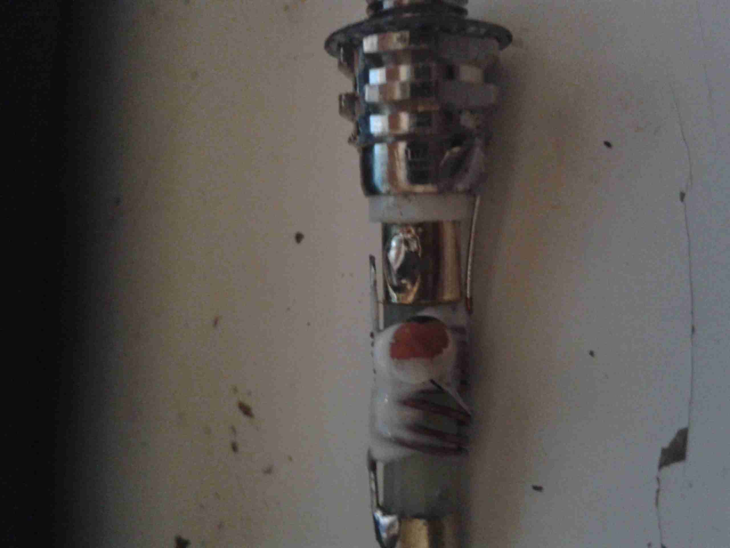
Here where the capacitor joins onto the feedpoint from the SMA connector, the solder joint has come away. This was a very poor joint to start with, and the solder hadn’t wetted the capacitor lead at all
After cleaning the joint, and applying some flux, a new joint was easily made with some Real Solder.
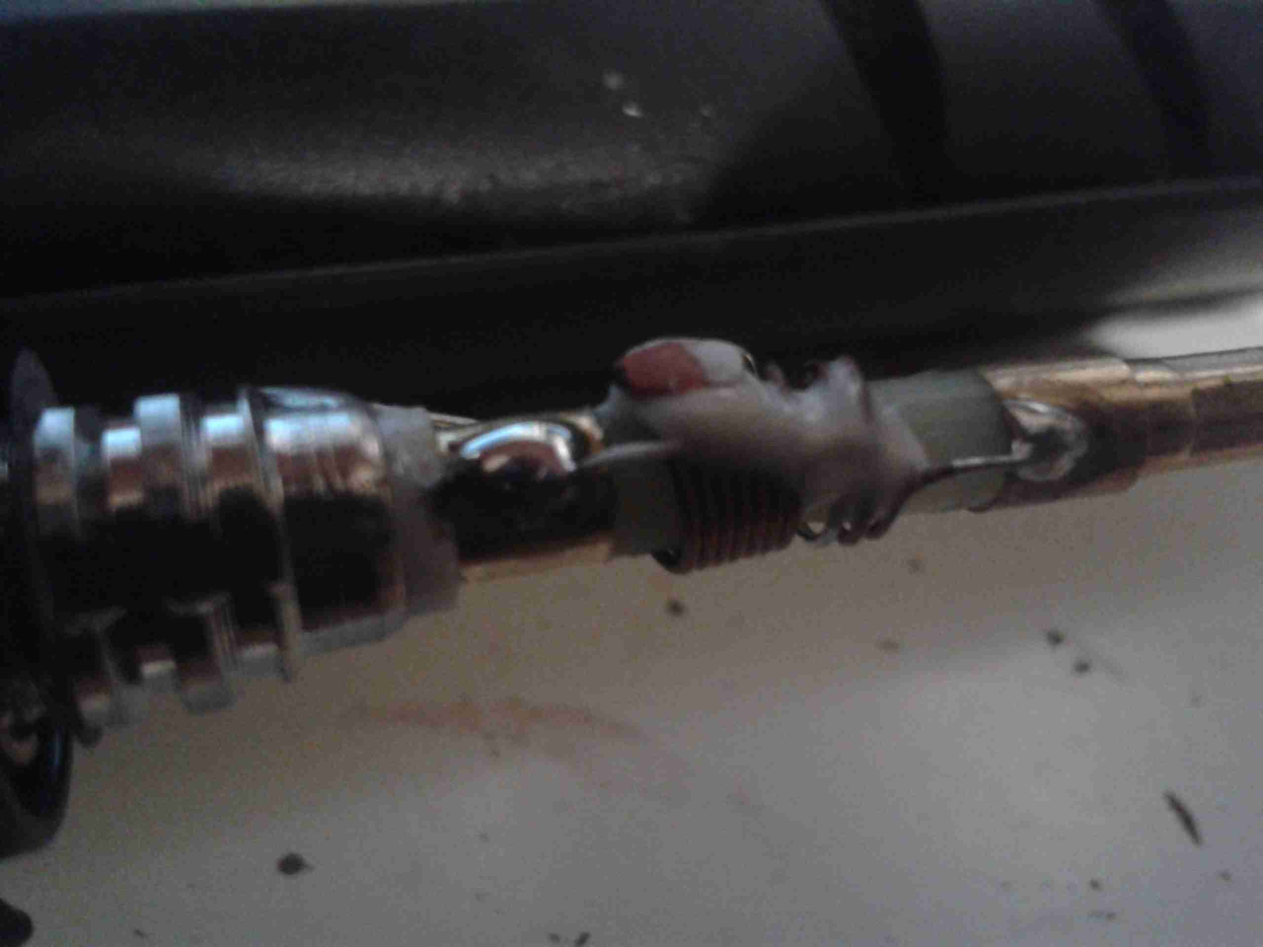
Here’s the joint freshly repaired, the antenna is now back to full working order. It even seems to work better than the others I have 🙂
I’ve always found programming repeaters into the UV-5R manually a bit of an arse, especially since the manual is pretty poor & very concise. Ringway Manchester have done a very good video detailing a simple way to get this done without a computer & most importantly, without any headaches!
Now the final bits have arrived for the SWR Meter module, I can do the final assembly.
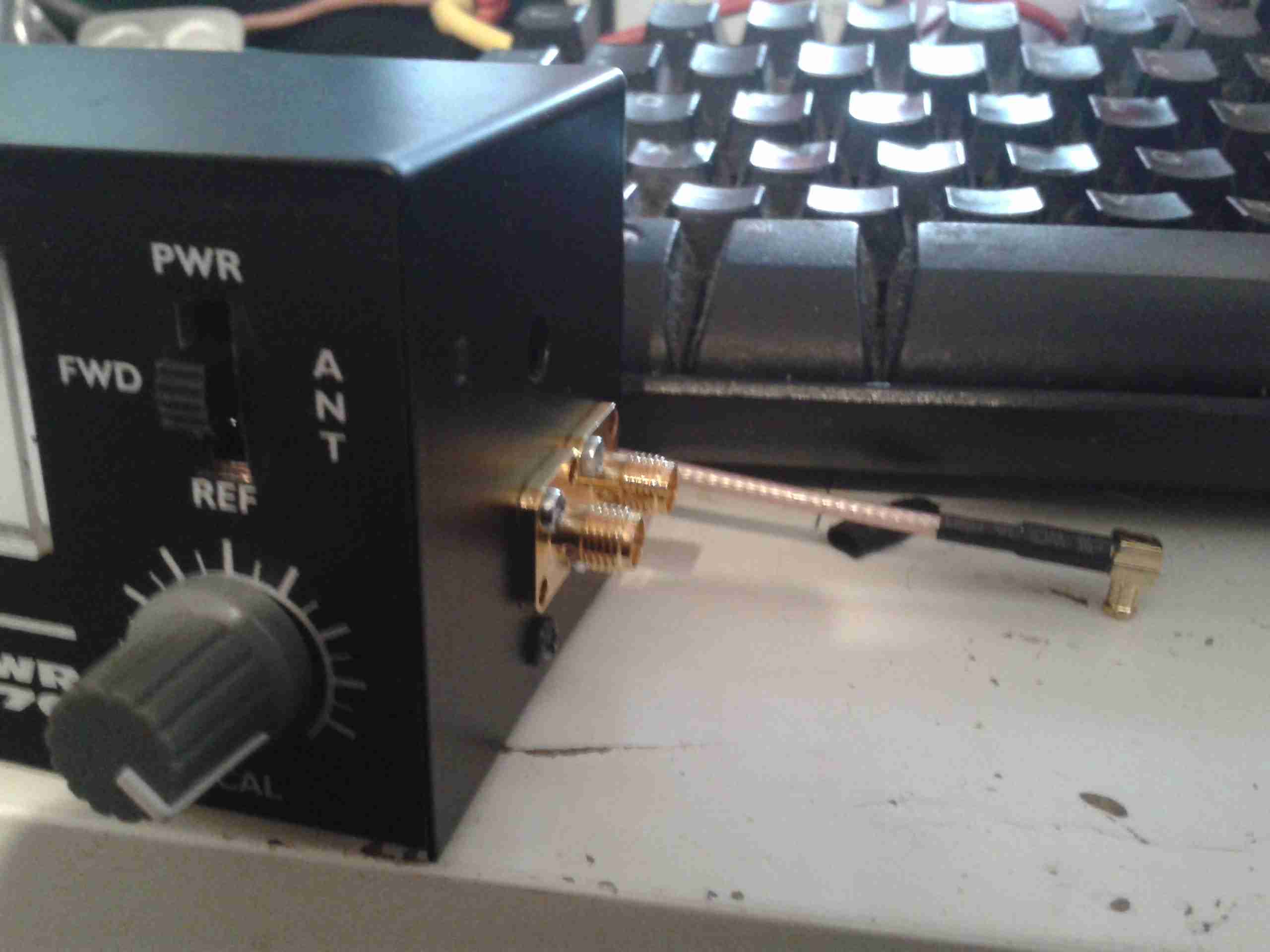
Here the SMA connectors are installed on the side of the eBay meter, for forward & reverse power tap.
These are simply tee’d off the wiring inside the meter where it connects to the switch.
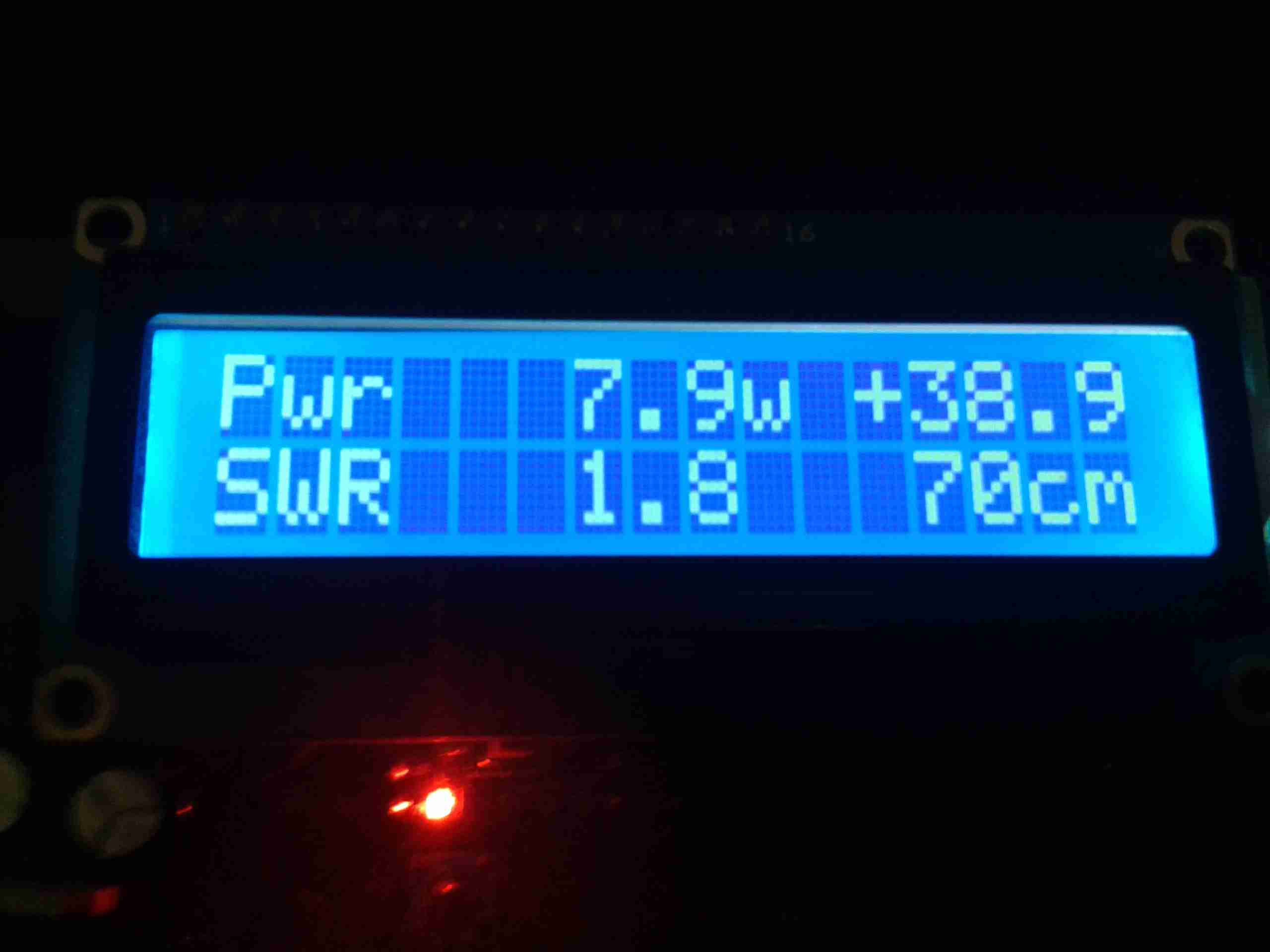
The meter is connected to the module via a pair of RG58 SMA leads, above is a readout before calibration, using one of my Baofeng UV-5Rs.
I’m using my GY561 eBay Power Meter as a calibration source, and as this isn’t perfect, the readings will be slightly off. If I can get my hands on an accurate power meter & dummy load I can always recalibrate.
Tools are only as accurate as the standard they were calibrated from!
After calibration, here’s the readings on 2m & 70cm. These readings coincide nicely with the readings the GY561 produce, to within a couple tenths of a watt. SWR is more than 1:1 as the dummy load in the GY561 isn’t exactly 50Ω.
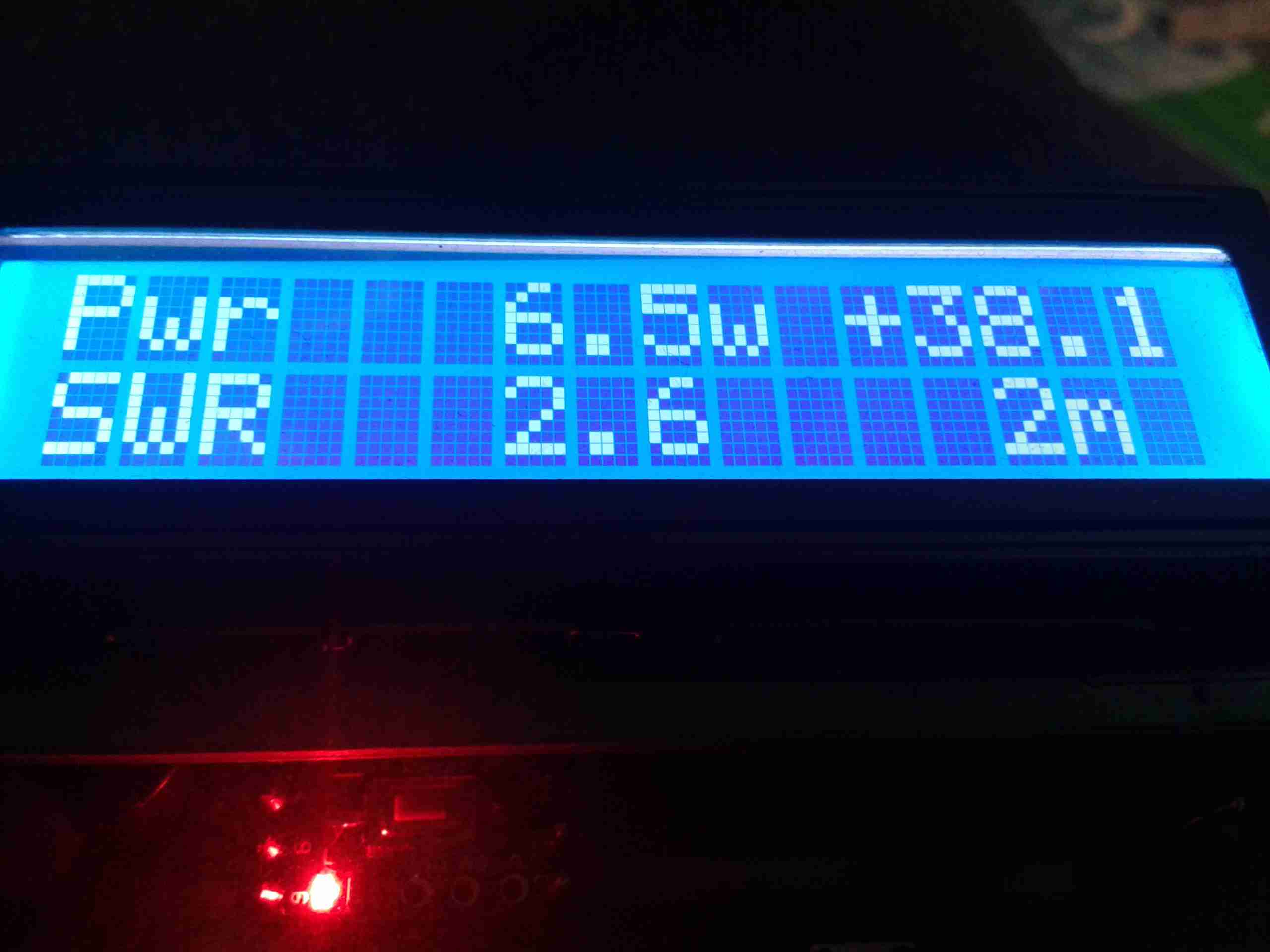
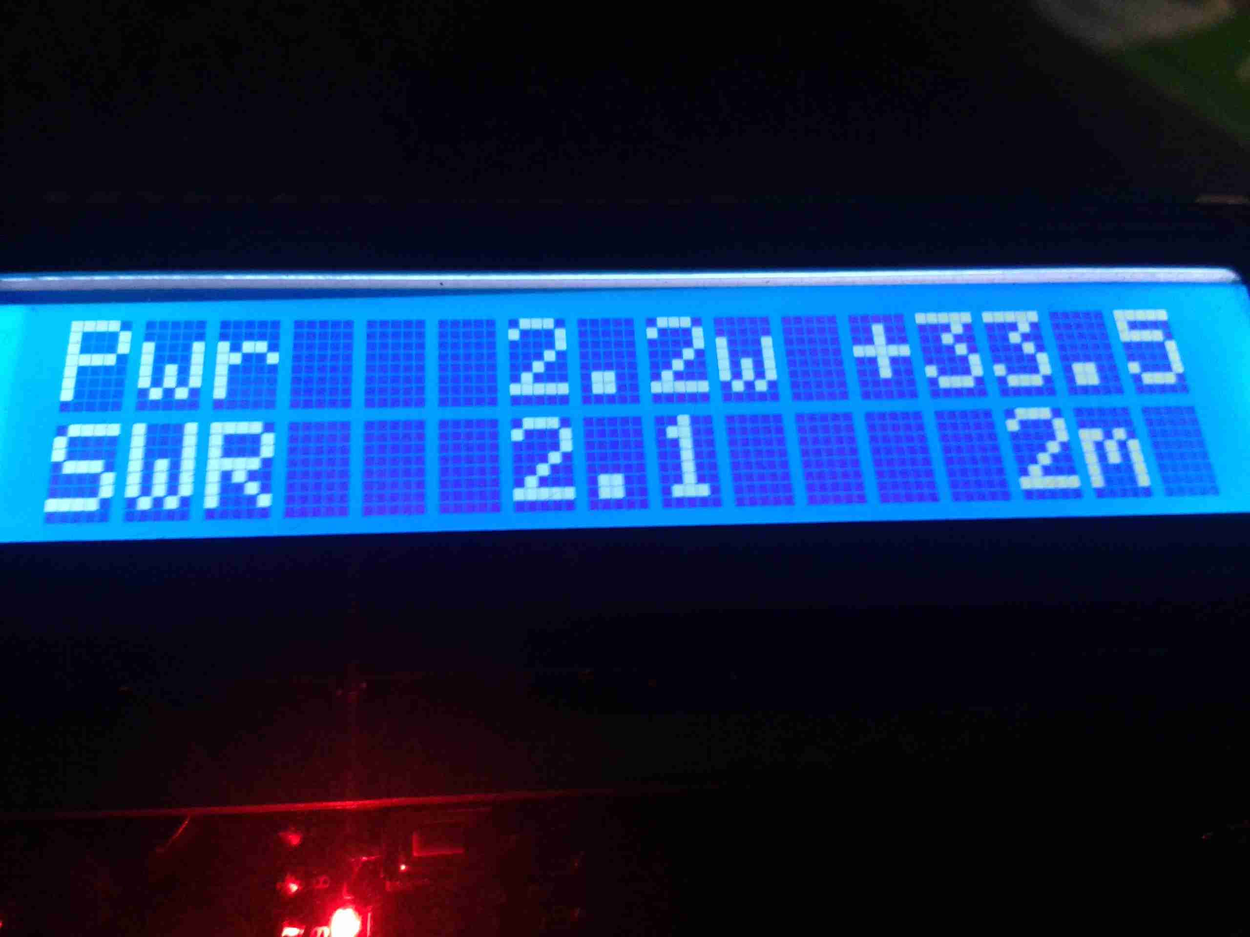
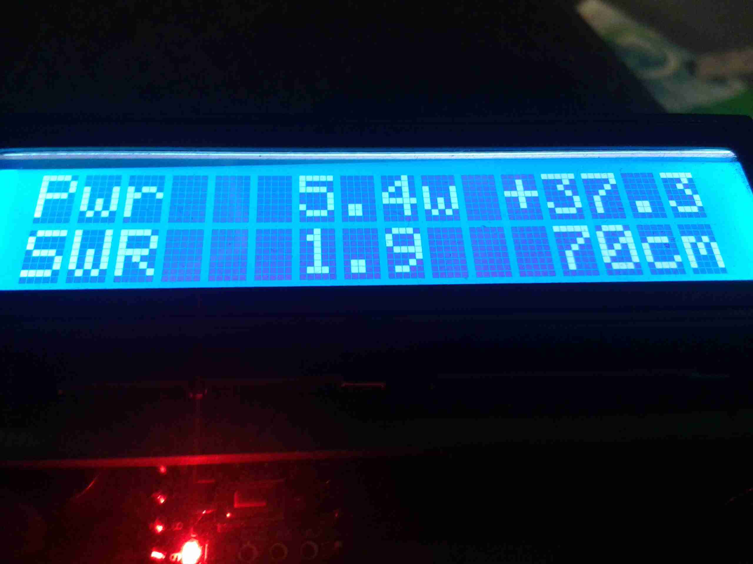
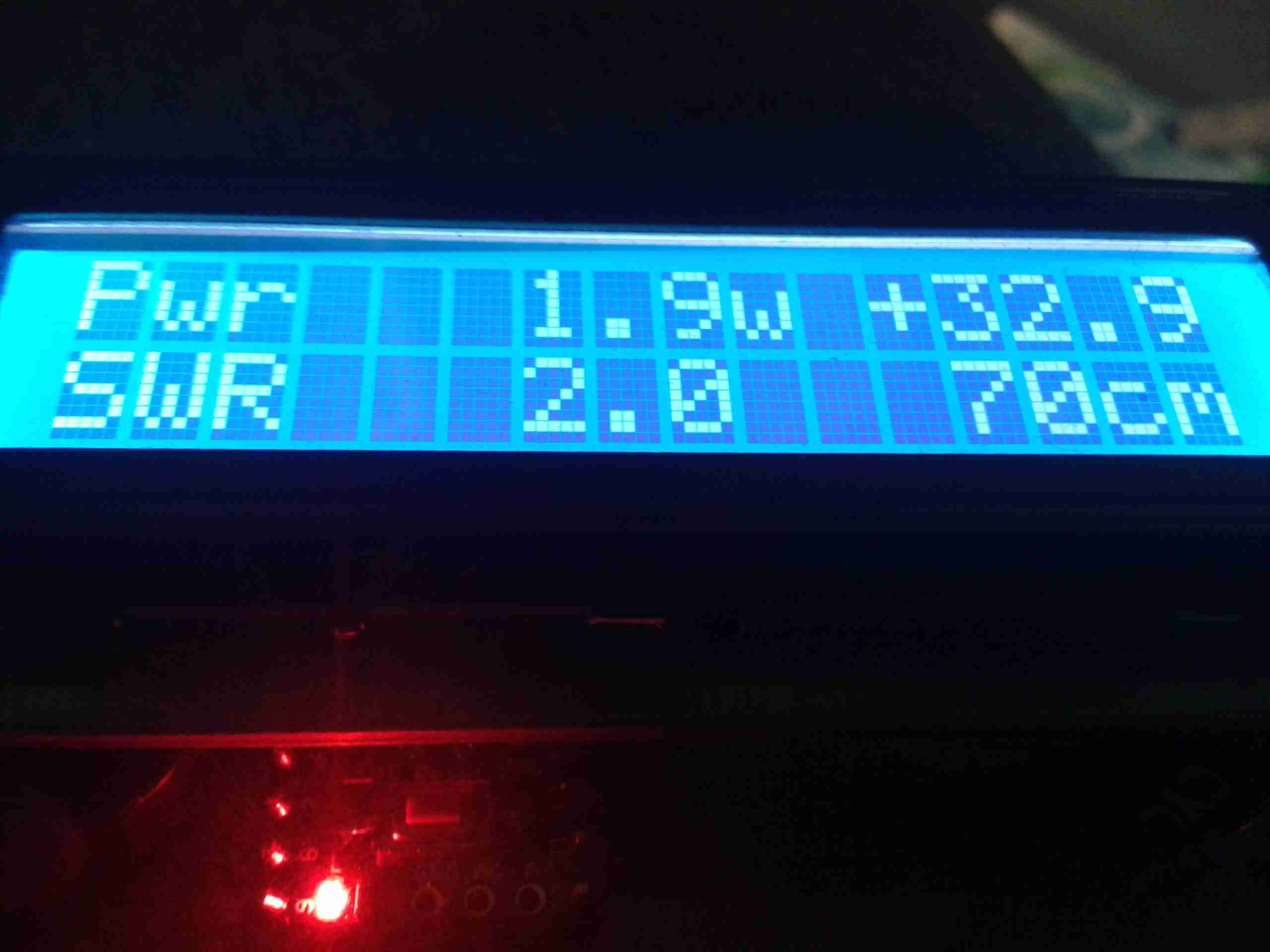
Shortly I’ll calibrate against 6m & 10m so I can use it on every band I have access to 🙂
Here’s some audio from last night on PMR, the regular group seem to be getting a little hacked off 🙂
Onboard the boat we have a small issue with a weak TV signal, and this coupled with a 60′ long run of coax is an issue. Due to the loss in the coax, we’ve lost most of the already weak signal.
To try & solve this issue, I’m fitting a masthead amplifier unit.
These amplifiers are fed power down the same coax that’s carrying the RF signal, and a special power supply is supplied with the amplifier for this. However it’s only 240v AC, no 12v version available.
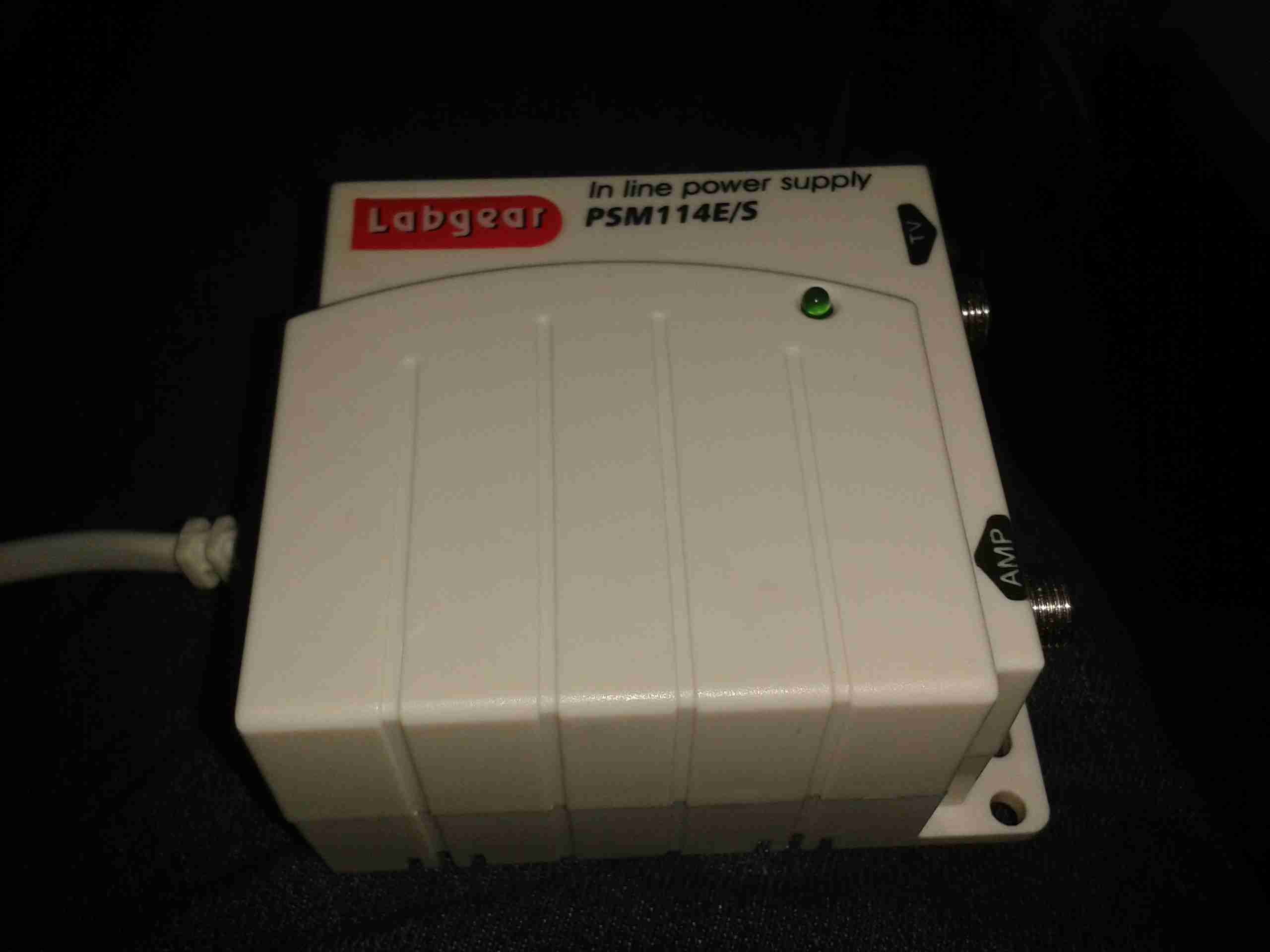
Here’s the power supply unit, which fits into the coax between the TV & the antenna.
Luckily the 240v supply is easily removable & here has been replaced with a 12v regulator.
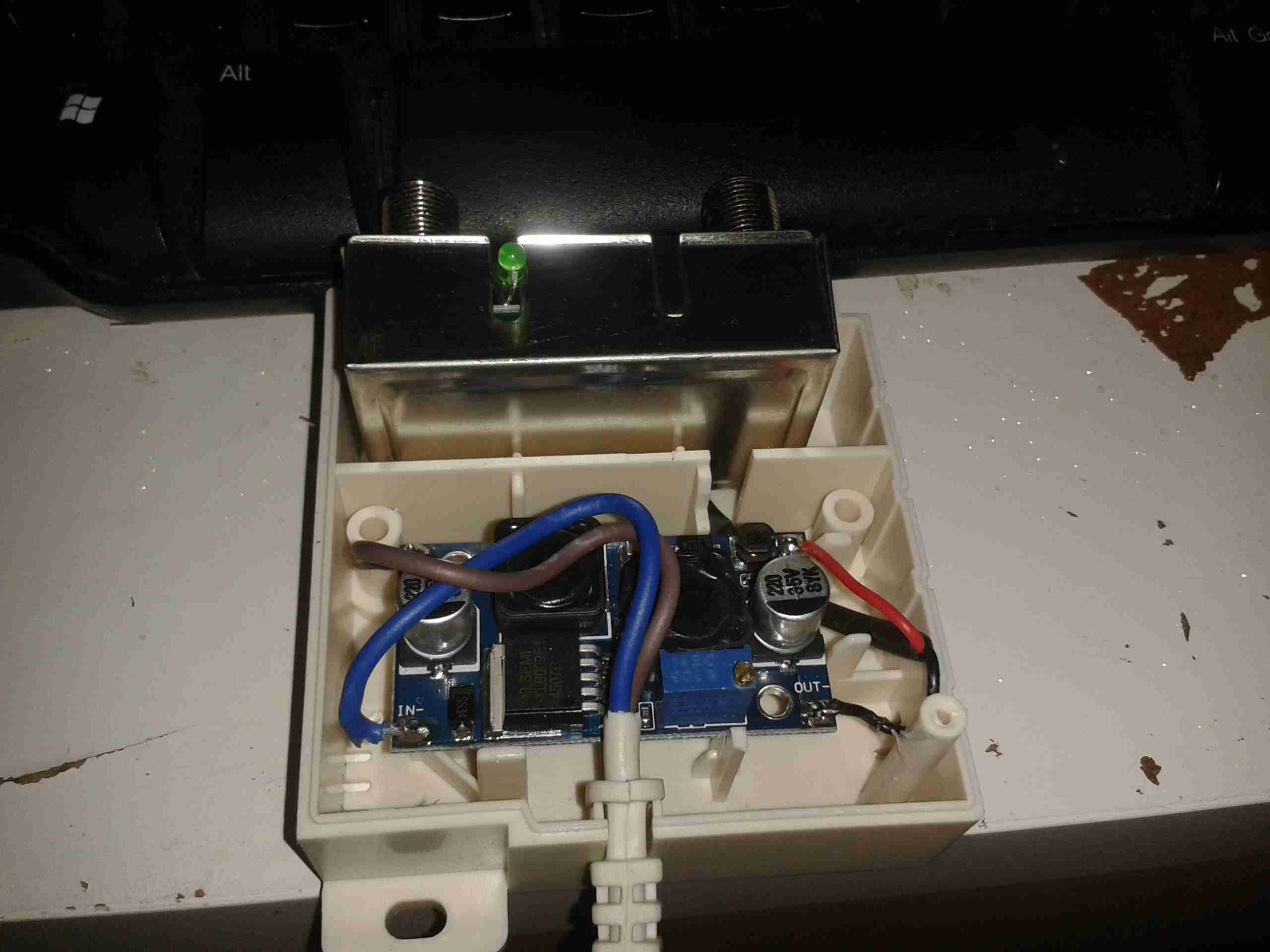
There’s not very much inside the shielding can, just a few filter capacitors & an RF choke on the DC feed, to keep the RF out of the power supply system.
The original cable is used, so the supply doesn’t even look like it’s been modified from the outside.
More to come on this when I get the amplifier installed along with the new coax run 🙂
73s
I thought I’d detail the process I use to fit an N-Type connector to a coax cable, as I don’t usually solder these connectors.
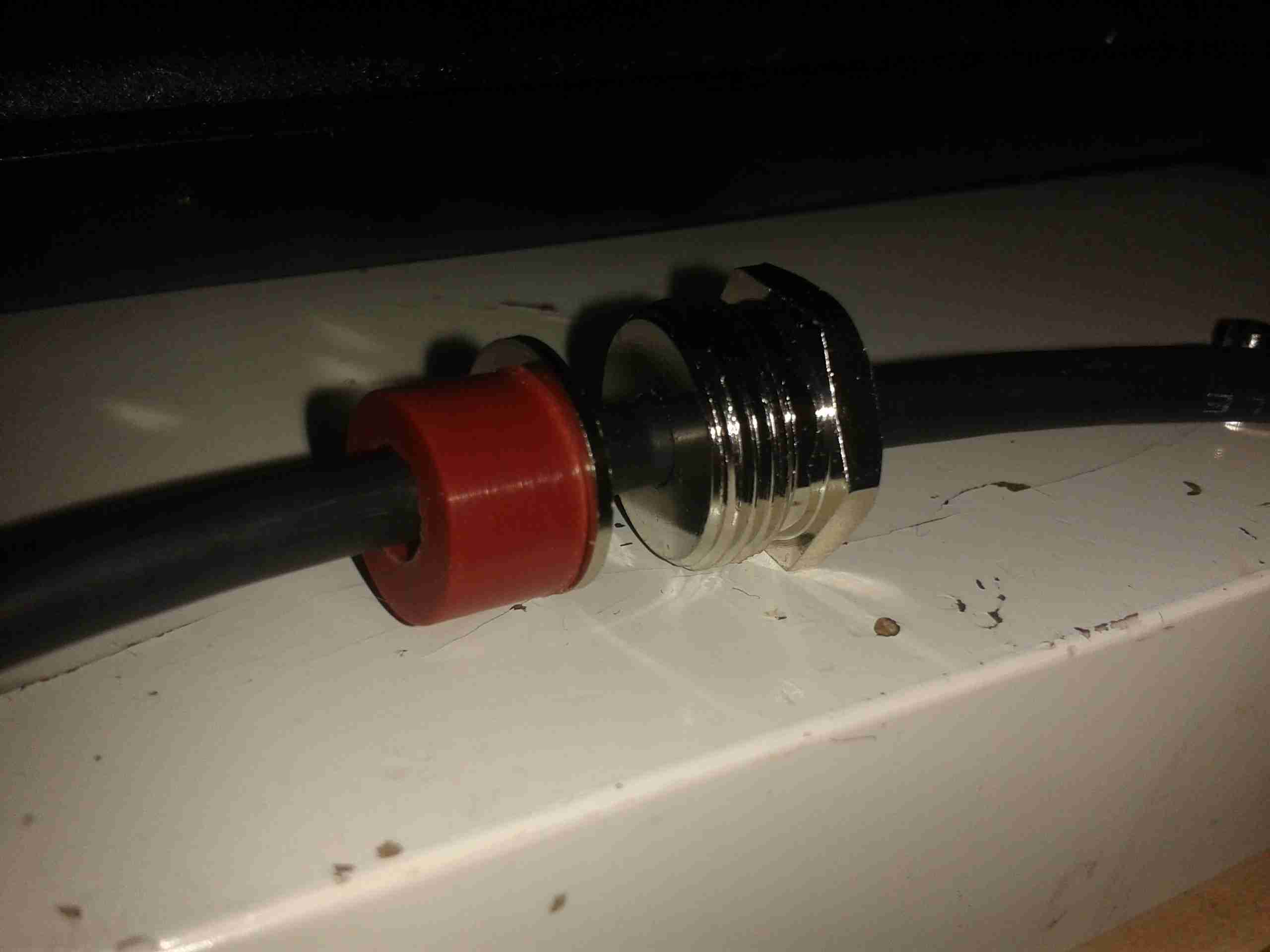
Before stripping, fit the backnut, washer & rubber seal onto the cable.
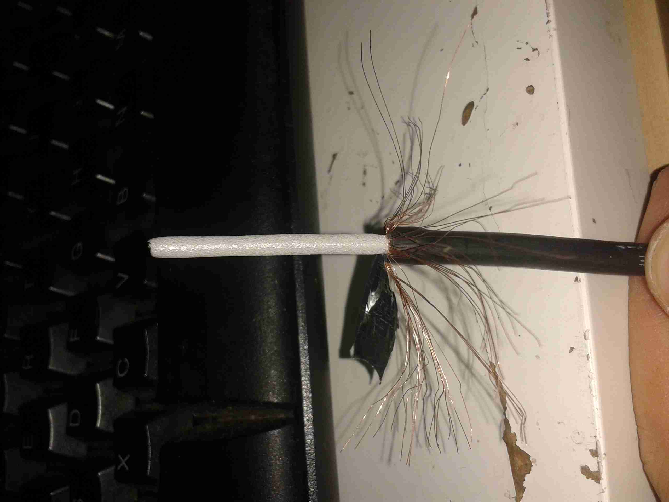
The cable is first stripped back to reveal the shield. This cable has a foil tape as well as the usual copper braid.
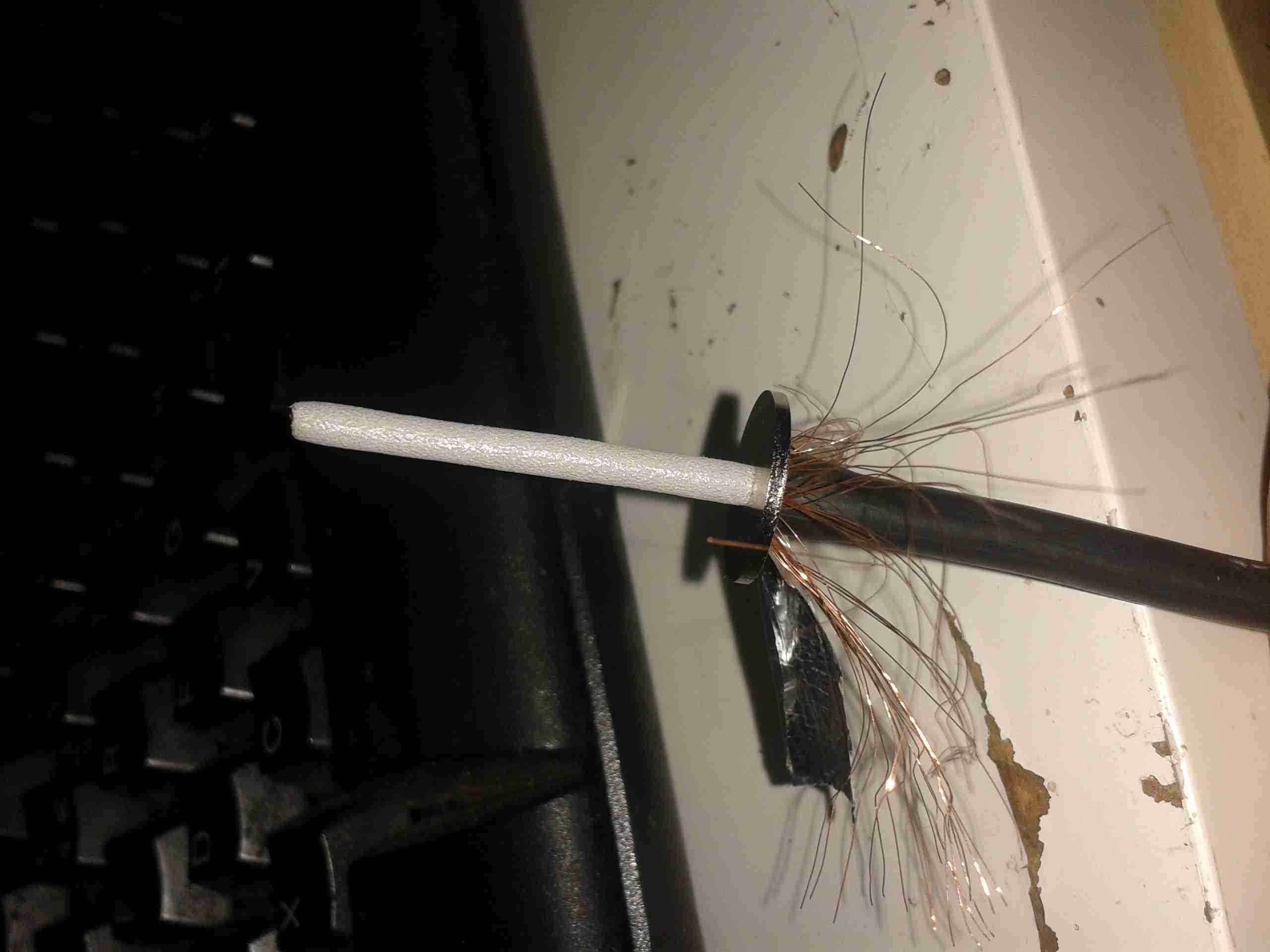
Once the inner core has been revealed, the shield washer is fitted. This has a knife edge on the inner diameter, to fit between the outer sheath & the shield, this makes the electrical connection.
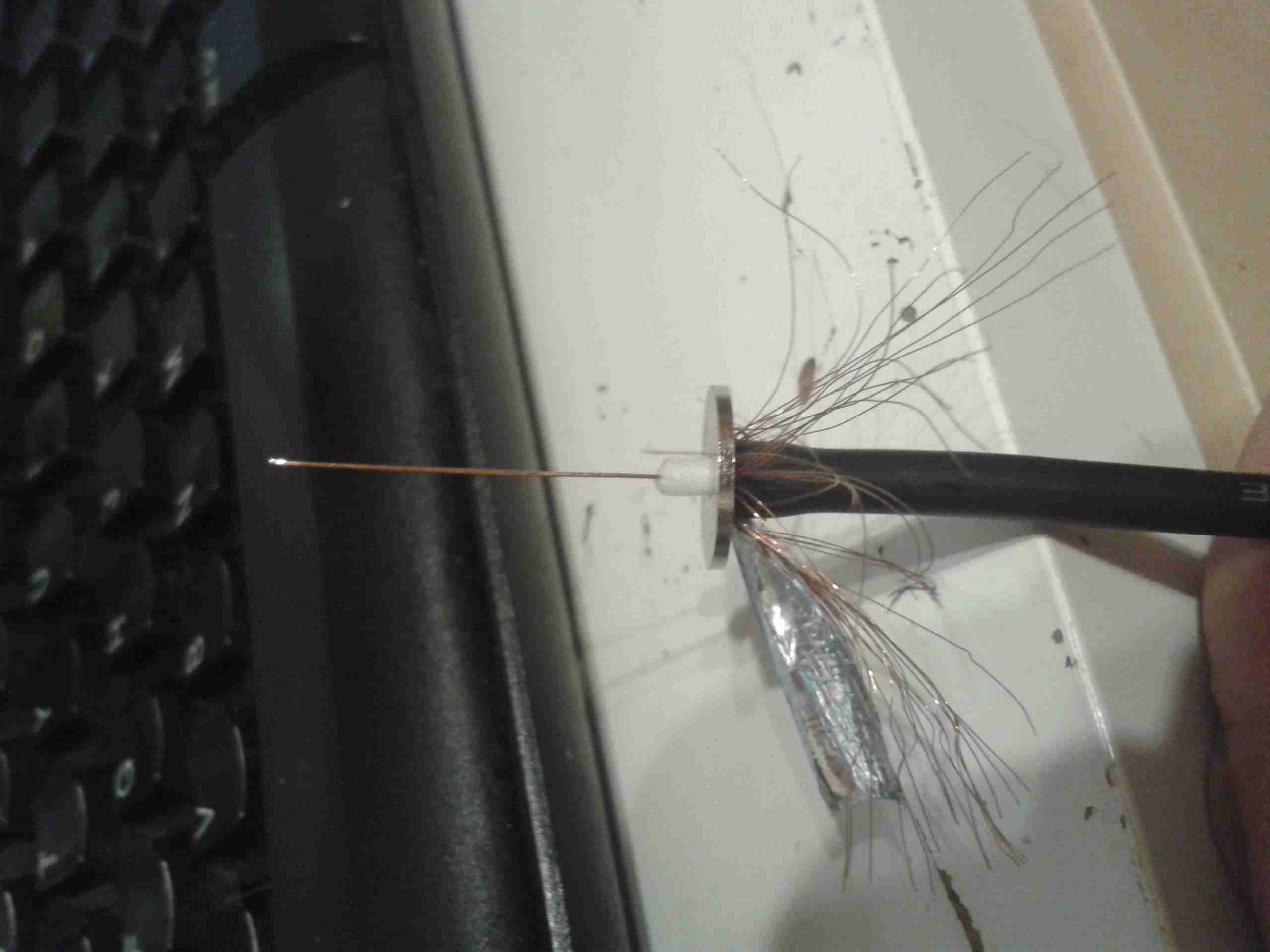
With the shield washer fitted, the inner insulation can be cut back, it should be just about level with the final washer when you’re done, this allows the connector to fit together properly.
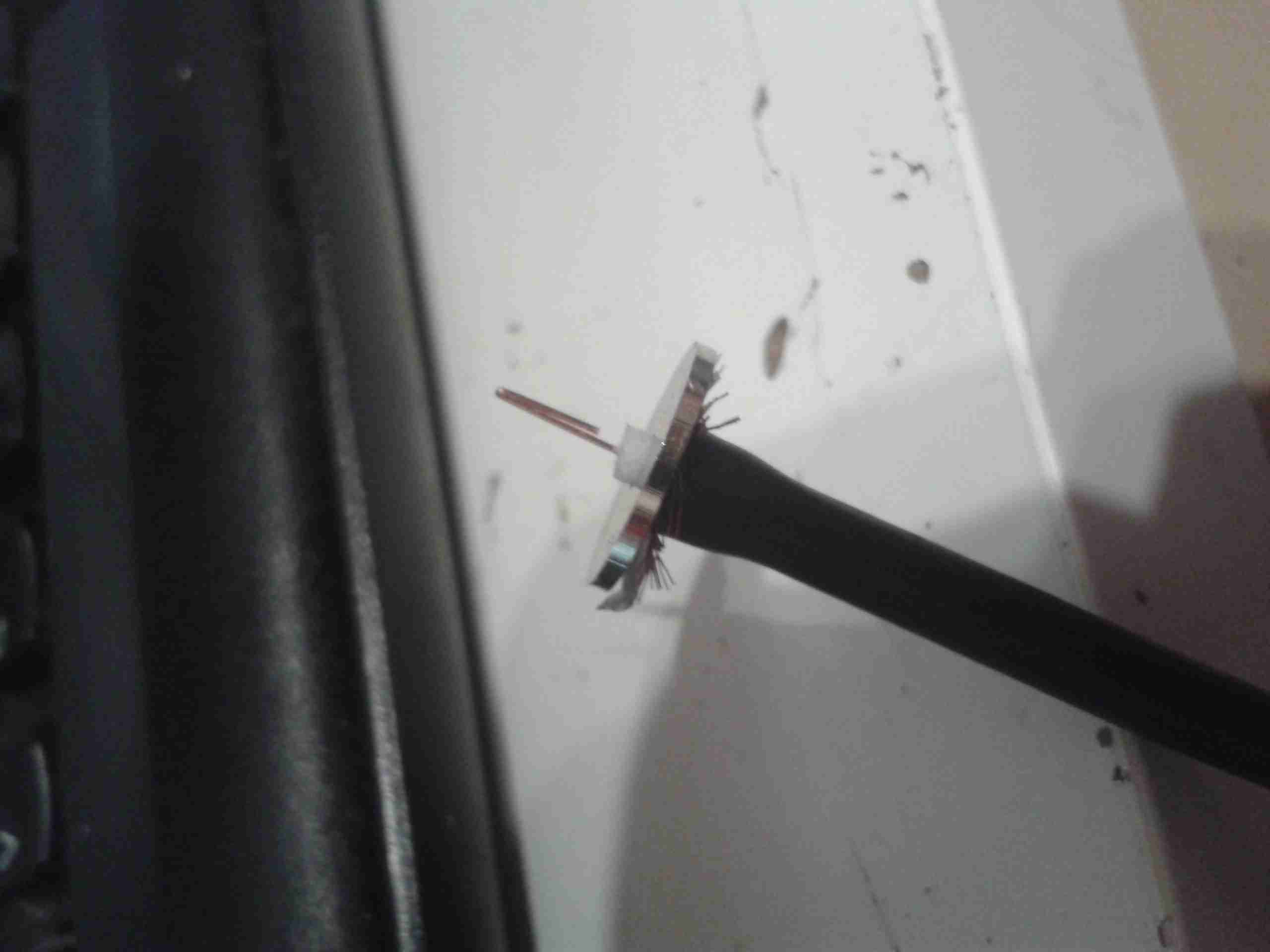
Trim the center conductor to about double the length required, to allow it to be folded over, as shown. This allows the copper to spring back against the center pin of the connector when it’s fitted, to allow a good connection.
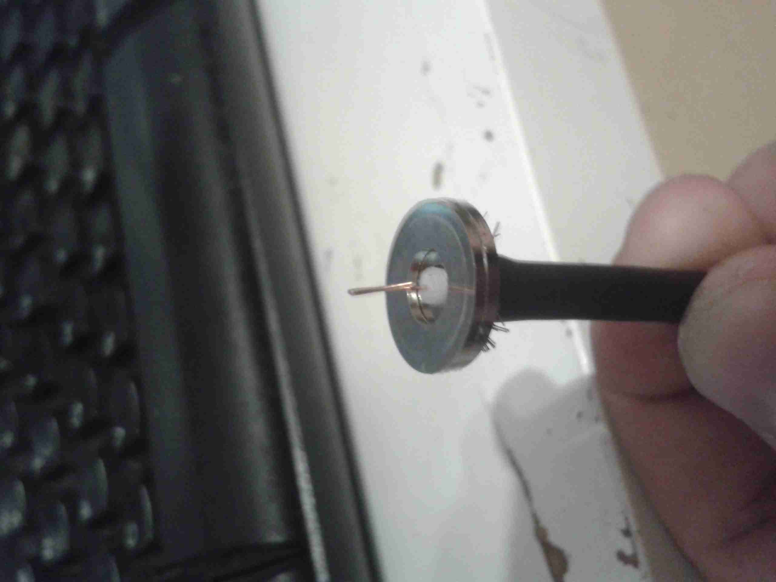
Here the final washer is fitted over the shield washer. The center insulation should be at the same level to allow the center pin to fit properly.
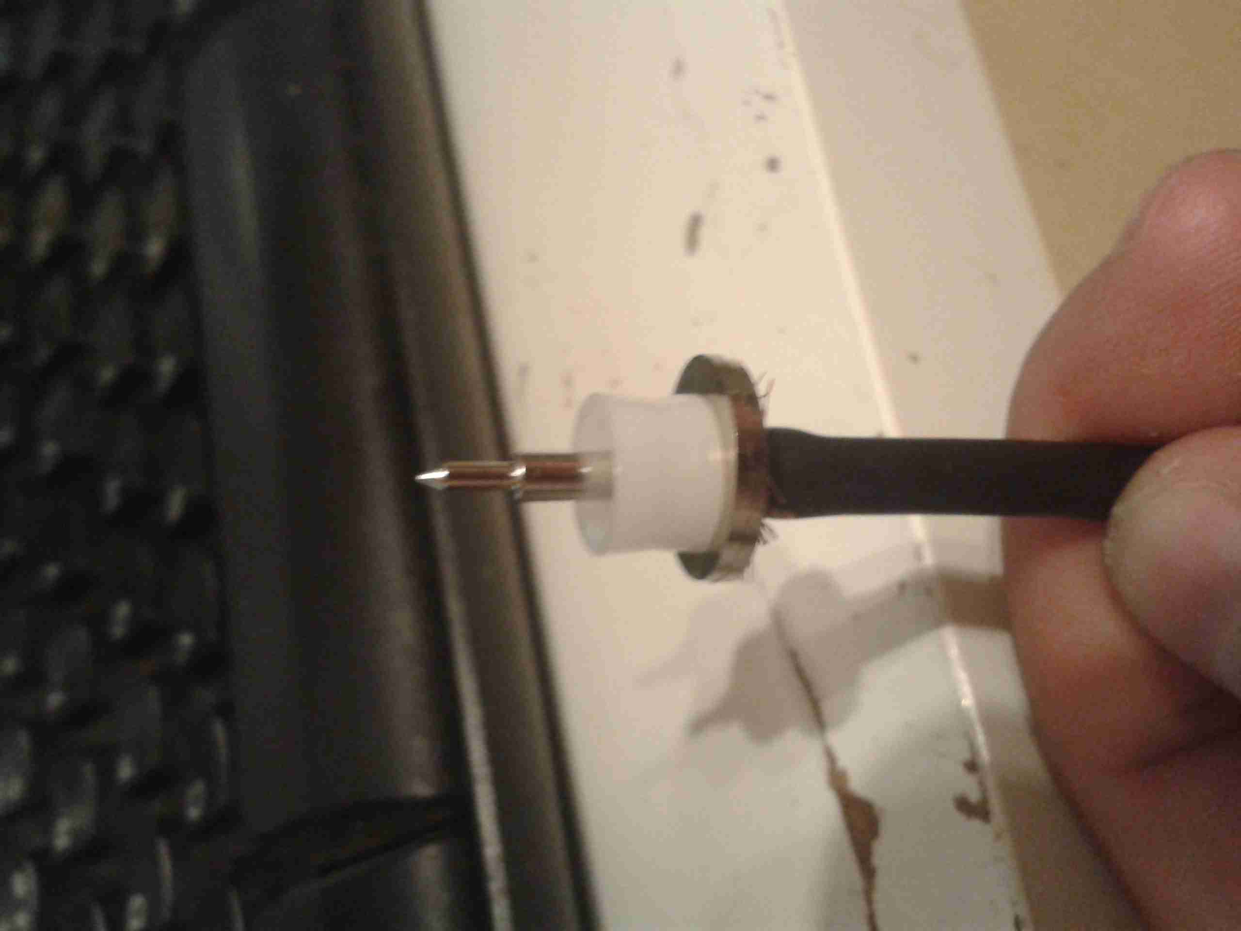
Finally, the center pin is pushed over the inner conductor of the cable, with it’s insulating spacer. Soldering these usually results in the plastic melting and a ruined connector.
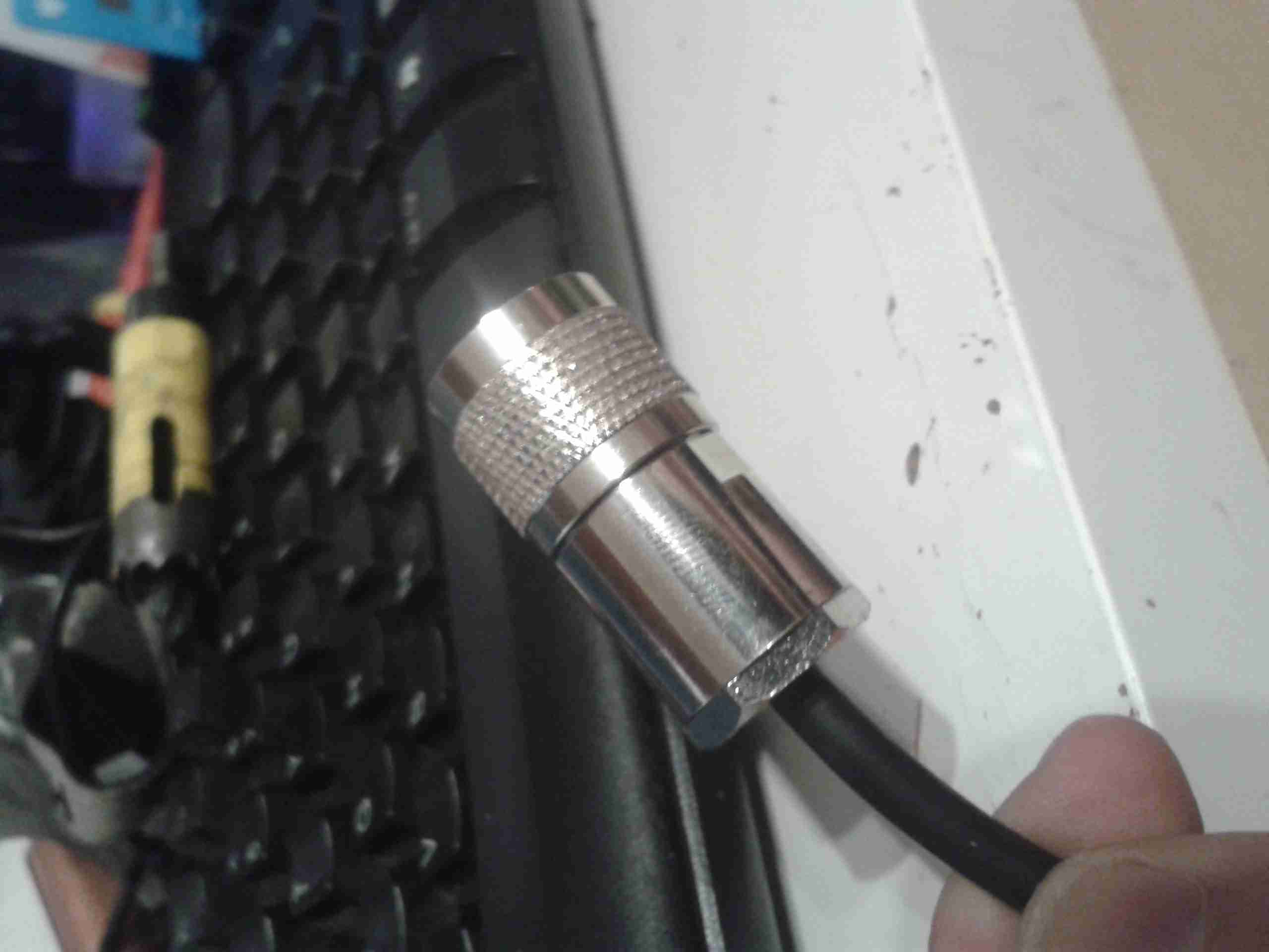
Finished plug. Make sure the backnut is tightened fully home, without twisting the connector body itself. After I’m done with the termination, I use self-amalgamating tape to form a strain relief on the cable. This prevents it from breaking at the point where it enters the backnut.
I’ve been terminating these connectors this way for a long time & have not had any issues with SWR or bad connections, dispite the fact that I don’t solder them. This also has the advantage that fewer tools are required for the job & the connectors can easily be reused should the cable wear out.
Here’s a rather unique device for protecting safes & vaults from attack by thefts.
It’s an Aritech VV602 seismic detector, based on piezoelectric sensors. Not surprisingly, this unit is covered in tamper sensors as well. There are several different sensor types in use:
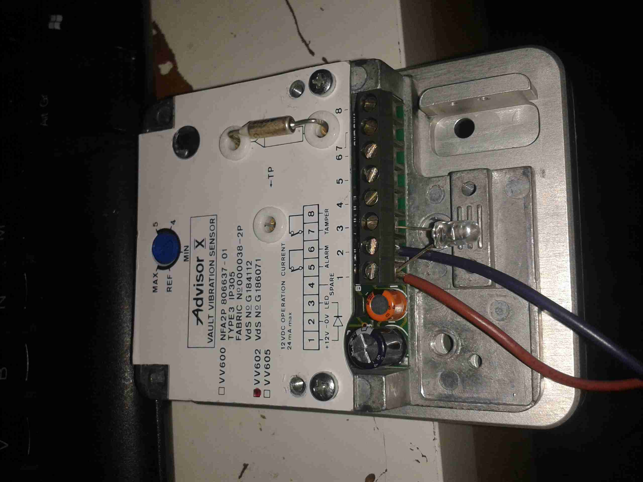
Above is the main unit, with the thermal sensor. This is just a thermal fuse, very commonly used in everything from room heaters to hairdryers. This one triggers at 84°C. The adjustment pot is also visible here.

Above is the magnetic mounting plate used to attach the device to the safe. These units are apparently mounted over the keyhole of the safe to protect the lock, so they need to be easily removable to access the safe. This is a very strong magnet & it isn’t possible to pull it from a metal object without triggering the sensor.
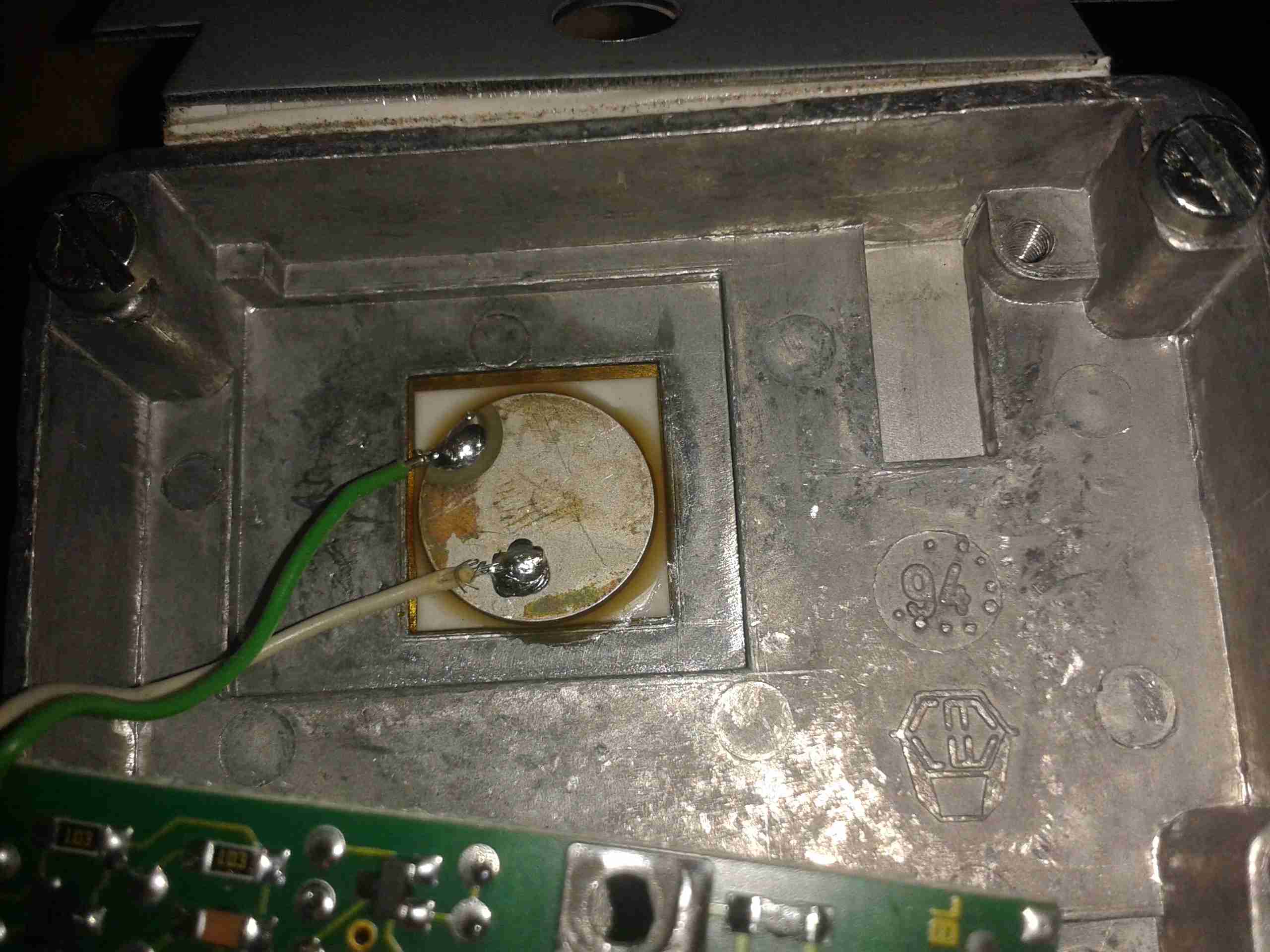
Above is the piezo vibration sensor, bonded to the backplate. When the unit receives vibration or shock, this transducer generates a voltage, which is fed to the control logic below.
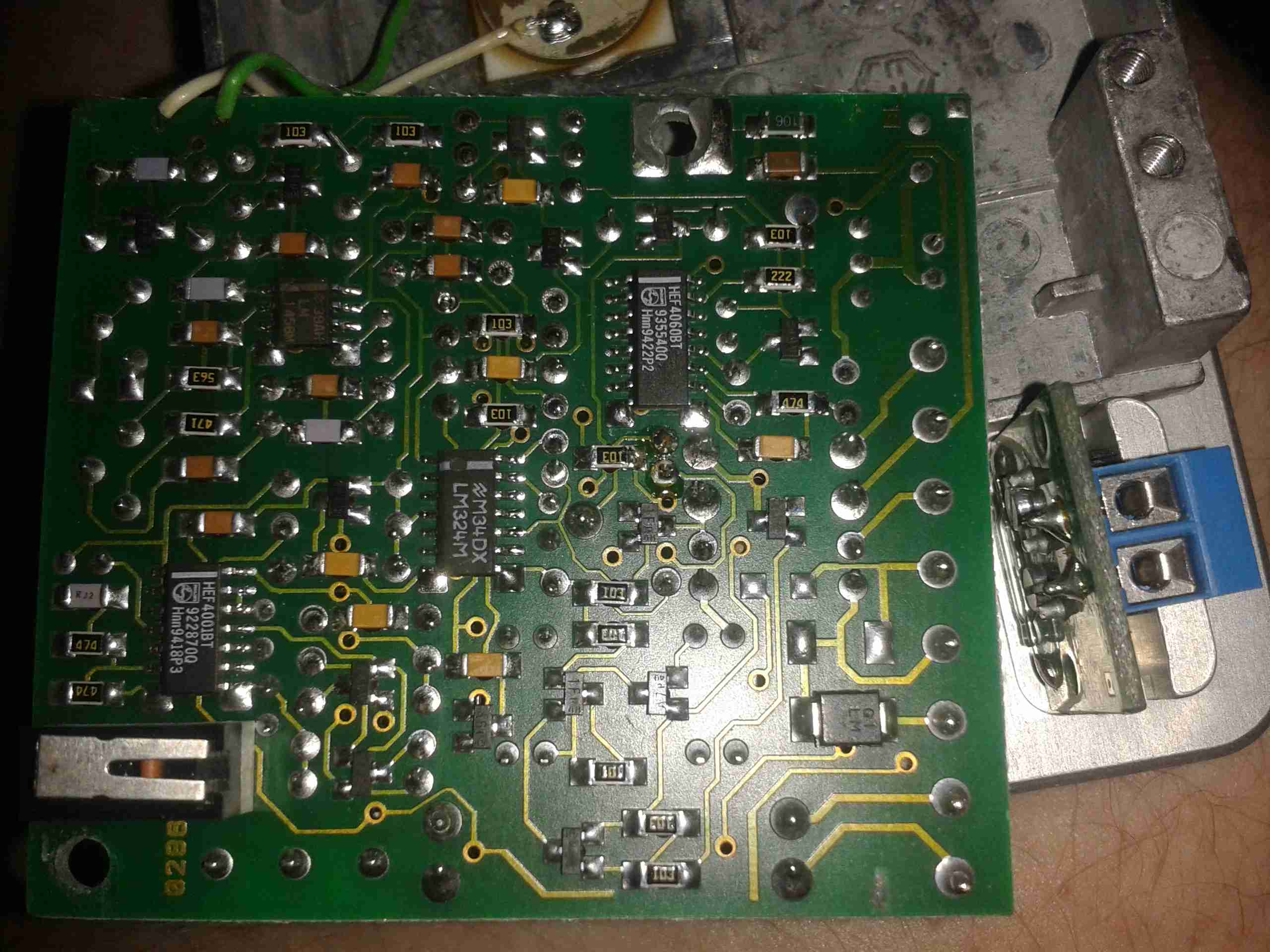
Here’s the reverse of the main PCB with the control logic ICs. These are basic logic gates, with a couple of comparators. One of the tamper switches is in the bottom left corner.
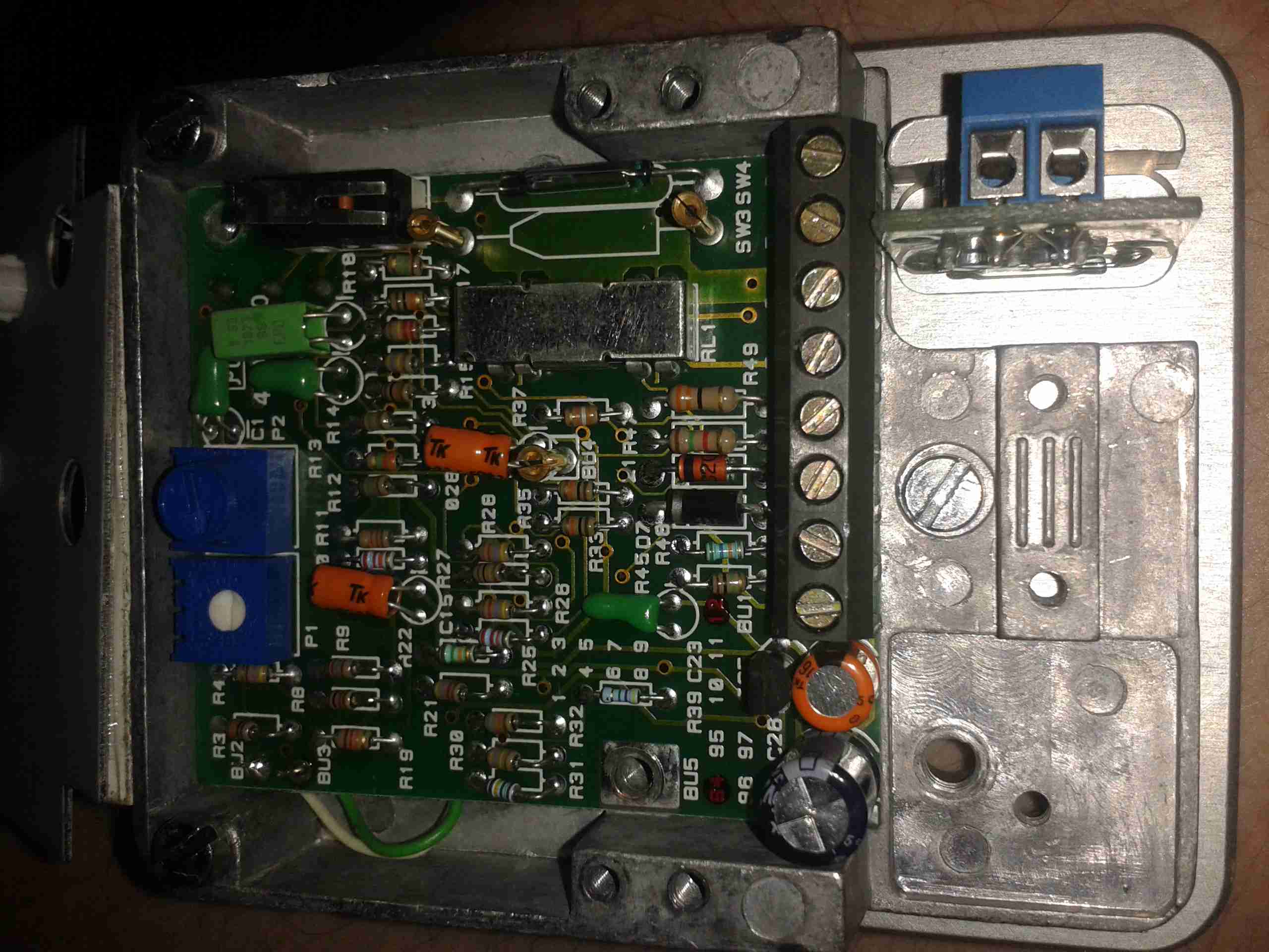
Main PCB with the connection terminals. Another tamper switch is in the top left corner, the solid-state relay is under the shield, next to the magnetic tamper switch. (Reed switch).
Some adjustment is provided for sensitivity. I’ve not found much of a difference in sensitivity though when it’s set to different levels.

Magnetic reed switch tamper on the right. Main output solid-state relay on the left under the shield.
This unit was given to me after it apparently went faulty. But on applying power it seems to work fine. Must be those experts again 😉
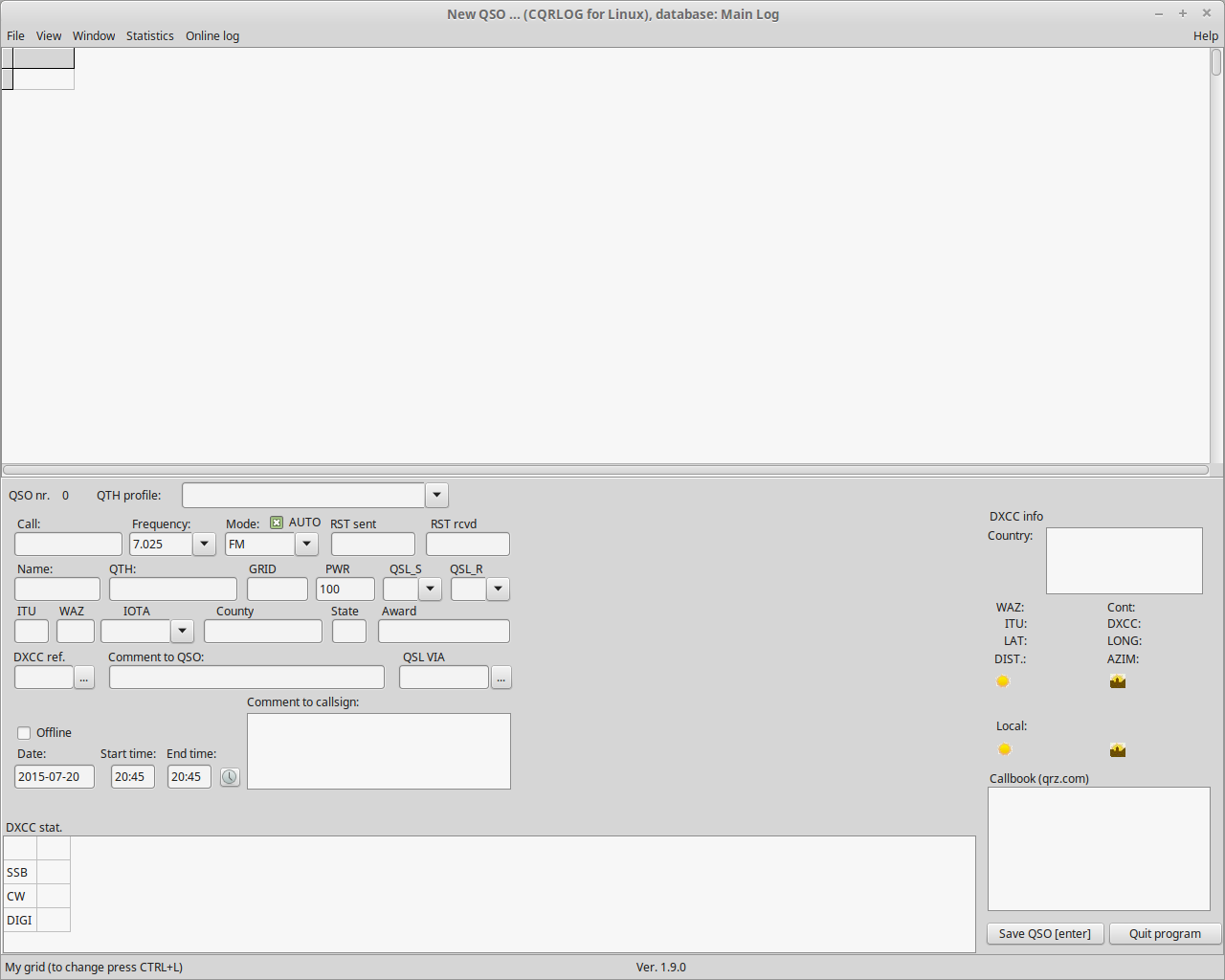
As per my site update post, I have migrated my radio log onto a new system, from CQRLOG.
CQR log has served me well since I first started in Amateur Radio, however it’s a bit complex to use, requires a backend MySQL server for it’s database, and as it’s a local application, it’s not possible to share my log with other Hams without some difficulty.
The only other major system with an online logging system is QRZ, and I find that particular site a bit of a pain, and many of the features there aren’t free. (Although it’s not horrendously expensive, I’m on a very tight budget & I must save where I can).
Because of these points, I went on a search for something that would better serve my needs. I have discovered during this search that there’s liitle out there in the self-hosted respect.
I did however find Cloudlog, a web based logging system in PHP & MySQL.
This new system allows integration with the main site, as I can run it on the same server & LAMP stack, it’s very simple to use, is visually pleasing and it even generates a Google Map view of recent QSO locations.
It will also allow me to save some resources on my main PC, running a full-blown MySQL server in the background just for a single application is resource intensive, and a bit of a waste of CPU cycles. (CQRLOG and it’s associated MySQL server is 300MB of disk space, CloudLog is 27MB).
Backups are made simpler with this system also, as it’s running on my core systems, incremental backups are taken every 3 hours, with a full system backup every 24 hours. Combined with offsite backup sync, data loss is very unlikely in any event. All this is completely automatic.
I can also take an ADIF file from Cloudlog for use with any other logging application, if the need arises.
Cloudlog is built & maintained by Peter Goodhall, 2E0SQL.
From the looks of Github, there’s also a version 2 in development, although now I have version 1 up & running, I might just stick with it, unless an easy upgrade path is available.
When I am not operating mobile, new QSOs should appear in this system almost immediately, with their respective pins on the map. (These are generated by the Grid Square location, so accuracy may vary).
If you’ve spoken to me on the air & I haven’t updated it, I’m most likely away from an internet connection, in which case your callsign will appear as soon as I have access.
73s for now folks!
Since my new Wouxun has audio output jacks, I figured it would be useful to have the ability to record what my rig hears, if anything interesting comes on the air.
Under Linux, I use an application called, (creatively enough), Audio Recorder.
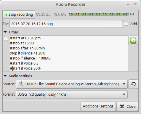
Using a simple connection to the mic input on a USB soundcard, I can capture everything the radio hears. Unfortunately this doesn’t work for outgoing audio, so it’s not much good at capture of my personal QSOs. For this I will have to set up another radio to act as the main receiver.
At some point in the future I will implement this with a Raspberry Pi as the audio capture server.
GB3MR currently has a big issue with a couple of pirates blocking use of the repeater, and while I’ve not heard anything from them in a few days, today has been much different.
I didn’t manage to get a full recording in this instance, but here’s some of the interference that’s being transmitted. In this case it sounds like there’s a licensed station or two trying to break through but not getting very far. (Sure I heard a callsign or two in there somewhere, whether they’re valid is another thing). Happy listening 🙂
Here’s a sneak preview of my next upcoming project. The target is building a monster DC-DC converter, capable of 70A continuous output, 100A surge.
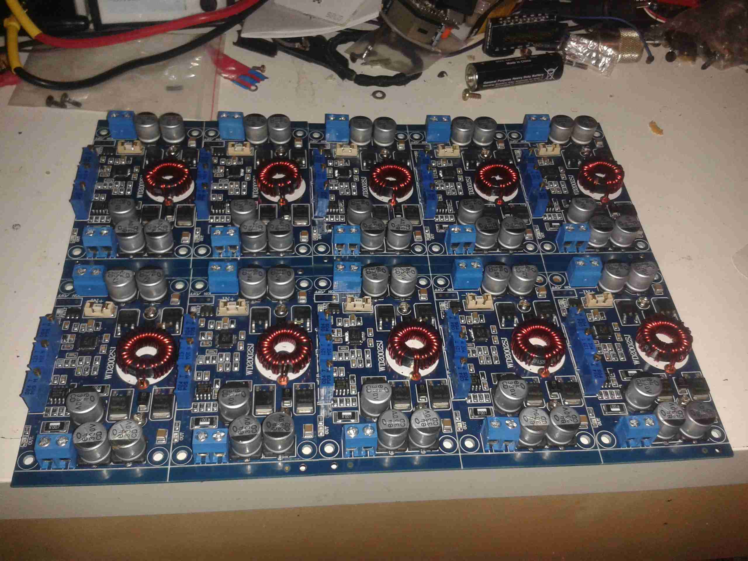
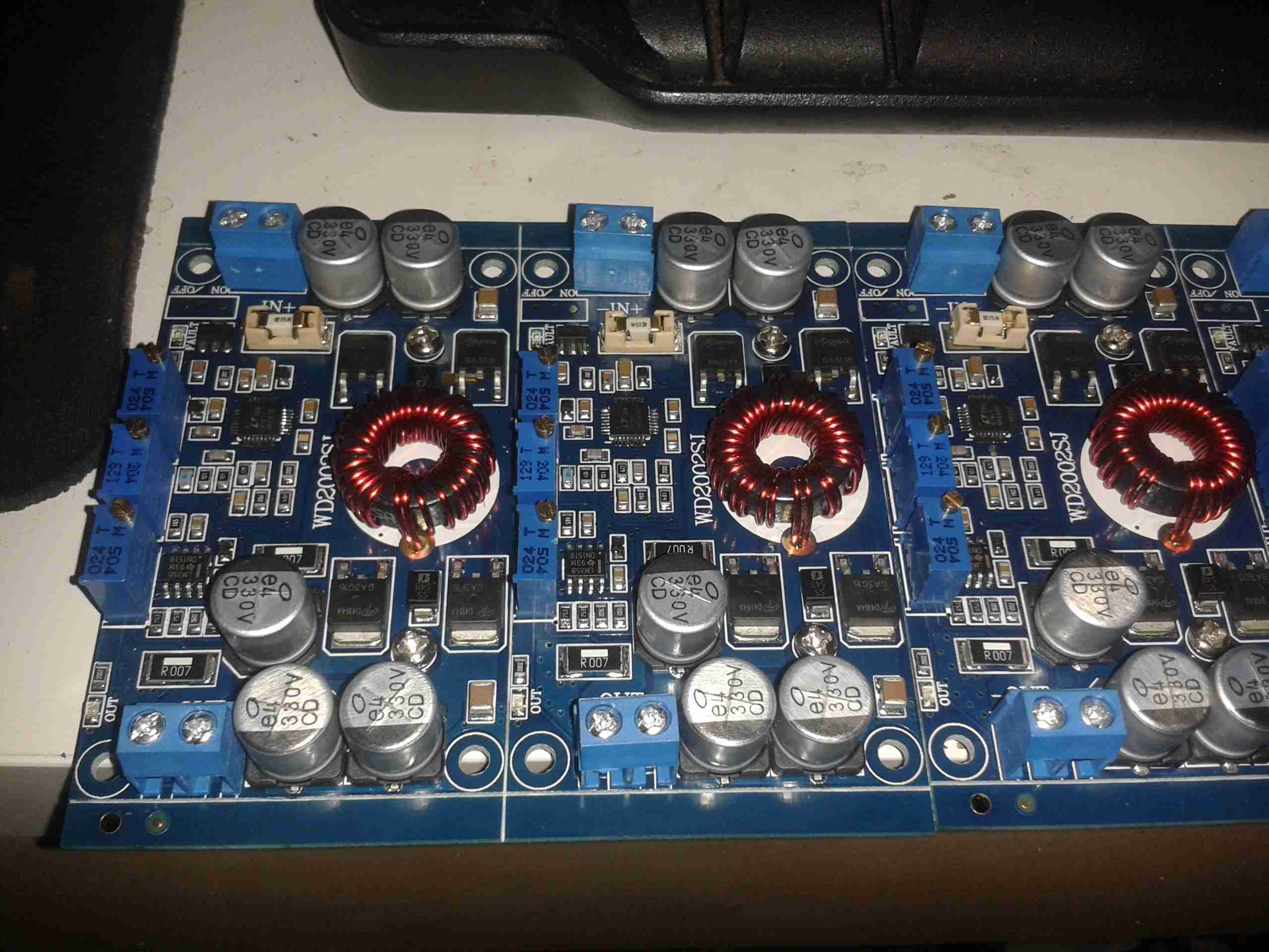
Here’s the 10 modules, each rated at up to 7A continuous & 10A surge. I ordered so many that they turned up still panelised!
After a few years of running with the same look, I’ve decided on some changes.
Finally there have been some behind the scenes changes to implement some better security on site.
Getting the number of hits I do per day, this site gets attacked by the Internet’s Great Unwashed on a regular basis. No attack has ever been successful but more security never hurts!
73s folks!