I recently used a Vishay Spectrol Precision 10-turn potentiometer in my latest PSU project, and since these clip together instead of being ultrasonically welded like Bourns potentiometers, I decided to do a quick teardown for the blog. I didn’t find much in the way of how these pots worked from a search, so here we go!
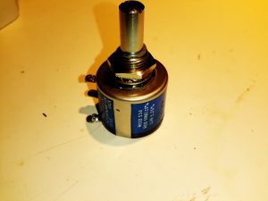
Here’s a pot of the same spec as I used in the previous project, again from my random used junk bin. This is a 100Ω, 5% wirewound potentiometer. The shaft is secured in the centre bushing with a snap ring, this is easily removed with a pair of needlenose pliers.
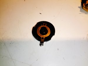
After unclipping the back cover, the stationary part of the wiper contact is visible in the back plastic cover.
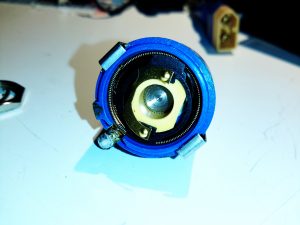
Inside the back of the potentiometer shows the inner workings. These devices have a large helical winding of resistance wire around the inner diameter of the casing, the wiper tracks this helix as the potentiometer is turned.
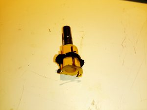
As the wiper must move axially as it winds around the spiral of resistance wire, the contact is mounted on a pair of guides so it can slide back & forth. The electrical connection is made via another spring contact that runs down the side of the plastic shaft insert. Two notches cut into the black plastic wiper frame engage with the round profile of the resistance winding like a screw into a nut, keeping the wiper in perfect alignment as it travels the full length of the winding. I suspect all these moving contacts are made of Beryllium Copper in this rather expensive component as this alloy is very flexible, as well as being a very good electrical conductor.
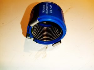
With the centre shaft & it’s wiper contact removed from the shell, the helix of resistance wire can be seen inside. Oddly, the former the resistance wire is wound around appears to be metal, possibly copper, but to keep the entire thing from shorting itself out this must be coated in insulation.
