Posted on 10 Comments

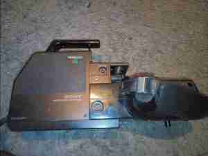
Sony HVC-3000P Trinicon Camera Teardown

Camera Left
Camera Left

Following on from the viewfinder teardown, here’s the rest of the camera. This unit dates back to 1980, and is made almost exclusively of cast aluminium. Very little plastic has been used here & only for the bits that the user comes into contact with. This camera is based around the Sony Trinicon camera tube system, technology dating back before CCDs. There aren’t many controls on this side of the camera, only the record button, which is hidden behind the camera handgrip.
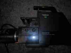
Camera Right
Camera Right

The other side of the camera has most of the controls for the picture.
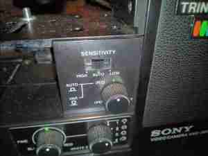
Image Controls
Image Controls

The image controls inclue auto / manual iris, white balance & colour balance.
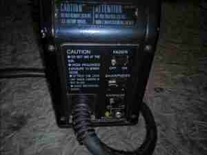
Rear Panel
Rear Panel

Sharpness & fader controls are on the back of the camera, along with the umbilical cable which would have connected to a Betamax recorder.
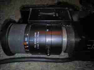
Main Lens
Main Lens

The lens on this camera is massive, at least a kilo of optical glass. Focus control is manual, with both auto & manual zoom control.
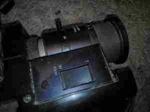
Lens Zoom Control
Lens Zoom Control

The Zoom controls are on top of the grip, with a button to the rear of the control which I have no idea about. The internal belts are a bit rotted with age so the zoom function doesn’t work great.
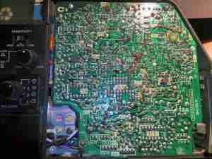
Trinicon Control Board

After removing the side covers, the two large PCBs become visible. These units are absolutely packed with electronics. On this side is the Trinicon tube control board, generating all the high voltages for electron beam acceleration, focus & electrostatic deflection of the beam. There’s around 500 volts knocking around on this board, with some rather specialised hybrid modules doing all the high voltage magic.
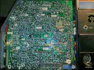
Video Process Board
Video Process Board

The other side of the camera has the video process board, which performs all the colour separation of the video signal from the tube, processes the resulting signals into a composite video signal, and finally sends it down the umbilical.
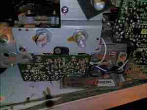
Bare Controls
Bare Controls

Removing some of the remaining covers exposes the bare video controls, and a small PCB just underneath covered in trimpots to set factory levels.
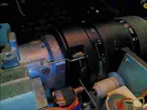
White Balance Filter Arm

The white balance is partially electronic & partially mechanical. This lever actuates a filter inside the lens assrembly.
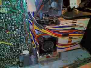
Remote Connector
Remote Connector

A DIN connector offers remote control ability. The large loom of wires disappearing off to the right is dealing with the zoom mechanism & the onboard microphone amplifier. Just under the DIN connector hides the system power supply, inside a soldered can. The can under the white tape is the head end amplifier for the Trinicon video tube.
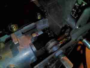
Trinicon Mount
Trinicon Mount

Hiding in the centre of the camera inside the casting is the Trinicon tube assembly itself. The label can just be seen here.
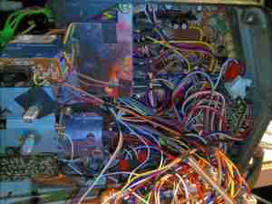
Camera Internals 1
Camera Internals 1

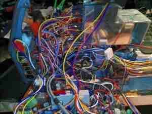
As is typical of 1980’s electronic design, the main boards swing down & are designed to slot into the base casting folded out for repairs. Internally the unit is a rat’s nest of wiring loom. There’s also another shielding can in here nestled between the boards – this is the video sync generator circuit.
Camera Internals 2
Camera Internals 2

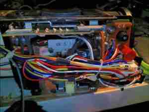
The other side gives a better view of the video sync generator can. I’ll dive into the individual modules later on.
Lens Zoom Assembly
Lens Zoom Assembly

Under the remaining side cover is the zoom assembly & microphone amplifier board. More massive wiring loom hides within.
Video Sync Generator

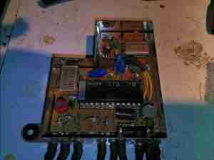
The video sync generator is pretty sparse inside, just a large Sony CX773 Sync Generator IC, with a pair of crystals. There are a couple of adjustments in here for video sync frequencies.
Head End Amplifier
Head End Amplifier

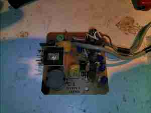
Removed from it’s shielding can, here is the head end amplifier for the Trinicon tube. This very sensitive JFET input amplifier feeds into the main video process board.
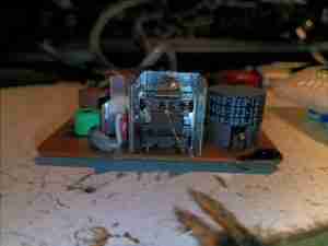
Input Transformer
Input Transformer

The Trinicon tube target connects to this input transformer on the front of the amplifier board.
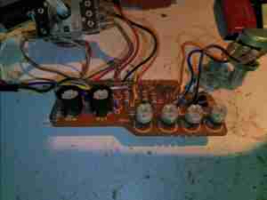
Internal Video Adjustments

The internal white balance controls are on this small PCB, mounted under the user-accessible controls.
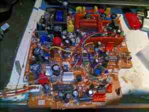
Vidicon Control Board

Here’s the main control board responsible for the Trinicon tube & exposure control. Down near the front is the auto-iris circuit, nearer the centre is timing control & at the top is the high voltage power supply & deflection generator ICs.
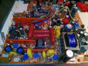
High Voltage Section

Here’s the high voltage section, the main transformer at right generating the voltages required to drive the video tube. The large orange hybrids here are a pair of BX369 high-voltage sawtooth generators that create the deflection waveforms for the tube. The other large hybrid is a BX382 Fader Control.
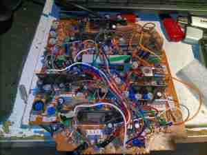
Video Process Board
Video Process Board

The other large board contains all the video process circuitry, all analogue of course. There are a lot of manual adjustment pots on this board.
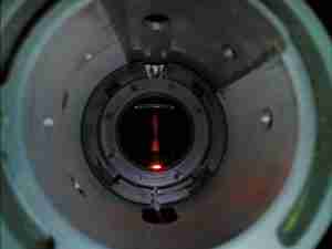
Lens Barrel
Lens Barrel

After removing the lens assembly, the tube assembly is visible inside the barrel casting. Not much to see yet, just the IR filter assembly.
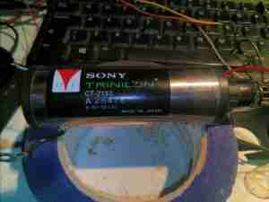
Trinicon Tube Assembly

Here’s the unit removed from the camera. Unfortunately this tube is dead – it shows a lot of target burn on the resulting image, and very bad ghosting on what poor image there is. The Trinicon tube itself is encased in the focus coil assembly, the windings of which are hidden under the shielding.
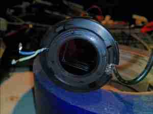
IR Filter
IR Filter

The IR filter is locked into the front of the tube, on a bayonet fitting. The twin target wires are running off to the left, where they would connect to the head end amplifier.
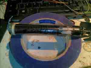
Bare Tube
Bare Tube

After removing the IR filter glass, the Trinicon tube itself is removed from the focus coil assembly. There’s an electron gun at the rear of the tube, like all CRTs, although this one works in reverse – sensing an image projected on the front instead of generating one.
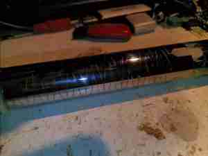
Deflection Plates
Deflection Plates

It’s a little difficult to see, but the electrostatic deflection electrodes in this tube are created from the aluminium flashing on the inside of the glass, in a zig-zag pattern. The interleaving electrodes are connected to base pins by spring contacts at the electron gun end of the tube.
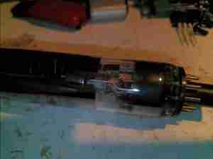
Electron Gun
Electron Gun

The electron gun is mostly hidden by the getter flash & the deflection electrodes, but the cathode can is visible through the glass, along with the spring contacts that make a connection to the deflection electrodes. This is also a very short gun – it doesn’t extend more than about 5mm into the deflection zone. The rest of the tube up to the target is empty space.
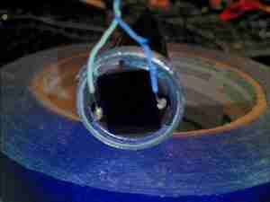
Target
Target

Finally, here’s the target end of the tube. I’m not sure how the wires are attached to the terminals – it certainly isn’t solder, maybe conductive adhesive?
It uses a vertically striped RGB colour filter over the faceplate of an otherwise standard Vidicon imaging tube to segment the scan into corresponding red, green and blue segments. It is used mostly in low-end consumer cameras, though Sony also used it in some moderate cost professional cameras in the 1980s.
Although the idea of using colour stripe filters over the target was not new, the Trinicon was the only tube to use the primary RGB colours. This necessitated an additional electrode buried in the target to detect where the scanning electron beam was relative to the stripe filter. Previous colour stripe systems had used colours where the colour circuitry was able to separate the colours purely from the relative amplitudes of the signals. As a result, the Trinicon featured a larger dynamic range of operation.

I have the service manuals below for the HVP-2000P & the HVP-4000P, which are very similar cameras, so these may be useful to anyone who has one of these!
Viewing Spectral Lines in Discharge, Other Colours in Output

For accurate measurements, you’ll need an optical instrument such as a monochromator or spectrophotometer or optical spectrum analyzer. But to simply see the complexity of the discharge spectrum inside the bore of a He-Ne laser tube, it’s much easier and cheaper.

(Spectra for various elements and compounds can be easily found by searching the Web. The NIST Atomic Spectra Database has an applet which will generate a table or plot of more spectral lines than you could ever want.)

Instant Spectroscope for Viewing Lines in He-Ne Discharge

It is easy to look at the major visible lines. All it takes is a diffraction grating or prism. I made my instant spectroscope from the diffraction grating out of some sort of special effects glasses – found in a box of cereal, no less! – and a monocular (actually 1/2 of a pair of binoculars).

  • If you missed the Kellogg’s option, diffraction gratings can be purchased from places like Edmund Scientific. You don’t need anything fancy – any of the inexpensive ‘transmission replica gratings’ on a flat rigid substrate or mounted between a pair of plane glass plates will be fine. In a pinch, a CD disc or other optical media will work but only as a reflection grating so mounting may be a problem. A spectroscope can also be made with a prism of course but a diffraction grating is likely to be less expensive and better for this application since it is much lighter and easier to mount.
  • The plasma tube of a bare He-Ne laser is an ideal light source since it provides its own slit as the glow discharge is confined to the long narrow capillary bore. However, this approach can also be used with other lasers as long as the beam can be focused to a spot on a wall or screen. This will produce a ‘bright spot spectra’ instead of politically correct lines but you can’t have everything. 🙂
  • The diffraction grating can be used by itself but the additional optics will provide magnification and other benefits for people with less than perfect eyeballs.
  • Glue the diffraction grating to a cardboard sleeve that can be slipped over the (or one) objective of a monocular, binocular, or small telescope – or the telephoto lens of your camera. Orient it so that the dispersion will be vertical (since your slit will be horizontal).
  • Operate the HeNe tube on a piece of black velvet or paper. This will result in optimum contrast. This is best done in a darkened room where the only source of light is the laser tube itself. Just don’t trip and zap yourself on the high voltage!
  • A diffraction grating produces several images. The zero’th order will be the original image seen straight ahead. The important ones are the first order spectra. Tip the instrument up or down to see these. The dispersion direction – order of the colours – will depend on which way it is tipped.
  • Any distance beyond the closest focus of your instrument will work but being further away will reduce the effective width of the ‘slit’ resulting in the ability to distinguish more closely spaced lines.

The shear number of individual spectral lines present in the discharge is quite amazing. You will see the major red, orange, yellow, and green lines as well as some far into the blue and violet portions of the spectrum and toward the IR as well.

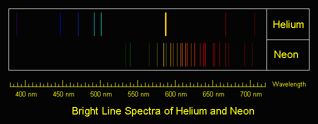
Bright Line Spectra of Helium and Neon

All of those shown will be present as well as many others not produced by the individual gas discharges. There are numerous IR lines as well but, of course, these will not be visible.

Place a white card in the exit beam and note where the single red output line of the He-Ne tube falls relative to the position and intensity of the numerous red lines present in the gas discharge.

As an aside, you may also note a weak blue/green haze surrounding the intense main red beam (not even with the spectroscope). This is due to the blue/green (incoherent) spectral lines in the discharge being able to pass through the output mirror which has been optimized to reflect well (>99 percent) at 632.8 nm and is relatively transparent at wavelengths some distance away from these (shorter and longer but you would need an IR sensor to see the longer ones). Since it is not part of the lasing process, this light diverges rapidly and is therefore only visible close to the tube’s output mirror.

Dynamic Measurement of Discharge Spectra

The following is trivial to do if you have a recording spectrometer and external mirror He-Ne laser. For an internal mirror He-Ne laser tube, it should be possible to rock one of the mirrors far enough to kill lasing without permanently changing alignment. If you don’t have proper measuring instruments, don’t worry, this is probably in the “Gee wiz, that’s neat but of marginal practical use” department. 🙂

(From: George Werner (glwerner@sprynet.com).)

Here is an effect I found many years ago and I don’t know if anyone has pursued it further.

We had a recording spectrometer in our lab which we used to examine the incoherent light coming from the laser discharge. This spectrum when lasing was slightly different from the spectrum when not lasing, which one can expect since energy levels are redistributed. As with most detectors, ours used a chopper in the spectrometer light beam and a lock-in amplifier.

Instead of putting the chopper in the path of light going to the spectrometer, I put it in the path of the internal laser beam, so that instead of an open/closed signal going to the amplifier it was a lasing/not-lasing signal. What was recorded then was three kinds of spectrum lines: some deflected positive in the normal way, others deflected negative, and the third group were those that were unaffected by chopping, in which case when we passed over the line we only saw an increase in the noise level. Setting up such a test is easy. The hard part is interpreting the data in a meaningful way.

Other Colour Lines in Red He-Ne Laser Output

When viewing spectral lines in the actual beam of a red He-Ne laser, you may notice some very faint ones far removed from the dominant 632.8 nm line we all know and love. (This, of course, also applies to other colour He-Ne lasers.)

For He-Ne lasers, the primary line (usually 632.8 nm) is extremely narrow and effectively a singularity given any instrumentation you are likely to have at your disposal. Any other lines you detect in the output are almost certainly from two possible sources but neither is actual laser emission:

  • Plasma discharge – there are many strong emission lines in the actual discharge – and none of them are actually at the 632.8nm lasing wavelength! These extend from the mid-IR through the violet.Close to the output mirror, you may see some of this light seeping through especially at wavelengths in the green, blue, and violet, for which the dielectric mirrors are nearly perfectly transparent. However, such light will be quite divergent and diffuse and won’t be visible at all more than a couple of inches from the mirror.
  • Superradiance – As we know, He-Ne lasers can be made to operate at a variety of wavelengths other than the common 632.8nm red. The physics for these is still applicable in a red He-Ne tube but the mirrors do not have the needed reflectivity at these other wavelengths and therefore the resonator gain is too low to support true laser action. However, stimulated emission can still take place in superradiance mode – one pass down the tube and out, exiting easily for the green wavelength in particular since the dielectric mirrors are quite transparent in that region of the spectrum.The result will be a weak green beam that can sometimes be observed with a spectroscope in a very dark room room. It isn’t really quite as coherent or monochromatic as the beam from a true green He-Ne laser and probably has much wider divergence but nonetheless may be present. It may be easier to see this by using your spectroscope to view the bright spot from the laser on a white card rather than by deflecting the beam and trying to locate the green dot off to one side.Note: I have not been able to detect this effect on the short He-Ne tubes I have checked.

Since the brightness of the discharge and superradiance output should be about the same from either mirror, using the non-output end (high reflector) should prove easier (assuming it isn’t painted over or otherwise covered) since the red beam exiting from this mirror will be much less intense and won’t obscure the weak green beam.

Note that argon and krypton ion lasers are often designed for multiline output where all colours are coherent and within an order of magnitude of being equal to each other in intensity or with a knob to select an individual wavelength. Anything like this is only rarely done with He-Ne lasers because it is very difficult (and expensive) due to the low gain of the non-red lines.

Posted on Leave a comment

Huawei E160E USB HSDPA Modem

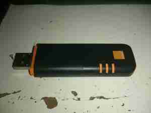
E160E Modem
Huawei E160E Modem

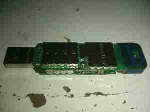
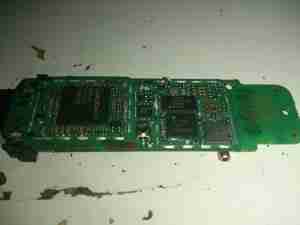
Here’s an old HDSPA 3G USB modem stick that I got with a mobile phone contact many years ago. As it’s now very old tech, and I have a faster modem, not to mention that I’m no longer with Orange (Robbing <expletive>), here’s a teardown of the device!

Cover Removed
Cover Removed

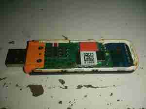
The top shell is just clipped into place, while a pair of very small screws hold down the orange piece at left to hold the PCB stack in the casing. Not much to see here, but it’s clear that there’s a lot crammed into a very small space.

PCB Assembly
PCB Assembly

Here’s the PCB stack removed from the outer casing. The main antenna is on the right, attached with another small screw. Every IC on the boards is covered with an RF can. No problems there, pliers to the rescue!

SD Card Slot
SD Card Slot

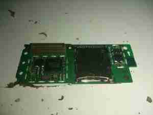
Here’s the top PCB, all the shields have been removed. On the left is a Qualcomm PM6658 Power Management IC with integrated USB transceiver. This is surrounded by many of the power management circuits.
The integrated SD Card slot is on the right side. with what looks to be a local switching regulator for supply voltage. This might also provide the SIM card with it’s power supply.

PSU & SIM Contacts
PSU & SIM Contacts

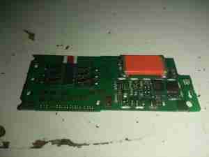
The other side of the top board reveals more power management, with another switching regulator, and a truly massive capacitor at the top edge. I’m guessing this is a solid Tantalum.

Main Chipset PCB
Main Chipset PCB

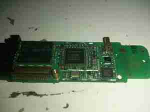
The other PCB holds the main chipset & RF circuits. On the left here is a Samsung MCP K5D1G13ACH IC. This one is a multiple chip package, having 1Gbit of NAND Flash & 512Mbit of mobile SDRAM.
To it’s right is a Qualcomm RTR6285 RF Transceiver. This IC supports multiband GSM/EDGE/UMTS frequencies & also has a GPS receive amplifier included.
At bottom right is an Avago ACPM7371 Wide-Band 4×4 CDMA Power Amplifier. The external antenna connector is top right.

Main Chipset PCB Reverse

On the other side of the main PCB is a Qualcomm MSM6246 Baseband processor. Not sure about this one as I can’t find anything resembling a datasheet. Another micro-coax connector is in the centre, probably for factory test purposes, as it’s not accessible from the outside.
Just above the coax connector is a Qorvo RF1450 SP4T (single-pole 4-throw) High Power (34.5dBm) GSM RF Switch.
Upper right is an Avago FEM-7780 UMTS2100 4×7 Front End Module.
Under that is an RFMD RF3163 Quad-Band RF Power Amplifier Module.

Posted on 1 Comment

12v Temperature Controlled Soldering Iron

In my shack, 99% of my gear is all 12v powered, which is good for a few reasons:

  • Single Power Supply – This increases efficiency, as I’m only getting the losses of a single supply.
  • Safety – Mains voltages are dangerous, I’m not fond of working on such equipment.
  • Portability – I can power everything pretty much no matter were I am from a convenient car battery.
  • Convenience – Since everything is single supply, with all the same plugs, I don’t have to think about what goes where. This is more important due to my forgetfulness ;).

The one piece of equipment I regularly use that isn’t 12v is my soldering station. This is a Maplin A55KJ digital unit, which uses a 24v heating element.
While the soldering wand works OK when hooked direct to a 12v power supply (only at half power though), this removes the convenience of having temperature control.

The circuitry inside the unit is PIC microcontroller based, and doesn’t even bother rectifying the AC from the supply transformer before it’s sent to the heater. Because of this there are several reasons why I can’t just hook a DC-DC converter up to it to give it 24v.

It’s sensing the zero-crossing for the triac switch, to reduce heat dissipation, so it refuses to work at all with DC.

On looking at the Great Google, I found a project on Dangerous Prototypes, an Arduino based PID controller for soldering irons.

This requires that the soldering wand itself contains a thermocouple sensor – as the Maplin one I have is a cheap copy of the Atten 938D, it doesn’t actually use a thermocouple for temperature sensing. It appears to read the resistance of the element itself – Nichrome heating elements change resistance significantly depending on temperature.

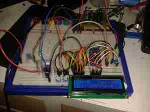
I’ve managed to find a source of cheap irons on eBay, with built in thermocouples, so I’ve got a couple on order to do some testing with. While I wait for those to arrive, I’ve prototyped up the circuit on breadboard for testing:

Prototype
Prototype

I’ve remapped some of the Arduino pins, to make PCB layout less of a headache, but the system is working OK so far, with manual input for the sensed temperature.
I’m using an IRL520N logic-level HEXFET for the power switching, rated at 10A. As the irons only draw a max of 4.5A, this is plenty beefy enough.
To come up with the +24v supply for the heater, a small DC-DC converter will be used.

More to come when the components for the thermocouple amplifier arrive, and the soldering irons themselves!

Posted on Leave a comment

Labgear PSM114E/S 12v Conversion

Onboard the boat we have a small issue with a weak TV signal, and this coupled with a 60′ long run of coax is an issue. Due to the loss in the coax, we’ve lost most of the already weak signal.
To try & solve this issue, I’m fitting a masthead amplifier unit.

These amplifiers are fed power down the same coax that’s carrying the RF signal, and a special power supply is supplied with the amplifier for this. However it’s only 240v AC, no 12v version available.

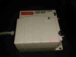
Here’s the power supply unit, which fits into the coax between the TV & the antenna.

Amplifier Supply
Amplifier Supply

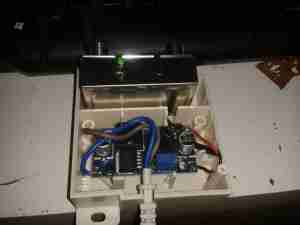
Luckily the 240v supply is easily removable & here has been replaced with a 12v regulator.

New Supply
New Supply

There’s not very much inside the shielding can, just a few filter capacitors & an RF choke on the DC feed, to keep the RF out of the power supply system.

The original cable is used, so the supply doesn’t even look like it’s been modified from the outside.

More to come on this when I get the amplifier installed along with the new coax run 🙂

73s

Posted on 4 Comments

AD9850 DDS VFO PCB & Schematic Layout

I recently came across a design for an Arduino controlled AD9850 DDS module, created by AD7C, so I figured I would release my Eagle CAD design for the PCB here.

It is a mainly single-sided layout, only a few links on the top side are needed so this is easy to etch with the toner transfer method.

My version uses an Arduino Pro Mini, as the modular format is much easier to work with than a bare ATMega 328.

RF output is via a SMA connector & has a built in amplifier to compensate for the low level generated by the DDS Module.

DDS VFO
DDS VFO

Version 2 Update: Added reverse polarity protection, added power indicator LED, beefed up tracks around the DC Jack.
[download id=”5571″]

Posted on Leave a comment

DIY Valve Amplifier – Part 1 – Amplifier Section

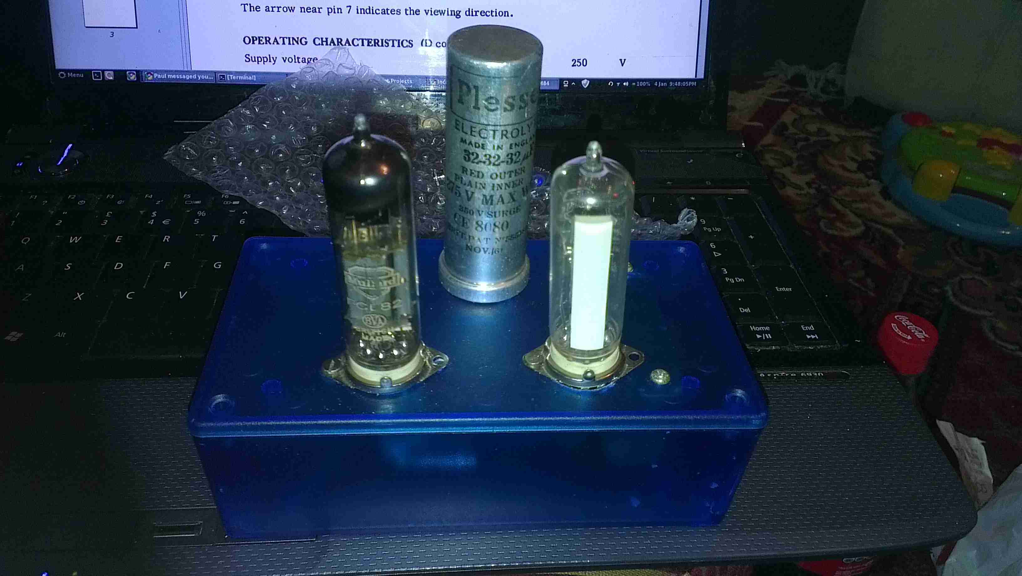
Components
Components

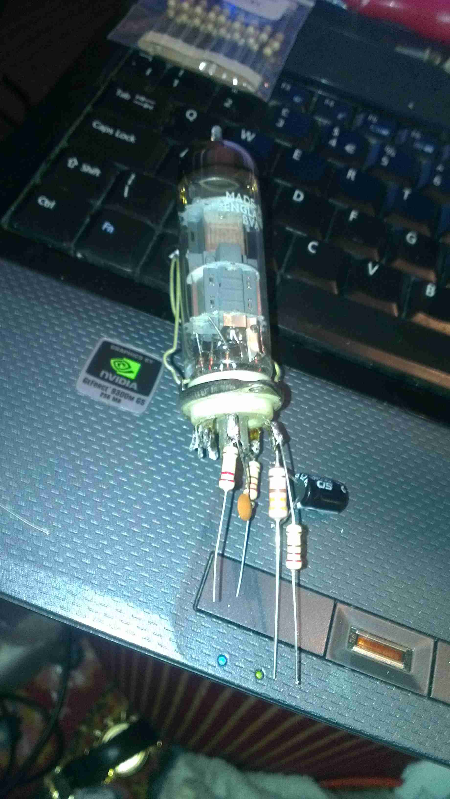
Here are a few details of a valve amplifier I am building, using the valve related parts from a 1960’s reel to reel tape recorder.

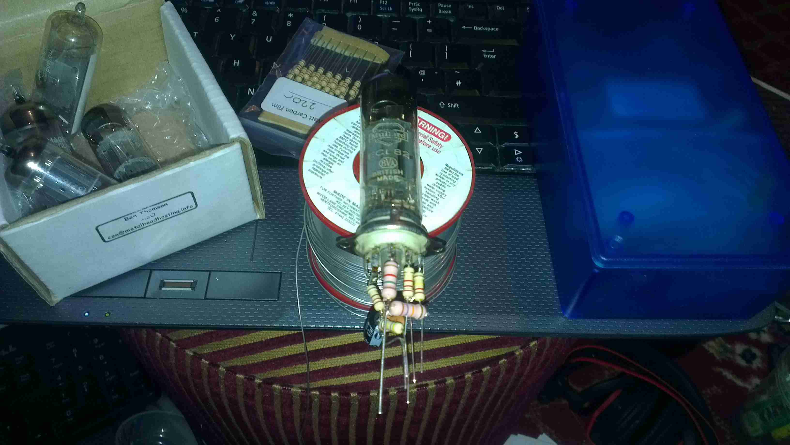
This amplifier is based on an a Mullard ECL82 triode/pentode valve, with an EM84 magic eye tube for level indication.

Beginnings Of The Amplifier

Here the first components are being soldered to the tags on the valve holder, there are so few components that a PCB is not required, everything can be rats-nested onto the valve holders.

Progress
Progress

Progressing with the amplifier section componentry, all resistors are either 1/2W or 2W.

Valve Sockets Fitted

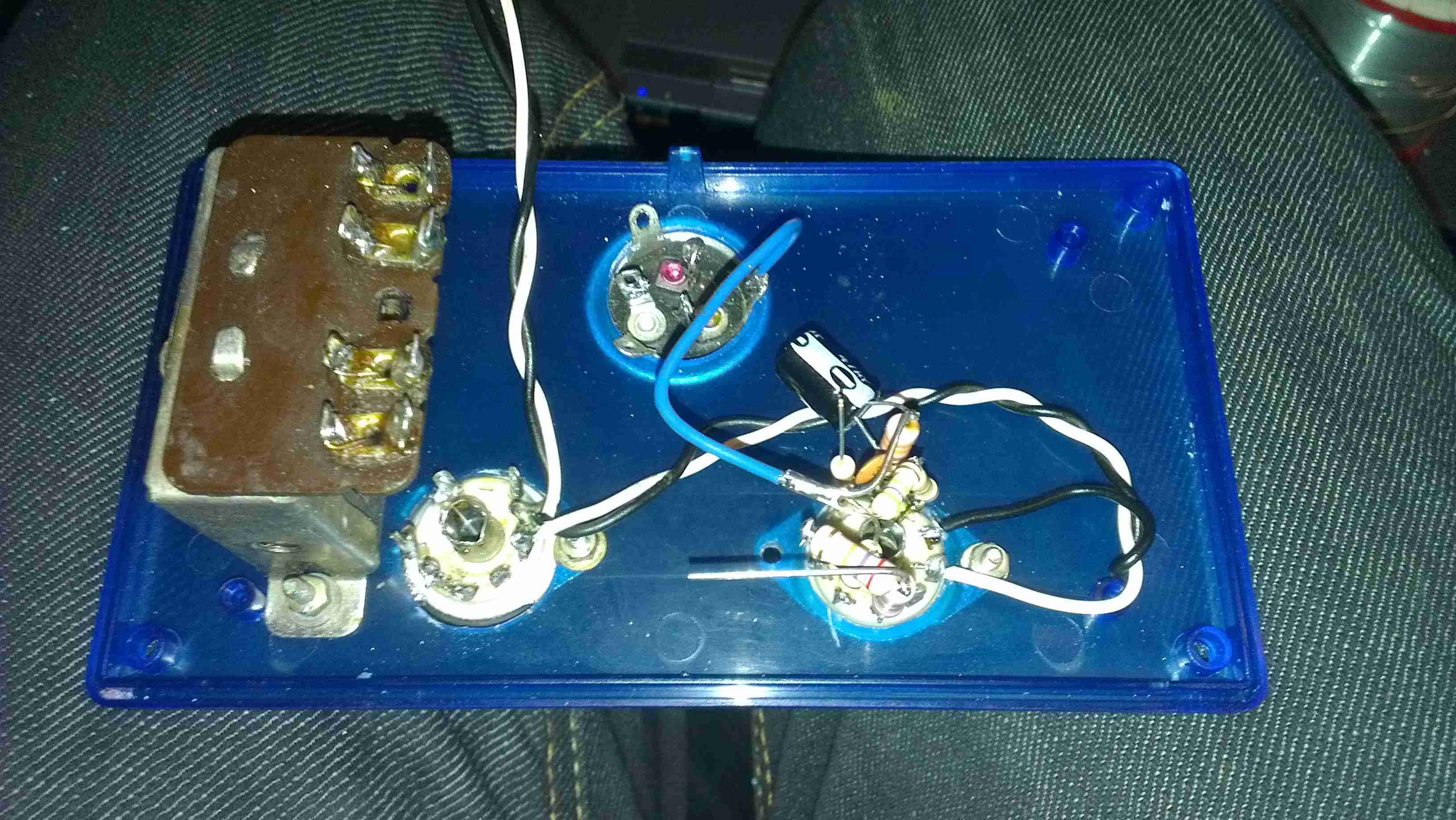
Here the valve holders have been fitted, along with the output transformer, DC smoothing capacitor & the filament wiring, into the top of the plastic housing. At this point all the components that complete the amplifier section are soldered to the bottom of the right hand valve holder.

Wiring
Wiring

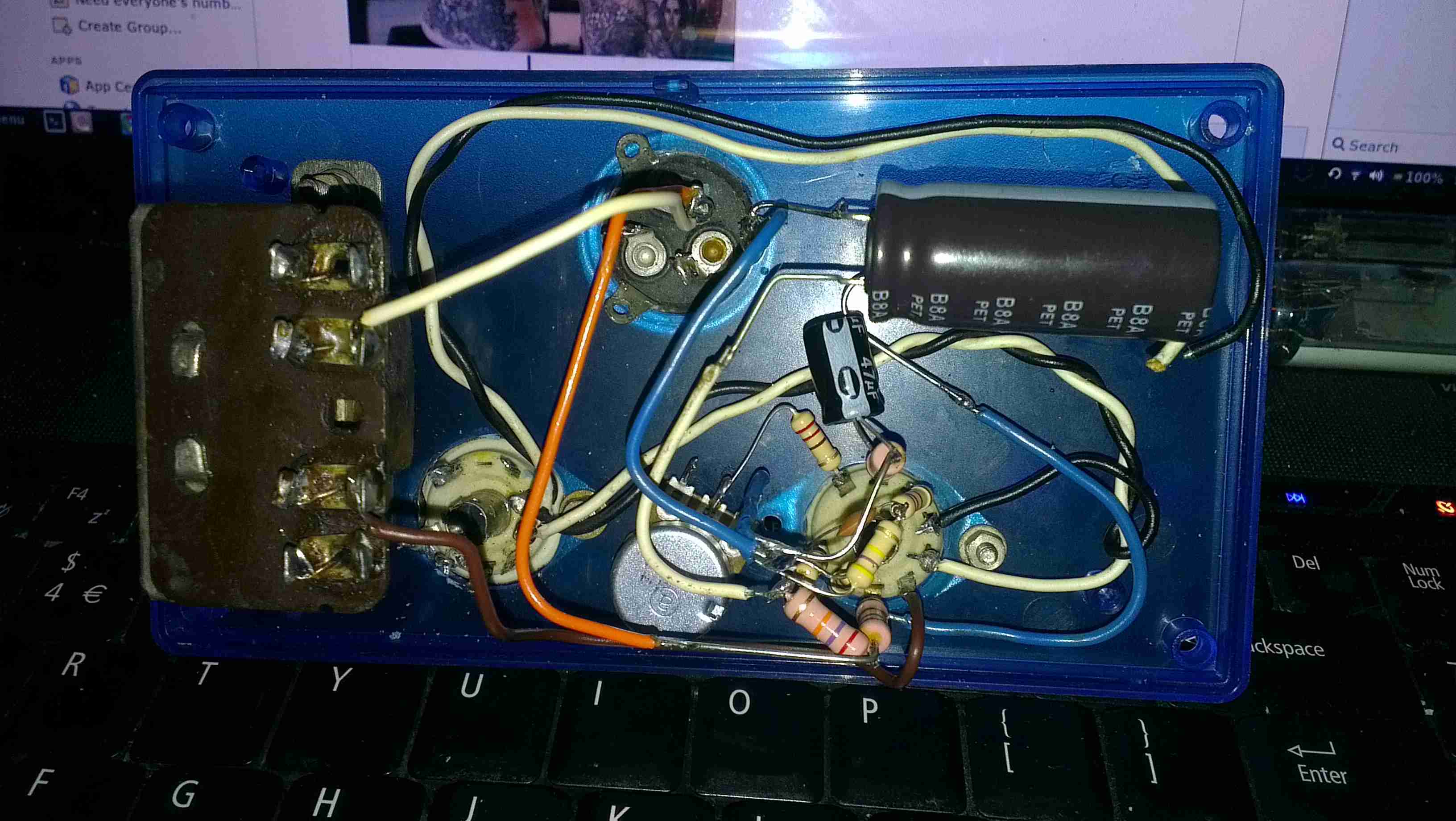
Starting the wiring between the valves & the power supply components. The volume control pot is fitted between the valve holders.

Valves Test Fit
Valves Test Fit

The valves here are test fitted into their sockets, the aluminium can at the back is a triple 32uF 250v electrolytic capacitor for smoothing the B+ rail.

Amplifier Section First Test

First test of the amplifier, with the speaker from the 1960’s tape recorder from which the valves came from. the 200v DC B+ supply & the 6.3v AC filament supply is derived from the mains transformer in the background.

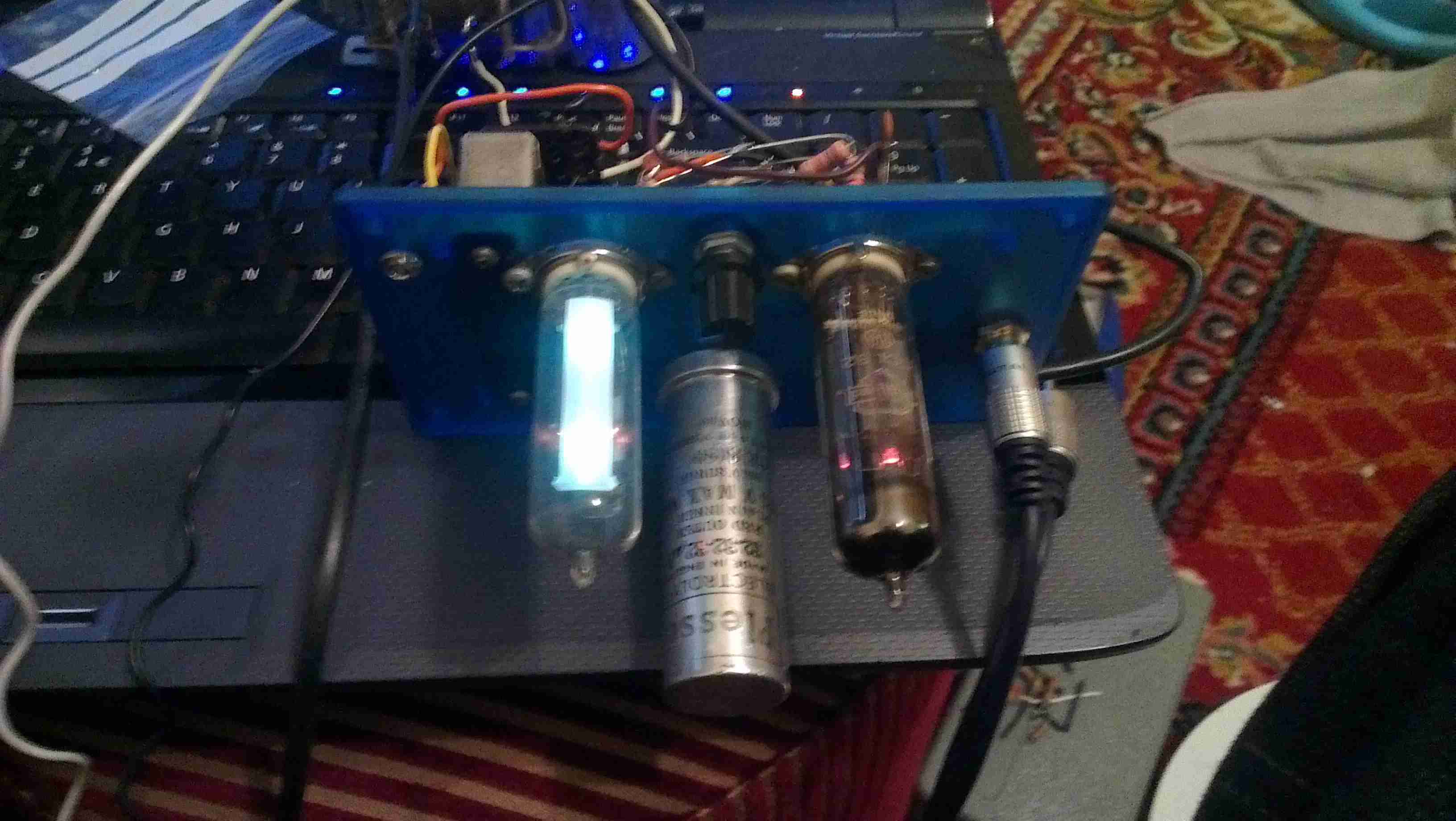
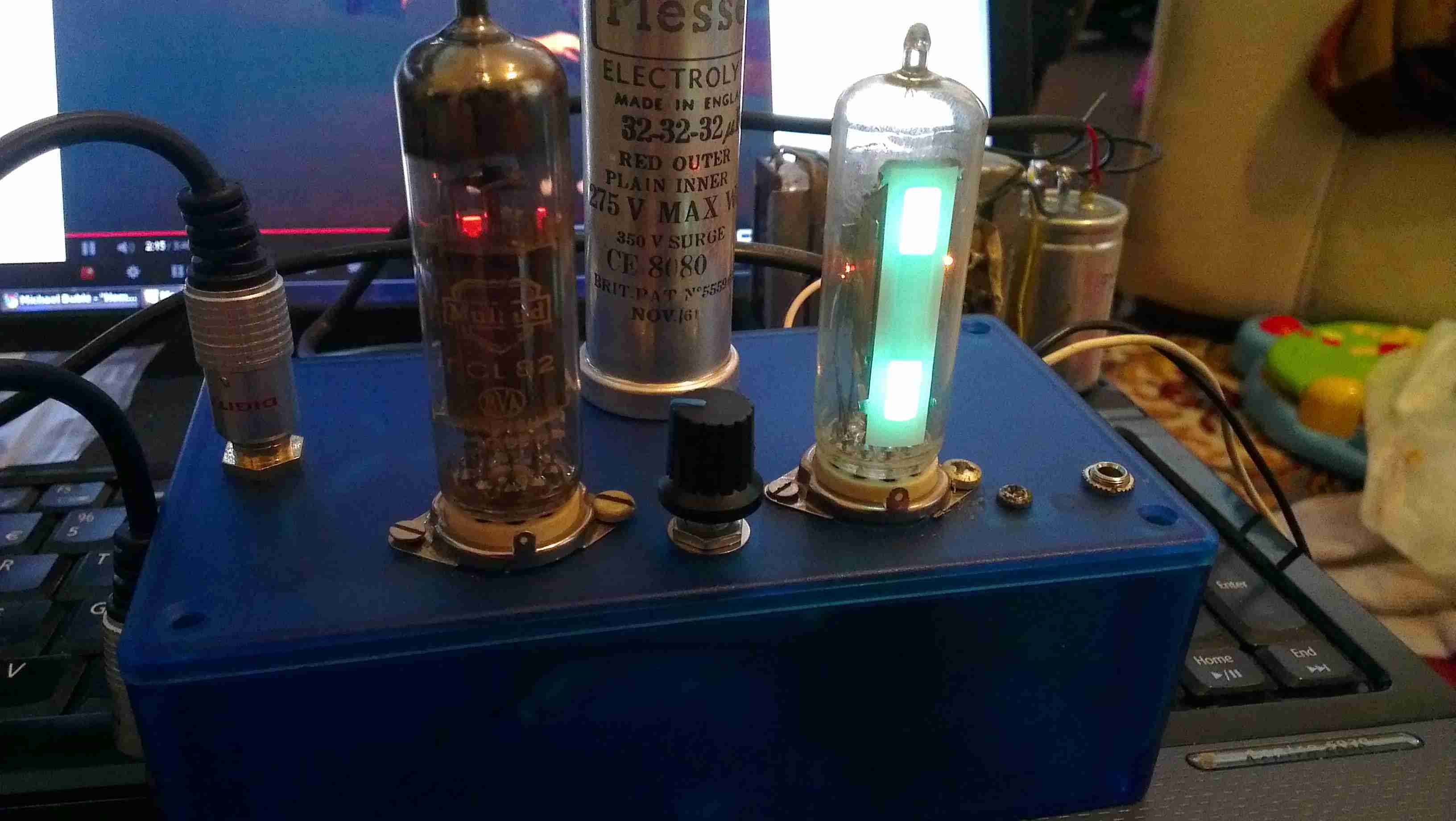
Magic Eye Tube Added

Here the magic eye tube has been fitted & is getting it’s initial tuning to the amplifier section. This requires selecting combinations of anode & grid resistors to set the gap between the bars while at no signal & picking a coupling RC network to give the desired response curve.

Final Test
Final Test

Here both valves are fitted & the unit is sitting on it’s case for final audio testing. the cathodes of the ECL82 can be clearly seen glowing dull red here.


In the final section, I will build a SMPS power supply into the unit to allow it to be powered from a single 12v DC power supply.

Posted on Leave a comment

XM2000 Marine VHF Radio

Radio
Radio

Here is an old XM2000 marine VHF tranciever.

Internal View
Internal View

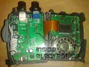
Here is the casing split, with the main CPU board & display on the right, & the RF tranciever board on the left.

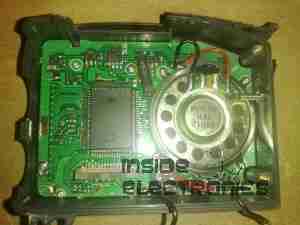
Main CPU
Main CPU

View of the main CPU board, with the mic & loudspeaker on the right hand side.
The channel display is on the reverse side of the PCB.

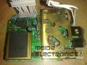
RF Board
RF Board

View of the RF board, with it’s brass shielding attached. This radio will transmit at 5W max.

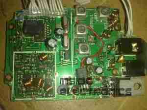
RF Shields Removed
RF Shields Removed

Shielding removed, power regulation bottom right corner of the board, tranciever on the left.

PCB Front
PCB Front

CPU board removed from the casing, showing the LCD & the user buttons to the left.

Posted on Leave a comment

Sanyo Talkbook VAS

Front
Front

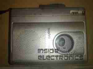
Here is a Sanyo tape recorder, with built in voice activation. Takes standard audio cassettes.
Here visible is the speaker on the left, microphone is on the right of the tape window. The tape counter is at the top.

Back Removed
Back Removed

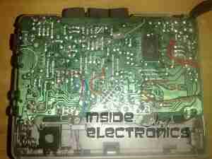
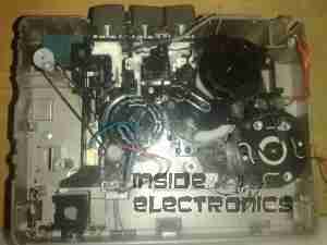
Back cover removed from the unit, showing the PCB & the connections. The IC is the controller/amplifier.

PCB
PCB

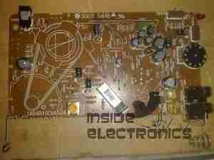
Top of the PCB, control switches, volume potentiometer & microphone/headphone sockets on the right. DC power jack top left. Switch bottom centre senses what mode the tape drive is in.

Tape Deck
Tape Deck

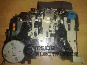
Rear of the tape deck, main drive motor is bottom right, driving the capstan through a drive belt. This drives the tape spools through a series of gears & clutches. Belt going to top left drives the tape counter.

Drive
Drive

Front of the tape drive. Read/write head is top centre. Blue head is bulk erase head used during recording.

Speaker
Speaker

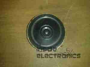
Main speaker. 8Ω 0.25W.

Counter
Counter

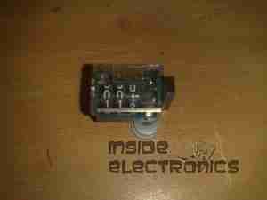
Simple mechanical tape counter.

Posted on Leave a comment

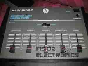
Bandridge VA-315

Front Panel
Front Panel

This is a small audio mixer, marketed for camcorder audio dubbing.

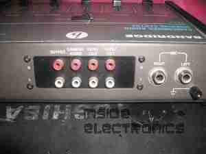
Rear Panel
Rear Panel

I/O Panel on the rear of the unit. Contains a small preamp, but will not drive speakers directly. Power is a 9v battery or plugpack.

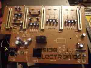
PCB Front
PCB Front

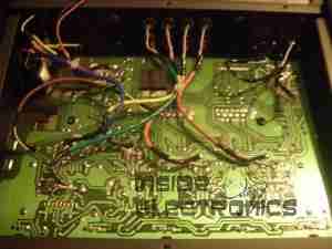
Front of the PCB removed from the case. Mic preamp bottom right corner. Each channel has it’s own Preamp IC between the faders.

PCB Rear
PCB Rear

Rear of the PCB.