Posted on 10 Comments

Camcorder CRT Viewfinder

CRT Assembly
CRT Assembly

Here are the viewfinder electronics from a 1984 Hitachi VHS Movie VM-1200E Camcorder. These small CRT based displays accept composite video as input, plus 5-12v DC for power.

Screen
Screen

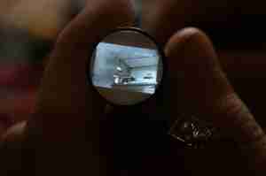
Here is the front face of the CRT, diameter is 0.5″.
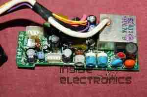
Power Board
Power Board

Closeup view of the PCB, there are several adjustments & a pair of connectors. Socket in the upper left corner is the power/video input. Pinout is as follows:

  1. Brown – GND
  2. Red – Video Input
  3. Orange – +12v DC
  4. Yellow – Record LED
The potentiometers on the PCB from left:
  1. H. ADJ
  2. V. ADJ
  3. BRIGHT
  4. FOCUS
PCB Part Number reads: EM6-PCB
This unit utilises the BA7125L deflection IC.
Solderside
Solderside
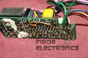
Reverse side of the PCB, very few SMT components on this board.
Tube Assembly
Tube Assembly
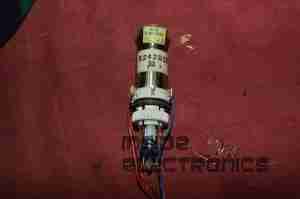
Here is an overall view of the CRT assembly with scan coils. Tube model is NEC C1M52P45.
Electron Gun
Electron Gun

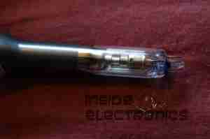
Closeup view of the CRT neck, showing the electron gun assembly.
 

CCTV Camera
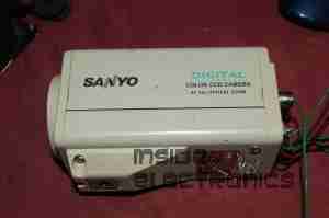
CCTV Camera

The old CCTV camera used to feed a composite signal to the CRT board. Sanyo VCC-ZM300P.
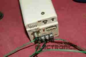
CCTV Camera Connections

Connections at the back of the camera. Red & Black pair of wires lead to 12v power supply, Green & Black pair lead to the CRT board’s power pins. Seperate green wire is pushed into the BNC video connector for the video feed. video ground is provided by the PSU’s ground connection.
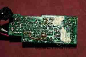
Connections
Connections

Finally the connections at the CRT drive board, left to right, +12v, Video, GND.
Screen Operation
Screen Operation

Display taking video signal from the CCTV camera.

Posted on Leave a comment

Bandridge VA-315

Front Panel
Front Panel

This is a small audio mixer, marketed for camcorder audio dubbing.

Rear Panel
Rear Panel

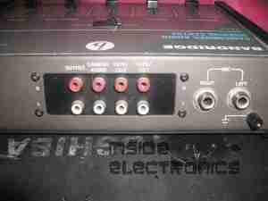
I/O Panel on the rear of the unit. Contains a small preamp, but will not drive speakers directly. Power is a 9v battery or plugpack.

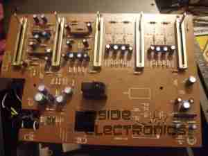
PCB Front
PCB Front

Front of the PCB removed from the case. Mic preamp bottom right corner. Each channel has it’s own Preamp IC between the faders.

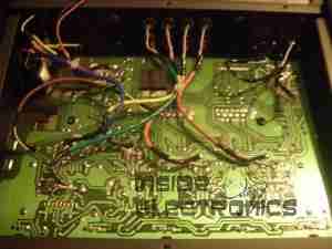
PCB Rear
PCB Rear

Rear of the PCB.