Posted on 10 Comments

Sony HVC-3000P Trinicon Camera Teardown

Camera Left
Camera Left

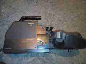
Following on from the viewfinder teardown, here’s the rest of the camera. This unit dates back to 1980, and is made almost exclusively of cast aluminium. Very little plastic has been used here & only for the bits that the user comes into contact with. This camera is based around the Sony Trinicon camera tube system, technology dating back before CCDs. There aren’t many controls on this side of the camera, only the record button, which is hidden behind the camera handgrip.
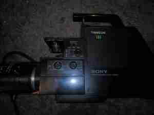
Camera Right
Camera Right

The other side of the camera has most of the controls for the picture.
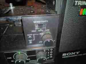
Image Controls
Image Controls

The image controls inclue auto / manual iris, white balance & colour balance.
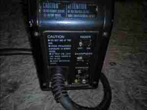
Rear Panel
Rear Panel

Sharpness & fader controls are on the back of the camera, along with the umbilical cable which would have connected to a Betamax recorder.
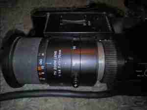
Main Lens
Main Lens

The lens on this camera is massive, at least a kilo of optical glass. Focus control is manual, with both auto & manual zoom control.
Lens Zoom Control
Lens Zoom Control

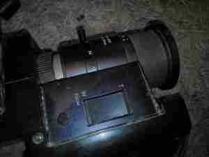
The Zoom controls are on top of the grip, with a button to the rear of the control which I have no idea about. The internal belts are a bit rotted with age so the zoom function doesn’t work great.
Trinicon Control Board

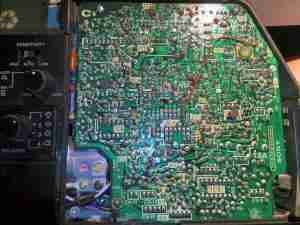
After removing the side covers, the two large PCBs become visible. These units are absolutely packed with electronics. On this side is the Trinicon tube control board, generating all the high voltages for electron beam acceleration, focus & electrostatic deflection of the beam. There’s around 500 volts knocking around on this board, with some rather specialised hybrid modules doing all the high voltage magic.
Video Process Board
Video Process Board

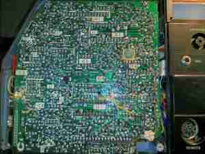
The other side of the camera has the video process board, which performs all the colour separation of the video signal from the tube, processes the resulting signals into a composite video signal, and finally sends it down the umbilical.
Bare Controls
Bare Controls

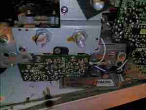
Removing some of the remaining covers exposes the bare video controls, and a small PCB just underneath covered in trimpots to set factory levels.
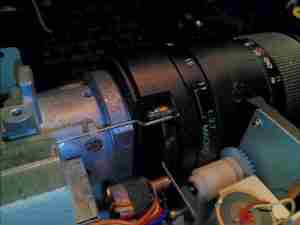
White Balance Filter Arm

The white balance is partially electronic & partially mechanical. This lever actuates a filter inside the lens assrembly.
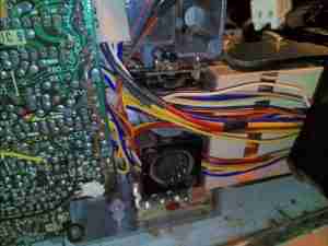
Remote Connector
Remote Connector

A DIN connector offers remote control ability. The large loom of wires disappearing off to the right is dealing with the zoom mechanism & the onboard microphone amplifier. Just under the DIN connector hides the system power supply, inside a soldered can. The can under the white tape is the head end amplifier for the Trinicon video tube.
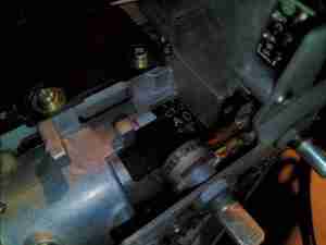
Trinicon Mount
Trinicon Mount

Hiding in the centre of the camera inside the casting is the Trinicon tube assembly itself. The label can just be seen here.
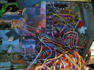
Camera Internals 1
Camera Internals 1

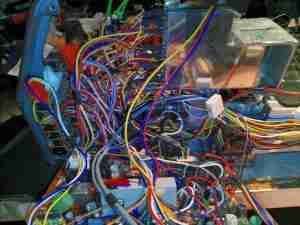
As is typical of 1980’s electronic design, the main boards swing down & are designed to slot into the base casting folded out for repairs. Internally the unit is a rat’s nest of wiring loom. There’s also another shielding can in here nestled between the boards – this is the video sync generator circuit.
Camera Internals 2
Camera Internals 2

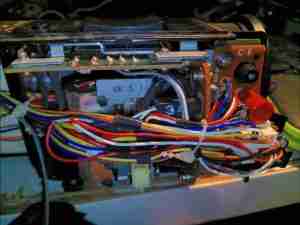
The other side gives a better view of the video sync generator can. I’ll dive into the individual modules later on.
Lens Zoom Assembly
Lens Zoom Assembly

Under the remaining side cover is the zoom assembly & microphone amplifier board. More massive wiring loom hides within.
Video Sync Generator

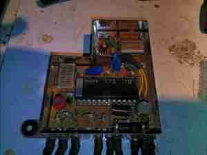
The video sync generator is pretty sparse inside, just a large Sony CX773 Sync Generator IC, with a pair of crystals. There are a couple of adjustments in here for video sync frequencies.
Head End Amplifier
Head End Amplifier

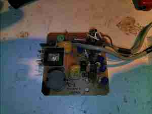
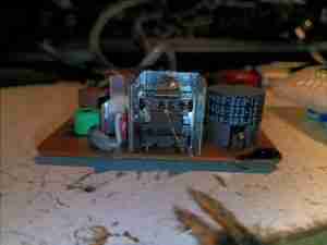
Removed from it’s shielding can, here is the head end amplifier for the Trinicon tube. This very sensitive JFET input amplifier feeds into the main video process board.
Input Transformer
Input Transformer

The Trinicon tube target connects to this input transformer on the front of the amplifier board.
Internal Video Adjustments

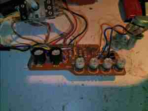
The internal white balance controls are on this small PCB, mounted under the user-accessible controls.
Vidicon Control Board

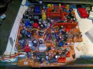
Here’s the main control board responsible for the Trinicon tube & exposure control. Down near the front is the auto-iris circuit, nearer the centre is timing control & at the top is the high voltage power supply & deflection generator ICs.
High Voltage Section

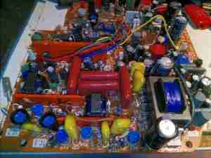
Here’s the high voltage section, the main transformer at right generating the voltages required to drive the video tube. The large orange hybrids here are a pair of BX369 high-voltage sawtooth generators that create the deflection waveforms for the tube. The other large hybrid is a BX382 Fader Control.
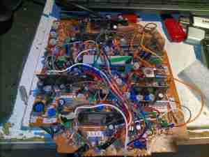
Video Process Board
Video Process Board

The other large board contains all the video process circuitry, all analogue of course. There are a lot of manual adjustment pots on this board.
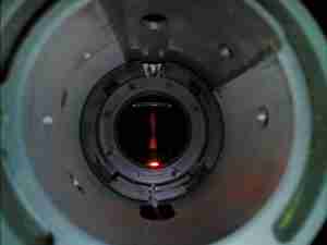
Lens Barrel
Lens Barrel

After removing the lens assembly, the tube assembly is visible inside the barrel casting. Not much to see yet, just the IR filter assembly.
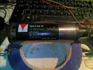
Trinicon Tube Assembly

Here’s the unit removed from the camera. Unfortunately this tube is dead – it shows a lot of target burn on the resulting image, and very bad ghosting on what poor image there is. The Trinicon tube itself is encased in the focus coil assembly, the windings of which are hidden under the shielding.
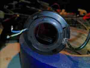
IR Filter
IR Filter

The IR filter is locked into the front of the tube, on a bayonet fitting. The twin target wires are running off to the left, where they would connect to the head end amplifier.
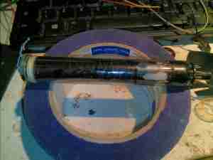
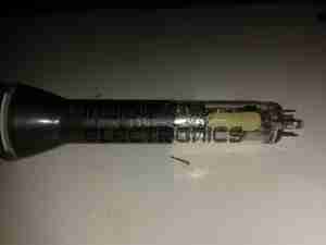
Bare Tube
Bare Tube

After removing the IR filter glass, the Trinicon tube itself is removed from the focus coil assembly. There’s an electron gun at the rear of the tube, like all CRTs, although this one works in reverse – sensing an image projected on the front instead of generating one.
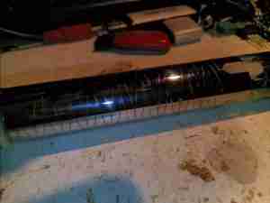
Deflection Plates
Deflection Plates

It’s a little difficult to see, but the electrostatic deflection electrodes in this tube are created from the aluminium flashing on the inside of the glass, in a zig-zag pattern. The interleaving electrodes are connected to base pins by spring contacts at the electron gun end of the tube.
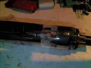
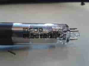
Electron Gun
Electron Gun

The electron gun is mostly hidden by the getter flash & the deflection electrodes, but the cathode can is visible through the glass, along with the spring contacts that make a connection to the deflection electrodes. This is also a very short gun – it doesn’t extend more than about 5mm into the deflection zone. The rest of the tube up to the target is empty space.
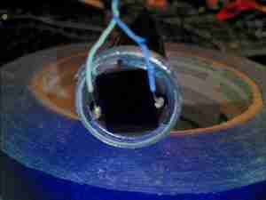
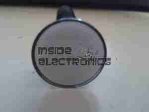
Target
Target

Finally, here’s the target end of the tube. I’m not sure how the wires are attached to the terminals – it certainly isn’t solder, maybe conductive adhesive?
It uses a vertically striped RGB colour filter over the faceplate of an otherwise standard Vidicon imaging tube to segment the scan into corresponding red, green and blue segments. It is used mostly in low-end consumer cameras, though Sony also used it in some moderate cost professional cameras in the 1980s.
Although the idea of using colour stripe filters over the target was not new, the Trinicon was the only tube to use the primary RGB colours. This necessitated an additional electrode buried in the target to detect where the scanning electron beam was relative to the stripe filter. Previous colour stripe systems had used colours where the colour circuitry was able to separate the colours purely from the relative amplitudes of the signals. As a result, the Trinicon featured a larger dynamic range of operation.

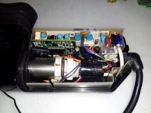
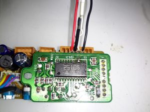
I have the service manuals below for the HVP-2000P & the HVP-4000P, which are very similar cameras, so these may be useful to anyone who has one of these!

Posted on 1 Comment

Panasonic NV-M5 CRT Viewfinder Hack

Viewfinder Circuits
Viewfinder Circuits


The old Panasonic NV-M5 has the standard for the time CRT based viewfinder assembly, which will happily take a composite video signal from an external source.

This viewfinder has many more connections than I would have expected, as it has an input for the iris signal, which places a movable marker on the edge of the display. This unit also has a pair of outputs for the vertical & horizontal deflection signals, I imagine for sync, but I’ve never seen these signals as an output on a viewfinder before.

EVF Schematic
EVF Schematic

Luckily I managed to get a service manual for the camera with a full schematic.
This unit takes a 5v input, as opposed to the 8-12v inputs on previous cameras, so watch out for this! There’s also no reverse polarity protection either.

Pins
Pins

Making the iris marker vanish from the screen is easy, just put a solder bridge between pins 15 & 16 of the drive IC. The important pins on the interface connector are as follows:

Pin 3: GND
Pin 4: Video Input
Pin 5: Video GND
Pins 6: +5v Supply

Posted on Leave a comment

Towpath Motorbike Idiots

This is something I’ve never seen before. Yesterday, on the Lower Peak Forest Canal, a bunch of kids on off-road bikes came thundering down the towpath – one even pulled a wheelie.

There’s considerable motion blur in the photos, as they were doing some speed, at least 30MPH at that stage.

I did get significant verbal abuse of them for having a camera on them, but thee didn’t bother stopping. This happened at the Romiley side of Woodley Tunnel, just past the portal.

Posted on Leave a comment

300th Post! Site Updates, News, Etc

Since this is the 300th post on my blog in the 6 years I’ve been at this, I figured I’d do a post with recent site updates & some news.

Site Look

There haven’t been many updates to the general look of the site for quite a while, with some help of a friend I managed to get a new ticker added to the header, which saves on post count for upcoming projects & posts.
The header image is also dynamic, picking randomly from a collection of images, mostly from previous posts, and a few that started as messing about with a camera & turned out looking quite good.

Site Support

Also added to the site’s look is a Tip Jar on the right hand side, so thankful readers can donate something if I’ve managed to post something remotely helpful ;).
People that know me personally know I hate ads with a passion, and as such ads will have no place on my blog for as long as it’s visible on the intertubes. The site does cost quite a significant (to me anyway) amount of cash to keep going, not to mention time, so any donations would be more than welcome!
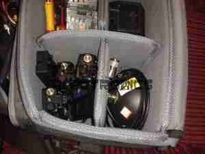
Radio-Based Posts

I haven’t done any proper Ham Radio based posts in quite a while, mainly due to me not having anything to share on the subject, unfortunately it can be a damn expensive hobby & there are other things taking priority at the moment. (Apparently eating & warmth are essentials, according to the missus at least ;)).
There is going to be a round-about radio based post shortly though, so my Ham readers stay tuned!

Boating Posts

Now that we’re in the new year, when the weather returns to something remotely tolerable to be outdoors in, there’ll be much more boating related stuff on the cards, not only trips but engineering jobs onboard.


Posted on Leave a comment

IC Decapping: The Process

As I’ve been posting some photos of decapped ICs lately, I thought I’d share the process I use personally for those that might want to give it a go 😉

The usual method for removing the epoxy package from the silicon is to use hot, concentrated Nitric Acid. Besides the obvious risks of having hot acids around, the decomposition products of the acid, namely NO² (Nitrogen Dioxide) & NO (Nitrogen Oxide), are toxic and corrosive. So until I can get the required fume hood together to make sure I’m not going to corrode the place away, I’ll leave this process to proper labs ;).

The method I use is heat based, using a Propane torch to destroy the epoxy package, without damaging the Silicon die too much.

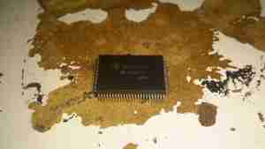
TMS57002 Audio DSP
TMS57002 Audio DSP

I start off, obviously, with a desoldered IC, the one above an old audio DSP from TI. I usually desolder en-masse for this with a heat gun, stripping the entire board in one go.

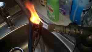
FLAMES!
FLAMES!

Next is to apply the torch to the IC. A bit of practice is required here to get the heat level & time exactly right, overheating will cause the die to oxidize & blacken or residual epoxy to stick to the surface.
I usually apply the torch until the package just about stops emitting it’s own yellow flames, meaning the epoxy is almost completely burned away. I also keep the torch flame away from the centre of the IC, where the die is located.
Breathing the fumes from this process isn’t recommended, no doubt besides the obvious soot, the burning plastic will be emitting many compounds not brilliant for Human health!
Once the IC is roasted to taste, it’s quenched in cold water for a few seconds. Sometimes this causes such a high thermal shock that the leadframe cracks off the epoxy around the die perfectly.

All Your Die Belong To Us

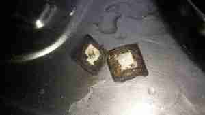
Now that the epoxy has been destroyed, it breaks apart easily, and is picked away until I uncover the die itself. (It’s the silver bit in the middle of the left half). The heat from the torch usually destroys the Silver epoxy holding the die to the leadframe, and can be removed easily from the remaining package.

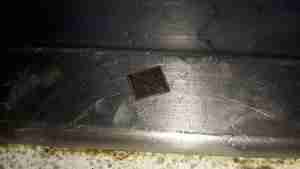
Decapped
Decapped

BGA packages are usually the easiest to decap, flip-chip packages are a total pain due to the solder balls being on the front side of the die, I haven’t managed to get a good result here yet, I’ll probably need to chemically remove the first layer of the die to get at the interesting bits 😉

Slide
Slide

Once the die has been rinsed in clean water & inspected, it’s mounted on a glass microscope slide with a small spot of Cyanoacrylate glue to make handling easier.

Some dies require some cleaning after decapping, for this I use 99% Isopropanol & 99% Acetone, on the end of a cotton bud. Any residual epoxy flakes or oxide stuck to the die can be relatively easily removed with a fingernail – turns out fingernails are hard enough to remove the contamination, but not hard enough to damage the die features.

Once cleaning is complete, the slide is marked with the die identification, and the photographing can begin.

Microscope Mods

I had bought a cheap eBay USB microscope to get started, as I can’t currently afford a proper metallurgical microscope, but I found the resolution of 640×480 very poor. Some modification was required!

Modified Microscope
Modified Microscope

I’ve removed the original sensor board from the back of the optics assembly & attached a Raspberry Pi camera board. The ring that held the original sensor board has been cut down to a minimum, as the Pi camera PCB is slightly too big to fit inside.
The stock ring of LEDs is run direct from the 3.3v power rail on the camera, through a 4.7Ω resistor, for ~80mA. I also added a 1000µF capacitor across the 3.3v supply to compensate a bit for the long cable – when a frame is captured the power draw of the camera increases & causes a bit of voltage drop.

The stock lens was removed from the Pi camera module by careful use of a razor blade – being too rough here *WILL* damage the sensor die or the gold bond wires, which are very close to the edge of the lens housing, so be gentle!

Mounting Base
Mounting Base

The existing mount for the microscope is pretty poor, so I’ve used a couple of surplus ceramic ring magnets as a better base, this also gives me the option of raising or lowering the base by adding or removing magnets.
To get more length between the Pi & the camera, I bought a 1-meter cable extension kit from Pi-Cables over at eBay, cables this long *definitely* require shielding in my space, which is a pretty aggressive RF environment, or interference appears on the display. Not surprising considering the high data rates the cable carries.
The FFC interface is hot-glued to the back of the microscope mount for stability, for handheld use the FFC is pretty flexible & doesn’t apply any force to the scope.

Die Photography

Since I modified the scope with a Raspberry Pi camera module, everything is done through the Pi itself, and the raspistill command.

Pi LCD
Pi LCD

The command I’m currently using to capture the images is:
raspistill -ex auto -awb auto -mm matrix -br 62 -q 100 -vf -hf -f -t 0 -k -v -o CHIPNAME_%03d.jpg

This command waits between each frame for the ENTER key to be pressed, allowing me to position the scope between shots. Pi control & file transfer is done via SSH, while I use the 7″ touch LCD as a viewfinder.

The direct overhead illumination provided by the stock ring of LEDs isn’t ideal for some die shots, so I’m planning on fitting some off-centre LEDs to improve the resulting images.

Image Processing

Obviously I can’t get an ultra-high resolution image with a single shot, due to the focal length, so I have to take many shots (30-180 per die), and stitch them together into a single image.
For this I use Hugin, an open-source panorama photo stitching package.

Hugin
Hugin

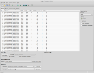
Here’s Hugin with the photos loaded in from the Raspberry Pi. To start with I use Hugin’s built in CPFind to process the images for control points. The trick with getting good control points is making sure the images have a high level of overlap, between 50-80%, this way the software doesn’t get confused & stick the images together incorrectly.

Optimiser
Optimiser

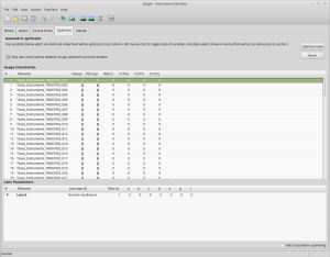
After the control points are generated, which for a large number of high resolution images can take some time, I run the optimiser with only Yaw & Pitch selected for all images.

Optimising
Optimising

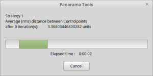
If all goes well, the resulting optimisation will get the distance between control points to less than 0.3 pixels.

Panorama Preview
Panorama Preview

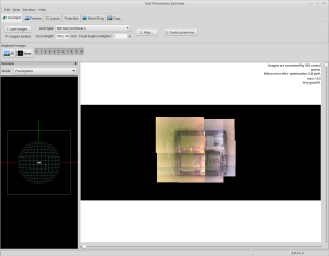
After the control points & optimisation is done, the resulting image can be previewed before generation.

Texas Instruments TMS67002

After all the image processing, the resulting die image should look something like the above, with no noticeable gaps.

Posted on Leave a comment

Mobile Radio Shack Bag

There are times when I am frequently away from home base, usually either on the canal system or at a festival. During these times it’s very handy to be able to just grab a bag, without having to be concerned about sorting everything out.

This post will only detail the portable shack bag. The power supply kit that goes along with it with be detailed in another post.

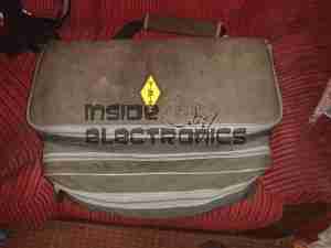
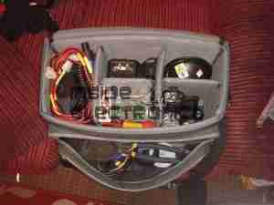
The bag I use is an VHS Camcorder bag from the early 80’s. It’s very well built, & copes easily with the weight of all the radio gear.

Total weight for this system is 13.4lbs (6kg).

Mobile Radio Bag
Mobile Radio Bag

Above is the bag packed. Obligatory International Ameteur Radio Symbol patch front & centre. Being an old camera bag, this easily slings over the shoulder, with it’s padded strap.

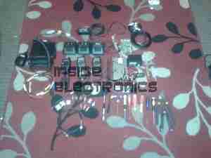
Current Equipment
Current Equipment

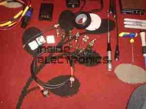
Here is all the current equipment laid out. All the equipment to enable me to set up a station anywhere.
In the following photos I will go into the details.

Main Radio
Main Radio

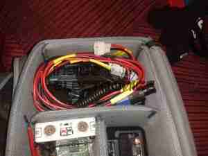
First off, my main radio. This is the same Wouxun KG-UV950P mobile rig I have posted about previously. I have heatshrunk the power cable to keep it together & attached my standard power connector to the end. More on these later on.

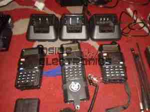
HTs
HTs

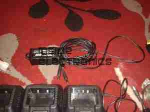
In the bag I also carry three Baofeng UV-5R handhelds. Extremely useful for short range site communications, along with their charger bases. The charging base on the right has been slightly modified to support charging of my main LED torch as well, which uses similar Li-Ion based packs as the Baofengs.

Baofeng 12v Charger
Baofeng 12v Charger

As the charger bases for the Baofeng HTs take a supply of 10v DC, I have constructed a 12v adaptor system for them. (Which utter prat of an engineer at Baofeng picked 10v?)

Linear Amplifier & SWR Meter

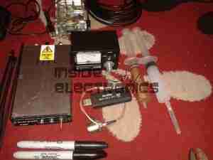
Also included is a small Alinco ELH-2320 35W 2m linear amplifier. This was given to me from the local HackSpace in Manchester. (They don’t have any ham members, besides myself). Also here is my small SWR & Power meter, SDR kit & a pair of syringes. These are filled respectively with Copaslip copper loaded grease, (very good for stopping fasteners exposed to the weather from seizing up), and dielectric silicone grease. (I use this stuff for filling connectors that are exposed to the weather – keeps the water out).

Tools
Tools

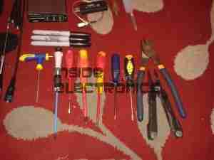
I always keep essential tools in the bag, here is the small selection of screwdrivers which fit pretty much any screw fastener around, my heavy-duty cable shears (these buggers can cut through starter cable in one go!) and my trusty Gerber Diesel multitool.

Magmount & Pi
Magmount & Pi

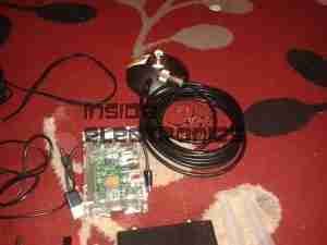
Main antenna magmount & a spare Raspberry Pi.

Antenna, Patch Leads, Etc.

Finally, the antennas for the HTs, main dual-band antenna (Nagoya SP-45) for the magmount, a small selection of spare plugs, sockets & adaptors. Also here is a roll of self-amalgamating tape, very handy for waterproofing wiring connections (especially when used in conjunction with the silicone grease), & a roll of solder wick.

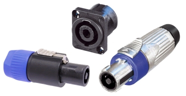
Now, the main power connectors of choice for my equipment are Neutrik SpeakOn type connectors:

Neutrik SpeakOn
Neutrik SpeakOn

These connectors have many advantages:

  • They are positive locking connectors. No more loose connections.
  • They have a high continuous current rating of 30A RMS.
  • Relatively weather resistant.

Also, they have two pairs of pins – and as some of my bigger non-radio related equipment is 24v, this allows me to use a single set of plugs for everything. Without having to worry about plugging a 12v device into a 24v socket, and letting out the magic blue genie.

Once everything is packed up, here’s the bag:

Packed
Packed

Everything has a neat little pocket for easy access. Some closeups below.

HTs, Magmount
HTs, Magmount
Chargers, Amplifier
Chargers, Amplifier
Main Radio
Main Radio
Small Stuff
Small Stuff

I will post more about my portable power system later on, as this bit of my kit is being revamped at the moment.

Stay tuned!

Posted on Leave a comment

Another Viewfinder CRT

Here’s another viewfinder CRT, removed from a 1980’s vintage VHS camera I managed to get cheap from eBay.

This unit is very similar to the last one I posted about, although there are a few small differences in the control circuitry.

Viewfinder Schematic
Viewfinder Schematic – Click to Embiggen

Here’s the schematic, showing all the functional blocks of the viewfinder circuitry. An integrated viewfinder IC is used, which generates all the required scan waveforms for the CRT.
On the left is the input connector, with the power & video signals. Only pins 2 (GND), 3 (Composite video), & 4 (+8v) are needed here. Pin 1 outputs a horizontal sync signal for use elsewhere in the camera, while pin 5 fed the recording indicator LED.

To make connection easier,  I have rearranged the wires in the input connector to a more understandable colour scheme:

Input Connector
Input Connector

Red & Blue for power input, & a coax for the video. For the video GND connection, I have repurposed the Rec. LED input pin, putting a shorting link across where the LED would go to create a link to signal ground. Keeping this separate from the power GND connection reduces noise on the CRT.

Viewfinder CRT Assembly

Here’s the complete assembly liberated from it’s plastic enclosure.

PCB Closeup
PCB Closeup

Closeup of the control PCB. The 3 potentiometers control the CRT brightness, focus & vertical size.

M01KGG007WB CRT
M01KGG007WB CRT

The tiny CRT. Only ~60mm in length, with an 18mm screen size. This tube runs on +2294v final anode voltage. Much higher than I expected.

Electron Gun Closeup

The electron gun assembly, with the cathode, focus & final anode cups.

Phosphor Screen
Phosphor Screen

This screen is just a little bigger than a UK 5p piece! A marvel of precision engineering.


Posted on Leave a comment

455nm Laser Head

Aixiz Module
Aixiz Module

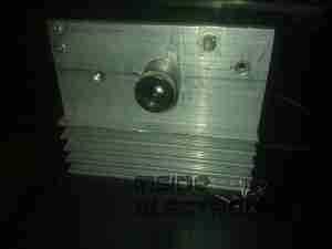
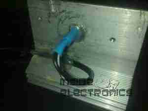
Here’s my prototype 455nm laser head, constructed from the front section of an Aixiz module threaded into a heatsink from an old ATX power supply. This sink has enough thermal mass for short 1W testing.

Connection
Connection

Connection to the laser diode at the back of the heatsink. Cable is heat shrink covered for strain relief, & hot glued to the sink for extra strain relief.

Beamshot 1
Beamshot 1

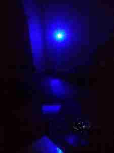
Looking down the beam, laser is under the camera. Operating around 1.2W here

Beamshot 2
Beamshot 2

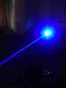
Camera looking towards the laser. Again operating at ~1.2W output power.

Posted on Leave a comment

Motorola V360v

Front
Front

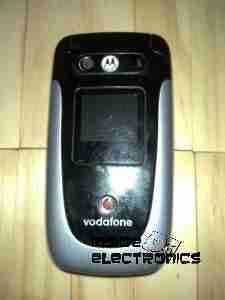
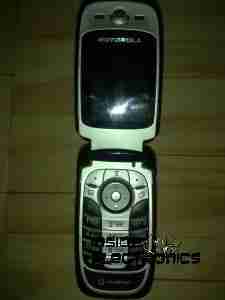
Here is a more modern phone, the Motorola V360v. Features include Dual screens, 640×480 VGA camera, full col

our TFT Main LCD, SD-Micro slot.
Here on the back the grey scale LCD can be seen, with the camera lens to the right of the Motorola logo

Keypad
Keypad

Here the phone is opened showing the keypad & the full colour TFT LCD display.

Battery Compartment
Battery Compartment

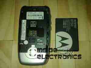
Here the battery is removed from the unit, showing the SIM connector. The antenna cover is still on at the bottom.

Antenna
Antenna

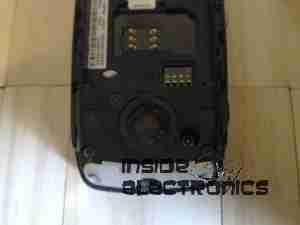
The antenna cover has been removed in this shot, the antenna is the white section at the bottom, With the loudspeaker & the external antenna connector hidden at the right.

PCB
PCB

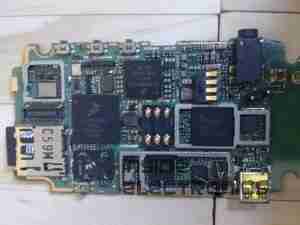
Here is the main PCB. Parts from left are the Bluetooth module at the top, supplied by Broadcom, the SD Card socket at the bottom. Main CPU next to that is the Freescale SC29343VKP. Above right of the CPU is the Freescale SC13890P23A Charger, Power & Audio IC. Below is the SIM card socket. Under the main CPU is the Intel Flash memory IC. ICs inside the shields are the RF sections for transmit & receive.

Cover Removed
Cover Removed

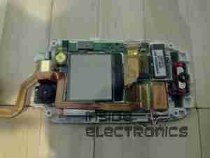
Rear of the display unit showing the monochrome LCD. The camera module on the bottom left. Ear speaker on the far right of the unit.

Main LCD
Main LCD

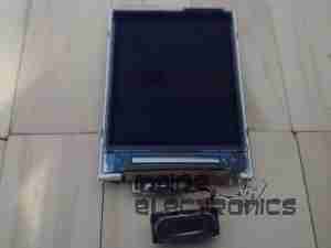
Main colour TFT LCD.

Camera
Camera

Camera module removed from the LCD unit.

Vibra-Motor
Vibra-Motor

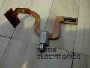
The vibration motor attached to one of the LCD looms.