Posted on Leave a comment

nb Tanya Louise – Oil Cooling Improvements

Temperature Gauges
Temperature Gauges

Since the engine & hydrostatic transmission were installed in the boat a few years back, the hydraulic oil cooler has been in the same fresh water circuit as the engine’s water cooling system, however this has been causing some heat issues with the engine & hydraulic system under a heavy load, such as when I’m using the onboard generator to run the welding gear. The hydraulic oil temp would rise to over 80°C during the course of a long day’s cruising – such temperatures will degrade the oil very quickly, and in turn will cause premature wear of the very expensive hydraulic pumps. (Not to mention increasing the requirement for hydraulic oil changes, which are very expensive). The engine oil has been cooled by a standard automotive oil radiator, with air forced over the matrix by two large fans. This is also pretty inefficient, so another cooler will be added to replace the automotive one.
This cooling requirement is caused by the inefficiency of hydraulic systems – a simple variable displacement piston pump driving a bent-axis piston motor has an overall efficiency of roughly 80%. Given our engine’s max power of 76HP (56.7kW), this gives an energy loss of 15.2HP (11.33kW) at maximum power. This extra heat overloaded the skin tank, resulting in a cooling system that didn’t really work all too well once the engine was hot.

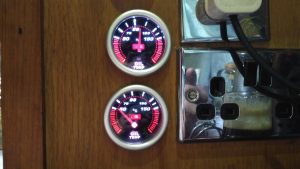
To solve this issue, we’ve decided to run a raw water circuit using the canal to remove the waste heat from the hydraulic system & engine oil, putting less of a heat load on the skin tank to bring the temperatures down to something reasonable. The image above show the system at running temperature after I installed the monitoring instruments. The top gauge is measuring engine oil temperature, at the point where it’s being fed to the bearings. The bottom one is measuring hydraulic oil temperature.

The engine oil temperature does have to be higher than any other cooling circuit on board, to boil off any condensate from the cylinders. Overcooling the oil in the sump will eventually cause sludging as the oil tries to absorb the resulting water. I’m aiming for a system temperature in the engine oil circuit of 95°C-120°C when the engine is under load & at operating temperature.
Raw Water Suction
Raw Water Suction

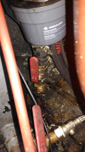
Water from the canal is drawn from a skin fitting installed at the last drydock visit, pulling water through a strainer to remove all the large bits of muck. The large slotted screen on the suction skin fitting keeps larger objects out of the intake.
Raw Water Pump
Raw Water Pump

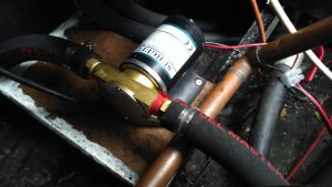
A flexible impeller pump provides the power to move water through the system, in this case about 25L/Min. This pump is a cheap copy of a Jabsco pump from eBay. So far it’s been pretty reliable.
Temperature Senders
Temperature Senders

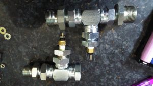
The temperature senders are standard automotive parts, and some adaptors were required to graft them into the oil lines of both systems. The senser’s 1/8″ NPT threads are here fitted into 1/2″ BSP hydraulic fittings.
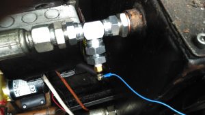
Hydraulic Temperature Sender

Here’s the hydraulic oil sender installed in the drain line from the main propulsion pump, this should give me a pretty good idea of the temperature of the components in the system, the sender is earthed through the steel hydraulic oil tank.
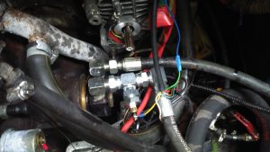
Engine Oil Temperature Sender

The oil temperature sender is installed in the return line to the engine from the heat exchanger. This is measuring the oil temperature the bearings in the engine are being fed with.
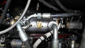
Hydraulic Oil Heat Exchanger

The stack of heat exchangers is located on the starboard side of the engine bay, the large one here is cooling the hydraulic oil, the auxiliary pump is continually circulating the oil from the tank through this, then into the return filter on the top of the tank.
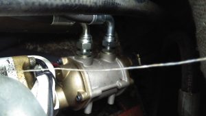
Engine Oil Heat Exchanger

The engine oil is fed through this much smaller heat exchanger mounted on the back of the large hydraulic cooler, the last in the circuit before the water is discharged back overboard through a skin fitting.
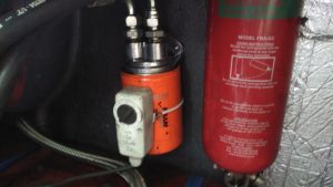
Remote Oil Filter
Remote Oil Filter

As we’ve got the diverter block on the side of the engine where the oil filter should be, a remote oil filter is fitted above the fuel tank. The thermostat strapped on operates the main engine bay ventilation fans, switching them on once the engine oil reaches 60°C.
Posted on Leave a comment

Boating: Drydock Time – New Running Gear & Rudder Modifications

New Shaft & Prop
New Shaft & Prop

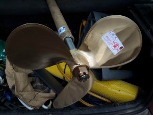
We’re now on the final leg of the jobs to be done on the boat! Above is the new prop & shaft, supplied to us by Crowther Marine over in Royton. To fit our current stern tube & gland, the shaft is the same diamter at 1-3/8″. Unfortunately no 4-blade props were available, so I had to go for a 17×11 left-hand, but with a much larger blade area than the old one.

Propellers
Propellers

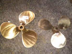
Here’s the old prop on the right, with the new one on the left, amazing how different 1 inch of diameter actually looks. The opposite hand of the new prop makes no difference in our case, as I can simply switch the hoses to the hydraulic motor on the shaft to make everything reverse direction.

Stripper
Stripper

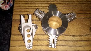
Above is the solution to my problem of no weed hatch – a Stripper Rope Cutter from Ambassador Marine. This device has some seriously viciously sharp cutting teeth to help clear any fouling from the prop in operation. Only time will tell if it’s effective at allowing me to stay out of the canal manually removing the crap!

Cutless Bearing
Cutless Bearing

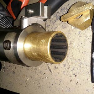
We finally got the bearing mount finished, by S Brown Engineering in Stockport. This is made from Stainless steel to stop the bearing corroding in place & becoming a real arse to replace. Set screws are fitted to make sure the bearing doesn’t move in service.
Attached to the side of the bearing housing is the fixed blade mounting for the Stripper Rope Cutter.

Bearing Test Fit
Bearing Test Fit

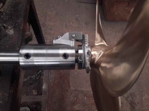
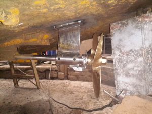
Above is everything fitted to the shaft for a test before the gear went into it’s home in the stern tube. The Stripper mounts behind the prop, clamped to the shaft. The 3 moving blades move against the fixed blade like a mechanised pair of scissors.

Bearing Strut Welding

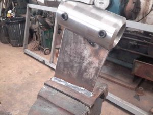
10mm steel plate has been used to make the strut for the bearing tube, welded together. In the case of the joint between the stainless tube & the carbon steel strut, special welding rods were needed, at the price of £2 a rod! Using mild steel rods to weld stainless could result in cracking of the welds. Not a good thing on a prop shaft support bearing.

Sand Blasted Hull
Sand Blasted Hull

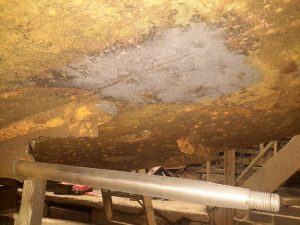
Most of the old tube has been cut away to make room for the new bearings, and the bottom of the hull has been sand-blasted ready for welding.

Running Gear Mounted

The bearing mount is welded to the hull, the Stripper & the prop are fitted to the end of the shaft. There’s 1.5″ of clearance from the blade tips to the hull plating. The rudder has about an inch of clearance to the end of the shaft.

Rudder Fence
Rudder Fence

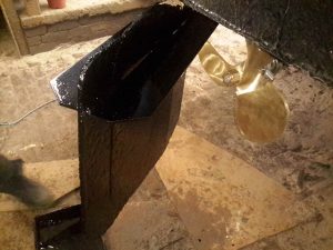
To help keep the prop wash down, directing more of the force into moving the vessel rather than creating a nice rooster tail, a pair of plates has been welded onto the rudder. These also provide a handy step should someone fall in ;).

Posted on Leave a comment

Boat Stuff: Bowman Oil Cooler

Bowman Oil Cooler
Bowman Oil Cooler

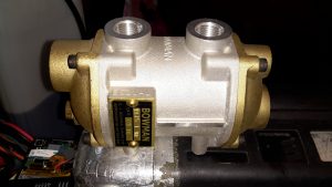
To solve some engine oil overheating problems on board nb Tanya Louise, we decided to replace the air-over-oil cooler, with an water-over-oil cooler, with separate cooling drawn straight from the canal, as the skin tanks are already overloaded with having to cope with not only cooling the engine coolant, but also the hydraulic system oil as well.
These units aren’t cheap in the slightest, but the construction quality & engineering is fantastic.

Tube End Plate
Tube End Plate

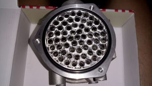
Unbolting the end cover reveals the brass tube end plate, soldered to all the core tubes in the cooler. An O-Ring at each end seals both the end cover & the interface between the tube plate & the outer casing.

End Caps
End Caps

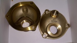
The end caps have baffles cast in to direct the cooling water in a serpentine path, so the oil gets the best chance at dissipating it’s heat to the water.

Tube Stack
Tube Stack

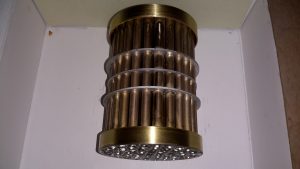
The oil side of the system is on the outside of the tubes, again baffles placed along the stack direct the oil over the highest surface area possible.

Outer Shell
Outer Shell

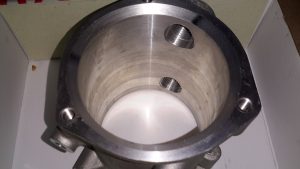
The outer shell is just a machined alloy casting, with no internal features.

Posted on Leave a comment

nb Tanya Louise Radio Install Part 1

I often find myself carrying by go bag up to the boat during trips, so I can do some radio. However at 16lbs it’s a pain on public transport. A fixed radio was required! Another Wouxun GK-UV950P was ordered, and the fact that the head unit is detachable from this radio makes a clean install much easier.

Mounting Bracket
Mounting Bracket

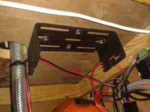
I found a nice spot under a shelf for the main radio unit, above is the mounting bracket installed.
This location is pretty much directly behind where the head unit is placed, but the audio is a bit muffled by the wooden frame of the boat & some external speakers will be required for the future.

Main Radio Unit
Main Radio Unit

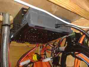
Here’s the main radio unit mounted on it’s bracket, with the speakers facing down to improve the audio slightly. I used the supplied interface cable for the head unit, even though it’s too long. I do have the tools to swage on new RJ-45s, but the stuff is a pain to terminate nicely & I really just couldn’t be bothered. So it’s just coiled up with some ties to keep it tidy. Main power is provided directly from the main DC bus. (880Ah total battery capacity, plus 90A engine alternator, 40A solar capacity).

Rat's Nest
Rat’s Nest

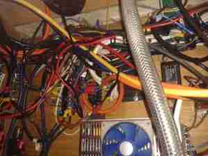
Here’s the main DC bus, with the distribution bars. With the addition of new circuits over the years, this has become a little messy. At some point some labelling would be a good idea!

Radio Face Plate
Radio Face Plate

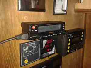
Finally, the head unit is installed in a spot on the main panel. It does stick out a little more than I’d like, but it’s a lot of very dusty work with the router to make a nice hole to sink it further in. All my local repeaters & 2m/70cm simplex are programmed in at the moment.

Antenna Magmount
Antenna Magmount

I’ve got a Nagoya SP-80 antenna on a magmount for the radio, a magmount being used due to the many low bridges & trees on the canal. (It’s on the roof next to the first solar panel above). I prefer it to just fall over instead of having the antenna bend if anything hits it!

Part 2 will be coming soon with details of the permanent antenna feeder.

73s for now!

Posted on Leave a comment

Raspberry Pi Timelapse Video – Canal Cruising

A break from normal programming now to show a weekend canal cruise on the Macclesfield canal. Going from Marple to Poynton & returning later in the afternoon. This video was shot with the Raspberry Pi waterproofed with the PiCE From Elson Designs.

Posted on Leave a comment

Marine Potable Water Management System

LCD Panel
LCD Panel

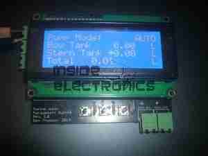
Having two separate water tanks on nb Tanya Louise, with individual pumps, meant that monitoring water levels in tanks & keeping them topped up without emptying & having to reprime pumps every time was a hassle.
To this end I have designed & built this device, to monitor water usage from the individual tanks & automatically switch over when the tank in use nears empty, alerting the user in the process so the empty tanks can be refilled.

Based around an ATMega328, the unit reads a pair of sensors, fitted into the suction line of each pump from the tanks. The calculated flow is displayed on the 20×4 LCD, & logged to EEPROM, in case of power failure.

Water Flow Sensor
Water Flow Sensor

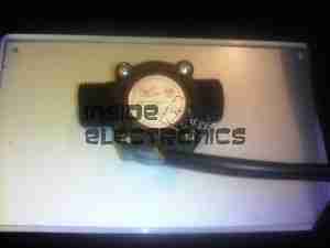
When the tank in use reaches a preset number of litres flowed, (currently hardcoded, but user input will be implemented soon), the pump is disabled & the other tank pump is enabled. This is also indicated on the display by the arrow to the left of the flow register. Tank switching is alerted by the built in beeper.
It is also possible to manually select a tank to use, & disable automatic operation.
Resetting the individual tank registers is done by a pair of pushbuttons, the total flow register is non-resettable, unless a hard reset is performed to clear the onboard EEPROM.

Main PCB
Main PCB

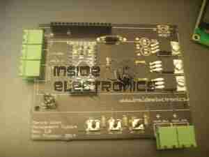
View of the main PCB is above, with the central Arduino Pro Mini module hosting the backend code. 12-24v power input, sensor input & 5v sensor power output is on the connectors on the left, while the pair of pump outputs is on the bottom right, switched by a pair of IRFZ44N logic-level MOSFETS. Onboard 5v power for the logic is provided by the LM7805 top right.

Code & PCB design is still under development, but I will most likely post the design files & Arduino sketch once some more polishing has been done.