Posted on Leave a comment

First Alert CO-FA-9B Carbon Monoxide Alarm Teardown

CO-FA-9B Alarm
CO-FA-9B Alarm

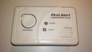
Here’s another domestic CO Alarm, this one a cheaper build than the FireAngel ones usually use, these don’t have a display with the current CO PPM reading, just a couple of LEDs for status & Alarm.

Rear
Rear

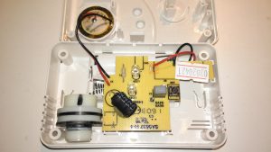
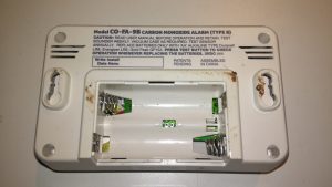
This alarm also doesn’t have the 10-year lithium cell for power, taking AA cells instead. The alarm does have the usual low battery alert bleeps common with smoke alarms though, so you’ll get a fair reminder to replace them.

Internals
Internals

Not much at all on the inside. The CO sensor cell is the same one as used in the FireAngel alarms, I have never managed to find who manufactures these sensors, or a datasheet for them unfortunately.

PCB Top
PCB Top

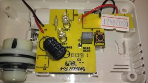
The top of the single sided PCB has the transformer for driving the Piezo sounder, the LEDs & the test button.

PCB Bottom
PCB Bottom

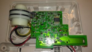
All the magic happens on the bottom of the PCB. The controlling microcontroller is on the top right, with the sensor front end on the top left.

Circuitry Closeup
Circuitry Closeup

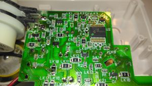
The microcontroller used here is a Microchip PIC16F677. I’ve not managed to find datasheets for the front end components, but these will just be a low-noise op-amp & it’s ancillaries. There will also be a reference voltage regulator. The terminals on these sensors are made of conductive plastic, probably loaded with carbon.

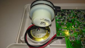
Sensor Cell & Piezo Disc

The expiry date is handily on a label on the back of the sensor, the Piezo sounder is just underneath in it’s sound chamber.

Posted on Leave a comment

Quick Tool Review – Engineer PA-09 Crimping Pliers

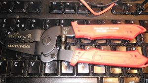
For a while now I’ve been attaching terminals such as Molex KK Dupont, & JST PH to wire ends with a lot of patience & a very fine soldering iron, however this method takes a lot of time, and with terminals like Dupont types, the terminal won’t fit into the connector body properly unless it’s crimped correctly. Official tools from the likes of JST or Molex are hilariously expensive, (~£250 for the Molex KK tool), and each tool only does a single connector series, so these are out of the picture. The cheapest available tool (~£40) for these types of terminals is the Engineer PA-09:

Engineer PA-09
Engineer PA-09

These are simple crimping pliers, with no niceties like a ratchet mechanism, but nonetheless they work very well for the cost. The PA-09 can handle terminals from 1mm-1.9mm, there is another tool, the PA-21, which crimps terminals from 1.6mm-2.5mm. The fit & finish is good – proper steel (S55C high carbon steel according to Engineer), not the steel-plated-cheese that most cheap Chinese tools are fabricated from, the handles are solid & comfortable.

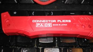
Handles
Handles

The rubber handles are press-fit onto the steel frame arms of the pliers, and don’t slip off readily.

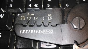
Die Head
Die Head

The dies are well formed in the steel, and seem to be machined rather than stamped on a press, however the black oxide finish hides any machining marks. The smallest 1mm dies do seem to be a little fragile as they’re so small, so wouldn’t take much abuse without shearing off.

Crimped Molex KK Pin

Here’s a Molex KK pin that’s been crimped with the PA-09. The insulation crimp has pierced the insulation slightly, but this isn’t much of a problem. The conductor crimp is nice & tight, and everything is small enough to fit correctly into the plastic connector body. The trick with these tools is getting a feel for when the crimp is done – squeeze too tightly & the contact deforms, not tightly enough & the wire will just pull out of the terminal. The official tools also crimp both the conductor & insulation at the same time, and they also hold the terminal in place while the wire is inserted. In these cheaper tools, the crimps are done separately, but they do hold on to the contact securely enough for the wire to be inserted properly with your spare hand.

Posted on Leave a comment

nb Tanya Louise Heating System – Oxide Sludge

I wrote a few weeks ago about replacing the hot water circulating pump on the boat with a new one, and mentioned that we’d been through several pumps over the years. After every replacement, autopsy of the pump has revealed the failure mode: the first pump failed due to old age & limited life of carbon brushes. The second failed due to thermal shock from an airlock in the system causing the boiler to go a bit nuts through lack of water flow. The ceramic rotor in this one just cracked.
The last pump though, was mechanically worn, the pump bearings nicely polished down just enough to cause the rotor to stick. This is caused by sediment in the system, which comes from corrosion in the various components of the system. Radiators & skin tanks are steel, engine block cast iron, back boiler stainless steel, Webasto heat exchanger aluminium, along with various bits of copper pipe & hose tying the system together.
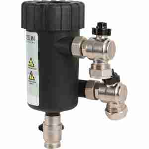
The use of dissimilar metals in a system is not particularly advisable, but in the case of the boat, it’s unavoidable. The antifreeze in the water does have anti-corrosive additives, but we were still left with the problem of all the various oxides of iron floating around the system acting like an abrasive. To solve this problem without having to go to the trouble of doing a full system flush, we fitted a magnetic filter:

Mag Filter
Mag Filter

This is just an empty container, with a powerful NdFeB magnet inserted into the centre. As the water flows in a spiral around the magnetic core, aided by the offset pipe connections, the magnet pulls all the magnetic oxides out of the water. it’s fitted into the circuit at the last radiator, where it’s accessible for the mandatory maintenance.

Sludge
Sludge

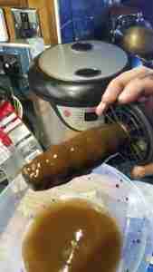
Now the filter has been in about a month, I decided it would be a good time to see how much muck had been pulled out of the circuit. I was rather surprised to see a 1/2″ thick layer of sludge coating the magnetic core! The disgusting water in the bowl below was what drained out of the filter before the top was pulled. (The general colour of the water in the circuit isn’t this colour, I knocked some loose from the core of the filter while isolating it).

If all goes well, the level of sludge in the system will over time be reduced to a very low level, with the corrosion inhibitor helping things along. This should result in much fewer expensive pump replacements!

He-Ne Laser Safety

As with *any* laser, proper precautions must be taken to avoid any possibility of damage to vision. The types of He-Ne lasers mostly dealt with in this document are rated Class II, IIIa, or the low end of IIIb (see the section: Laser Safety Classifications. For most of these, common sense (don’t stare into the beam) and fairly basic precautions suffice since the reflected or scattered light will not cause instantaneous injury and is not a fire hazard.

However, unlike those for laser diodes, He-Ne power supplies utilize high voltage (several kV) and some designs may be potentially lethal. This is particularly true of AC line powered units since the power transformer may be capable of much more current than is actually required by the He-Ne laser tube – especially if it is home built using the transformer from some other piece of equipment (like an old tube type console TV or that utility pole transformer you found along the curb) which may have a much higher current rating.

The high quality capacitors in a typical power supply will hold enough charge to wake you up – for quite a while even after the supply has been switched off and unplugged. Depending on design, there may be up to 10 to 15 kV or more (but on very small capacitors) if the power supply was operated without a He-Ne tube attached or it did not start for some reason. There will likely be a lower voltage – perhaps 1 to 3 kV – on somewhat larger capacitors. Unless significantly oversized, the amount of stored energy isn’t likely to be enough to be lethal but it can still be quite a jolt. The He-Ne tube itself also acts as a small HV capacitor so even touching it should it become disconnected from the power supply may give you a tingle. This probably won’t really hurt you physically but your ego may be bruised if you then drop the tube and it then shatters on the floor!

However, should you be dealing with a much larger He-Ne laser, its power supply is going to be correspondingly more dangerous as well. For example, a 35 mW He-Ne tube typically requires about 8 mA at 5 to 6 kV. That current may not sound like much but the power supply is likely capable of providing much more if you are the destination instead of the laser head (especially if it is a home-made unit using grossly oversized parts)! It doesn’t take much more under the wrong conditions to kill.

After powering off, use a well insulated 1M resistor made from a string of ten 100K, 2 W metal film resistors in a glass or plastic tube to drain the charge – and confirm with a voltmeter before touching anything. (Don’t use carbon resistors as I have seen them behave funny around high voltages. And, don’t use the old screwdriver trick – shorting the output of the power supply directly to ground – as this may damage it internally.)

And only change electrical connections or plug/unplug connectors with power OFF, being aware of the potential for stored charge. In particular, the aluminium cylinder of some HeNe laser heads is the negative return for the tube current via a spring contact inside the rear end-cap. So, pulling off the rear end-cap while the laser is powered will likely make YOU the negative return instead! You will probably then bounce off the ceiling while the laser bounces off the floor, which can easily ruin your entire day in more ways than one. 🙁 🙂 This connection scheme is known to be true for most JDS Uniphase and many Melles Griot laser heads, but may apply to others as well.

Now, for some first-hand experience:

(From: Doug (dulmage@skypoint.com).)

Well, here’s where I embarrass myself, but hopefully save a life…

I’ve worked on medium and large frame lasers since about 1980 (Spectra-Physics 168’s, 171’s, Innova 90’s, 100’s and 200’s – high voltage, high current, no line isolation, multi-kV igniters, etc.). Never in all that time did I ever get hurt other than getting a few retinal burns (that’s bad enough, but at least I never fell across a tube or igniter at startup). Anyway, the one laser that almost did kill me was also the smallest that I ever worked on.

I was doing some testing of AO devices along with some small cylindrical HeNe tubes from Siemens. These little coax tubes had clips for attaching the anode and cathode connections. Well, I was going through a few boxes of these things a day doing various tests. Just slap them on the bench, fire them up, discharge the supplies and then disconnect and try another one. They ran off a 9 VDC power supply.

At the end of one long day, I called it quits early and just shut the laser supply off and left the tube in place as I was just going to put on a new tube in the morning. That next morning, I came and incorrectly assumed that the power supply would have discharged on it own overnight. So, with each hand I stupidly grab one clip each on the laser to disconnect it. YeeHaaaaaaaaa!!!!. I felt like I had been hid across my temples with a two by four. It felt like I swallowed my tongue and then I kind of blacked out. One of the guys came and helped me up, but I was weak in the knees, and very disoriented.

I stumbled around for about 15 minutes and then out of nowhere it was just like I got another shock! This cycle of stuff went on for about 3 hours, then stopped once I got to the hospital. I can’t even remember what they did to me there. Anyway, how embarrassing to almost get killed by a HeNe laser after all that other high power stuff that I did. I think that’s called ‘irony’.

Comments on HeNe Laser Safety Issues

(Portions from: Robert Savas (jondrew@mail.ao.net).)

A 10 mw HeNe laser certainly presents an eye hazard.

According to American National Standard, ANSI Z136.1-1993, table 4 Simplified Method for Selecting Laser Eye Protection for Intrabeam Viewing, protective eyewear with an attenuation factor of 10 (Optical Density 1) is required for a HeNe with a 10 milliwatt output. This assumes an exposure duration of 0.25 to 10 seconds, the time in which they eye would blink or change viewing direction due the uncomfortable illumination level of the laser. Eyeware with an attenuation factor of 10 is roughly comparable to a good pair of sunglasses (this is NOT intended as a rigorous safety analysis, and I take no responsibility for anyone foolish enough to stare at a laser beam under any circumstances). This calculation also assumes the entire 10 milliwatts are contained in a beam small enough to enter a 7 millimeter aperture (the pupil of the eye). Beyond a few meters the beam has spread out enough so that only a small fraction of the total optical power could possible enter the eye.
Posted on Leave a comment

Boating: Drydock Time – New Running Gear & Rudder Modifications

New Shaft & Prop
New Shaft & Prop

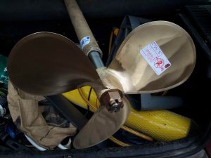
We’re now on the final leg of the jobs to be done on the boat! Above is the new prop & shaft, supplied to us by Crowther Marine over in Royton. To fit our current stern tube & gland, the shaft is the same diamter at 1-3/8″. Unfortunately no 4-blade props were available, so I had to go for a 17×11 left-hand, but with a much larger blade area than the old one.

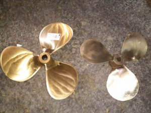
Propellers
Propellers

Here’s the old prop on the right, with the new one on the left, amazing how different 1 inch of diameter actually looks. The opposite hand of the new prop makes no difference in our case, as I can simply switch the hoses to the hydraulic motor on the shaft to make everything reverse direction.

Stripper
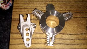
Stripper

Above is the solution to my problem of no weed hatch – a Stripper Rope Cutter from Ambassador Marine. This device has some seriously viciously sharp cutting teeth to help clear any fouling from the prop in operation. Only time will tell if it’s effective at allowing me to stay out of the canal manually removing the crap!

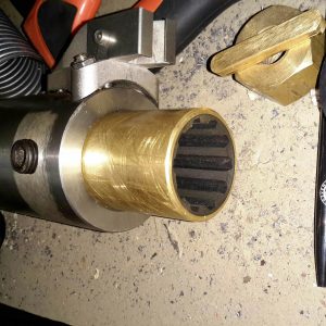
Cutless Bearing
Cutless Bearing

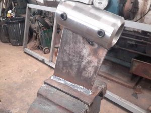
We finally got the bearing mount finished, by S Brown Engineering in Stockport. This is made from Stainless steel to stop the bearing corroding in place & becoming a real arse to replace. Set screws are fitted to make sure the bearing doesn’t move in service.
Attached to the side of the bearing housing is the fixed blade mounting for the Stripper Rope Cutter.

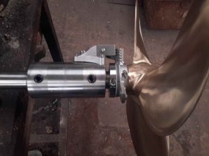
Bearing Test Fit
Bearing Test Fit

Above is everything fitted to the shaft for a test before the gear went into it’s home in the stern tube. The Stripper mounts behind the prop, clamped to the shaft. The 3 moving blades move against the fixed blade like a mechanised pair of scissors.

Bearing Strut Welding

10mm steel plate has been used to make the strut for the bearing tube, welded together. In the case of the joint between the stainless tube & the carbon steel strut, special welding rods were needed, at the price of £2 a rod! Using mild steel rods to weld stainless could result in cracking of the welds. Not a good thing on a prop shaft support bearing.

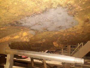
Sand Blasted Hull
Sand Blasted Hull

Most of the old tube has been cut away to make room for the new bearings, and the bottom of the hull has been sand-blasted ready for welding.

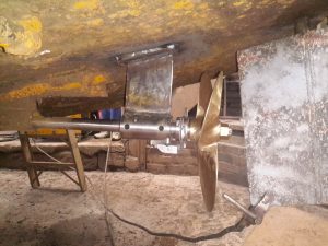
Running Gear Mounted

The bearing mount is welded to the hull, the Stripper & the prop are fitted to the end of the shaft. There’s 1.5″ of clearance from the blade tips to the hull plating. The rudder has about an inch of clearance to the end of the shaft.

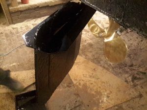
Rudder Fence
Rudder Fence

To help keep the prop wash down, directing more of the force into moving the vessel rather than creating a nice rooster tail, a pair of plates has been welded onto the rudder. These also provide a handy step should someone fall in ;).

Posted on Leave a comment

DIY Eberspacher Glowplug Screens: Recap

A while ago I posted about the glowplug screens in Eberspacher heaters, and making some DIY ones, as the OEM parts are hideously expensive for a piece of stainless mesh (£13).

Old Screen
Old Screen

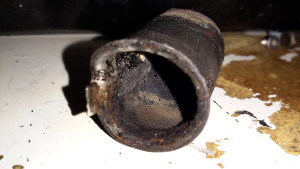
Above is the old factory screen that I extracted after only 5 gallons of diesel was run through it, it’s heavily clogged up with carbon & tar. The result of this clogging is a rather slow & smoky start of the heater & surging of the burner while at full power.
It wasn’t as badly stuck in the chamber as some I’ve removed, but extracting it still caused the steel ring to deform, this was after using a scalpel blade to scrape the carbon off the rim.

At the time I did some tests with some spare copper mesh I had to hand, but the problem with copper is that it’s very soft & malleable, so didn’t really hold it’s shape well enough. The factory screens are spot welded to keep them in shape, but as I don’t have a spot welder, I am relying on the mesh having a bit of springiness to keep it in place against the walls of the glowplug chamber.

eBay provided a piece of 120 mesh stainless steel mesh, 300mmx300mm for £8. It’s a bit finer than the stock stuff, but appears to work perfectly fine as long as there’s no gunk in the fuel to clog it up.

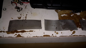
I cut a strip off the large piece, as wide as the OEM screen, about 32mm. This 300mm long strip is then cut into 4 pieces, each 75mm long. (it’s easily cut with scissors, but mind the stray wires on the edges! They’re very sharp & penetrate skin easily!).

Mesh Screen
Mesh Screen

These pieces are just the right size to form a complete loop in the glowplug chamber, and the stainless is springy enough so that it doesn’t deform & become loose.
The OEM screen is multiple turns of a more coarse mesh, but the finer mesh size of the screens I’m using means only one turn is required. Multiple turns would probably be too restrictive to fuel flow.
With one of these pieces of mesh in place, the heater starts instantly, without even a wisp of smoke from the exhaust. Burner surging is also eliminated. Even if the service life of my DIY replacement isn’t as long as an OEM screen, the low price for such a large number of replacements certainly offsets that disadvantage!

A piece of mesh from eBay would provide enough material for quite a lot of replacements, and probably more than the service life of the burner itself!

Posted on 7 Comments

Monox Compact-S CO Sensor Cell

Top
Top

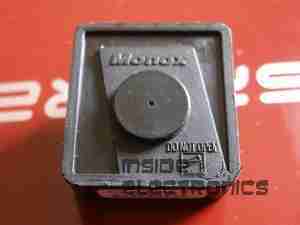
Here is an old electrochemical type carbon monoxide detector cell, from Monox. Hole in the centre is the inlet for the gas under test.
DO NOT TRY THIS AT HOME! Electrochemical cells contain a substantial amount of sulphuric acid, strong enough to cause burns.

This is a type of fuel cell that instead of being designed to produce power, is designed to produce a current that is precisely related to the amount of the target gas (in this case carbon monoxide) in the atmosphere. Measurement of the current gives a measure of the concentration of carbon monoxide in the atmosphere. Essentially the electrochemical cell consists of a container, 2 electrodes, connection wires and an electrolyte – typically sulfuric acid. Carbon monoxide is oxidized at one electrode to carbon dioxide while oxygen is consumed at the other electrode. For carbon monoxide detection, the electrochemical cell has advantages over other technologies in that it has a highly accurate and linear output to carbon monoxide concentration, requires minimal power as it is operated at room temperature, and has a long lifetime (typically commercial available cells now have lifetimes of 5 years or greater). Until recently, the cost of these cells and concerns about their long term reliability had limited uptake of this technology in the marketplace, although these concerns are now largely overcome. This technology is now the dominant technology in USA and Europe.

Rear
Rear

Rear of unit with connection pins. Hole here is to let oxygen into the cell which permits the redox reaction to take place in the cell when CO is detected, producing a voltage on the output pins.

Disassembled
Disassembled

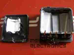
Cell disassembled. The semi-permeable membrane on the back cover can be seen here, to allow gas into the cell, but not the liquid electrolyte out. Cell with the electrodes is on the right, immersed in sulphuric acid.

Platinum Electrode
Platinum Electrode

Closeup of the electrode structure. Polymer base with a precious metal coating.

Membrane
Membrane

Membrane & filter on the test gas input port.

Posted on Leave a comment

Dremel MultiPro

Front
Front

Here we have a Dremel MultiPro rotary tool, a main powered 125W 33,000RPM bit of kit.

Motor Assembly
Motor Assembly

Here the field & controller assembly is removed from the casing.

Armature
Armature

Here is the armature, which rotates at up to 33,000RPM. The brushes rise against the commutator on the left, next to the bearing, the cooling fan is on the right hand side on the power output shaft, the chuck attaches at the far right end of the shaft.

Speed Controller & Brush Box

Here is the speed controller unit, inside is an SCR phase angle speed controller, to vary the speed of the motor from 10,000RPM to the full rated speed of 33,000RPM.

Mains Filter
Mains Filter

This is the mains filter on the input to the unit, stops stray RF from the motor being radiated down the mains cable.