My other monitors are a different model, and have a slightly different main PCB inside, but the process is mostly the same for converting these to 12v supply.
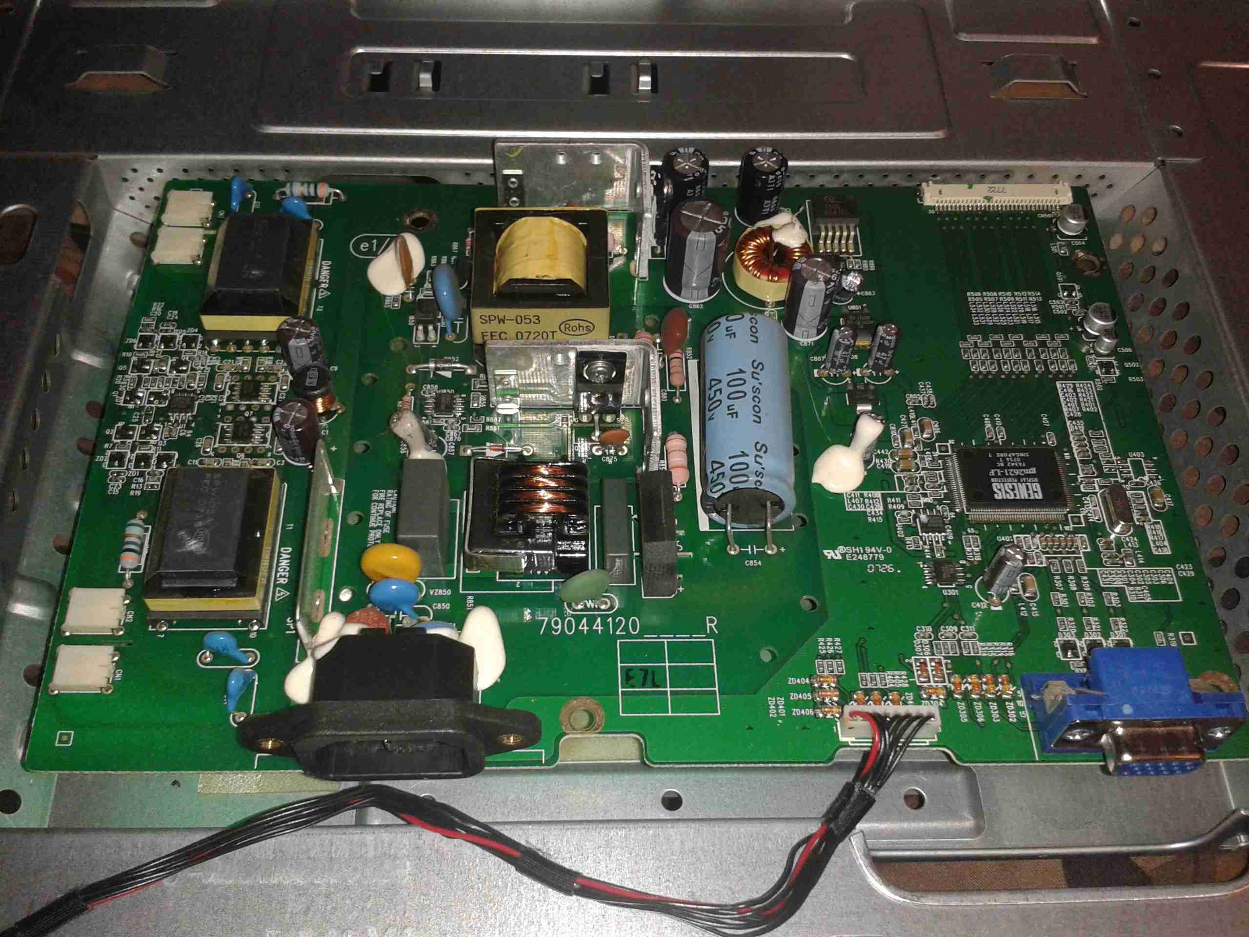
In this monitor type, there is only a single board, with all the PSU & logic, instead of separate boards for each function.
This monitor is slightly different in it’s power supply layout. The mains supply provides only a single 12v rail, which is then stepped down by a switching converter to 5v, then by smaller linear regulators to 3.3v & 1.8v for the logic. This makes my life easier since I don’t have to worry about any power conversion at all.
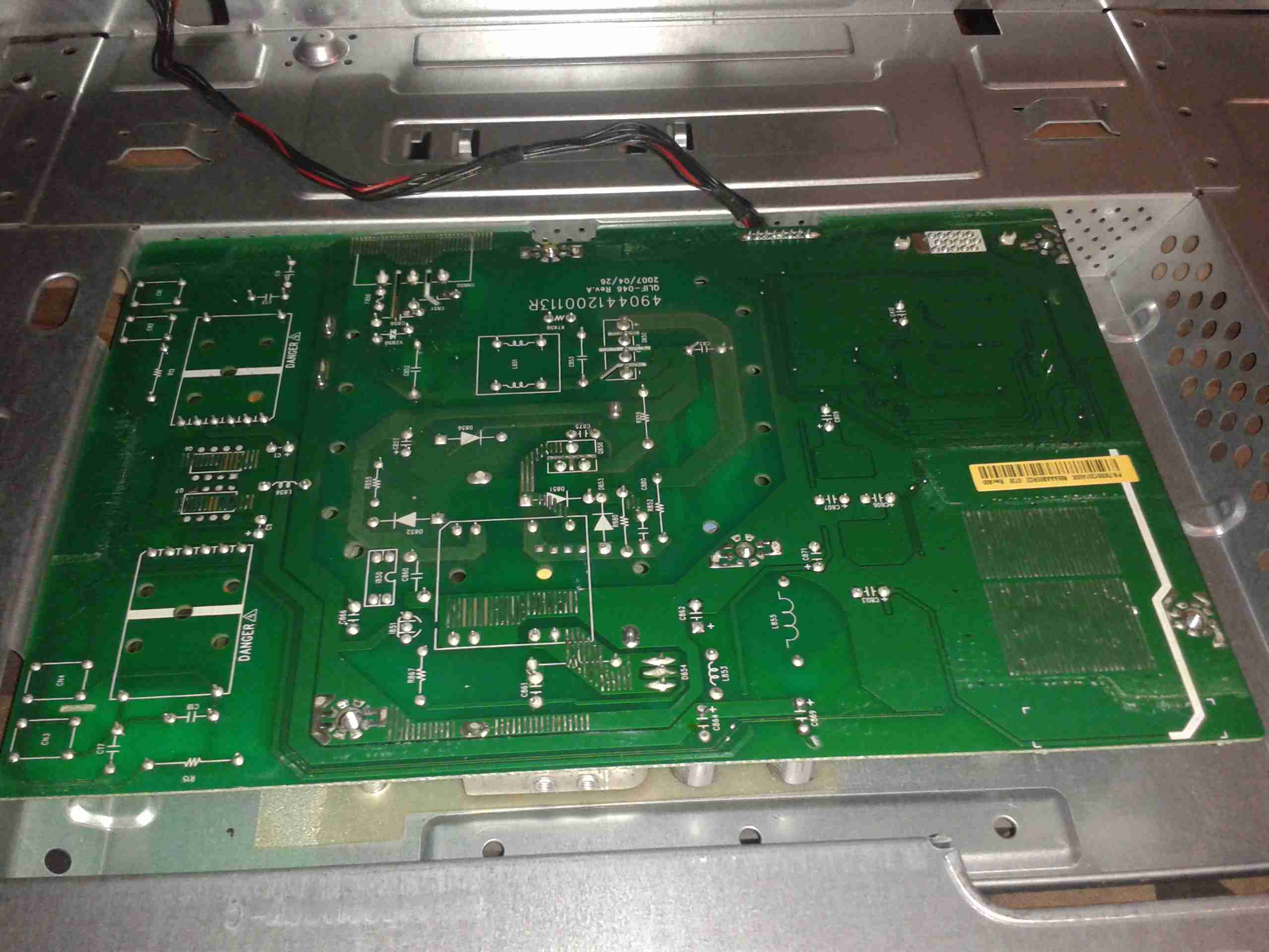
Here’s the backside of the PCB, the mains PSU section is in the centre.
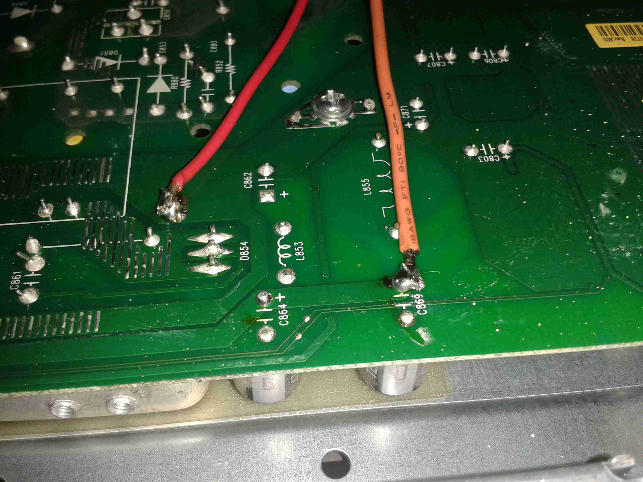
Here’s the pair of 12v supply wires soldered onto the main board, onto the common GND connection on the left, and the main +12v rail on the right. I’ve not bothered with colour coding the wiring here, just used whatever I had to hand that was heavy enough to cope with a couple amps.
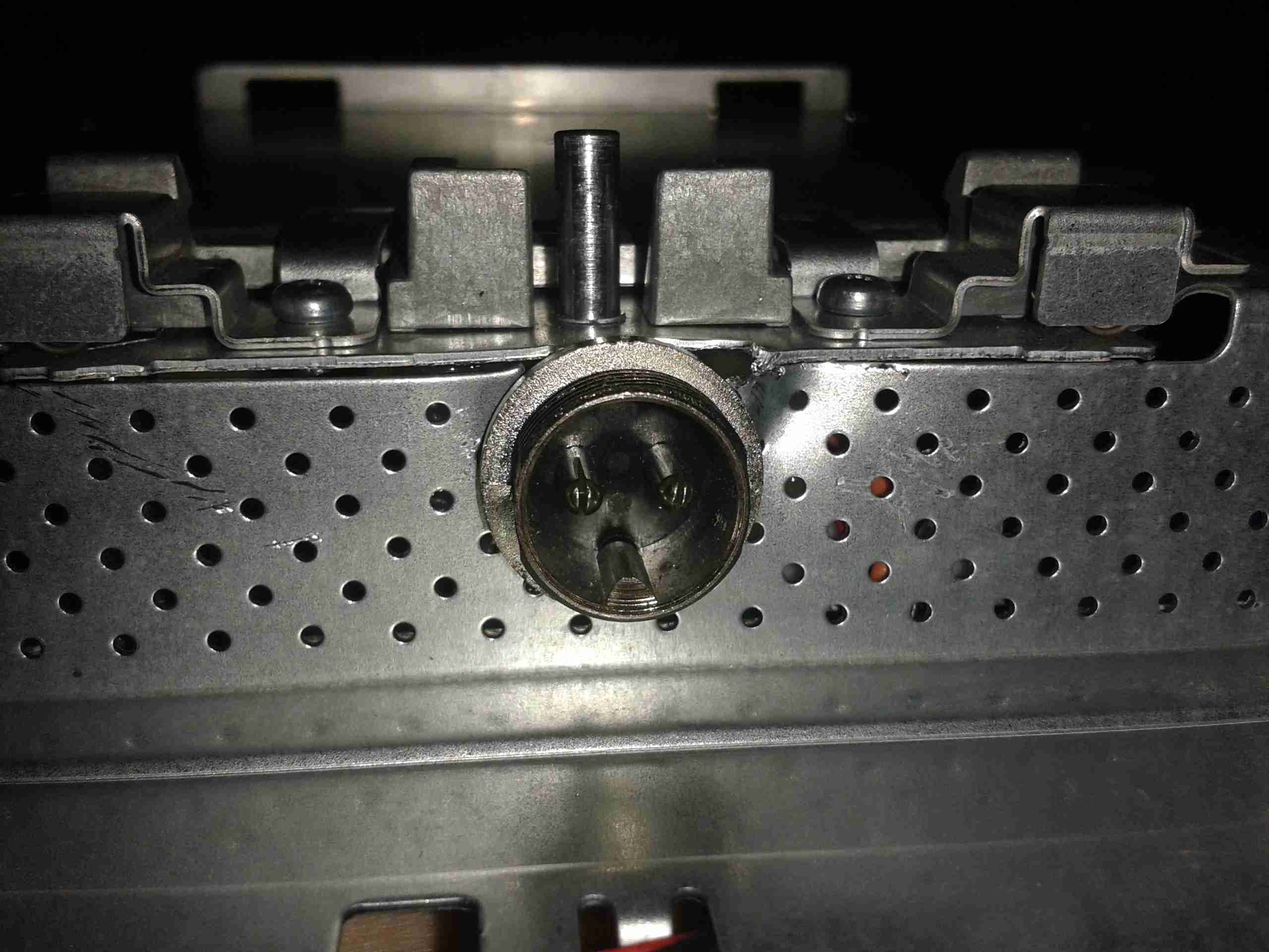
A small mod later with a cone drill & the 12v input socket is mounted in the LCD frame.
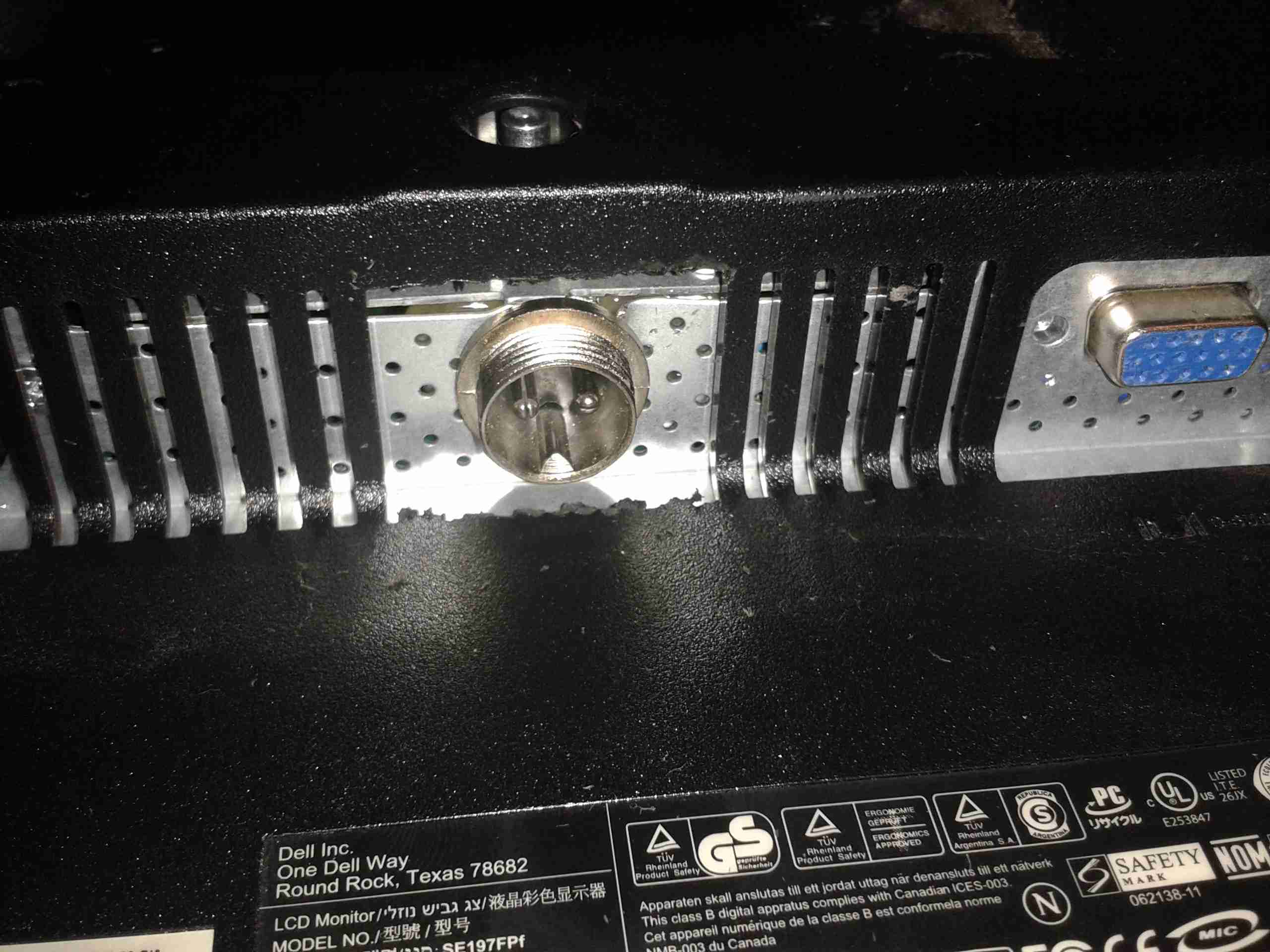
Some light removal of plastic & the back cover fits back on. Current draw at 13.8v is ~2A.
