Posted on Leave a comment

Is SMART Really Useful?

Being in technology for a long time, I have seen my fair share of disk failures. However I have never seen a single instance where SMART has issued a sufficient warning to backup any data on a failing disk. The following is an example of this in action.

Toshiba MQ01ABD050
Toshiba MQ01ABD050

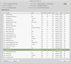
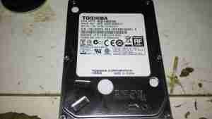
Here is a 2.5″ Toshiba MQ01ABD050 500GB disk drive. This unit was made in 2014, but has a very low hour count of ~8 months, with only ~5 months of the heads being loaded onto the platters, since it has been used to store offline files. This disk was working perfectly the last time it was plugged in a few weeks ago, but today within seconds of starting to transfer data, it began slowing down, then stopped entirely. A quick look at the SMART stats showed over 4000 reallocated sectors, so a full scan was initiated.

SMART Test Failure
SMART Test Failure

After the couple of hours an extended test takes, the firmware managed to find a total of 16,376 bad sectors, of which 10K+ were still pending reallocation. Just after the test finished, the disk began making the usual clicking sound of the head actuator losing lock on the servo tracks. Yet SMART was still insisting that the disk was OK! In total about 3 hours between first power up & the disk failing entirely. This is possibly the most sudden failure of a disk I’ve seen so far, but SMART didn’t even twig from the huge number of sector reallocations that something was amiss. I don’t believe the platters are at fault here, it’s most likely to be either a head fault or preamp failure, as I don’t think platters can catastrophically fail this quickly. I expected SMART to at least flag that the drive was in a bad state once it’s self-test completed, but nope.

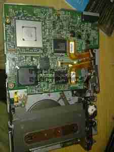
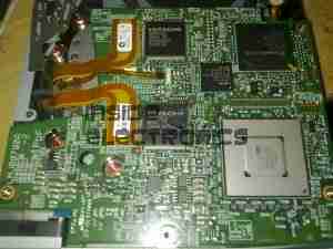
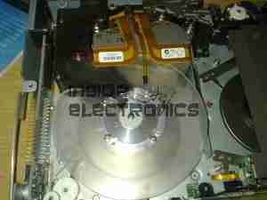
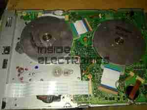
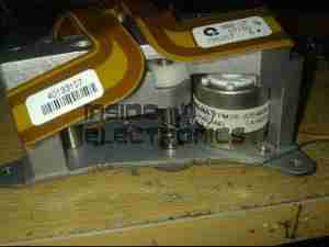
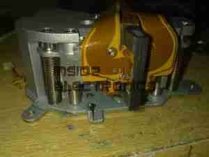
Internals
Internals

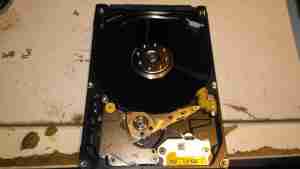
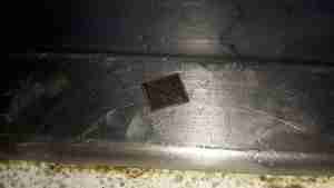
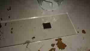
After pulling the lid on this disk, to see if there’s any evidence of a head crashing into a platter, there’s nothing – at least on a macroscopic scale, the single platter is pristine. I’ve seen disks crash to the point where the coating has been scrubbed from the platters so thoroughly that they’ve been returned to the glass discs they started off as, with the enclosure packed full of fine black powder that used to be data layer, but there’s no indication of mechanical failure here. Electronic failure is looking very likely.

Clearly, relying on SMART to alert when a disk is about to take a dive is an unwise idea, replacing drives after a set period is much better insurance if they are used for critical applications. Of course, current backups is always a good idea, no matter the age of drive.

Posted on 8 Comments

Contec CMS-50F Pulse Oximeter Teardown

Rear Case
Rear Case

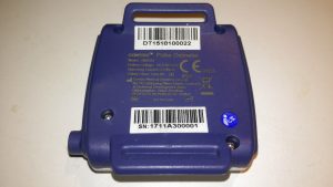
The rear has the specifications, laser-marked into the plastic. The serial numbers are just sticky labels though, and will come off easily with use.

Contec CMS-50F
Contec CMS-50F

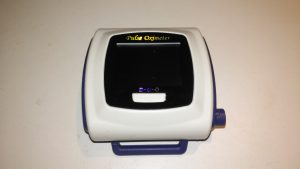
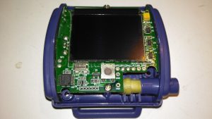
This is the Contec CMS-50F wrist-mounted pulse oximeter unit, which has the capability to record data continuously to onboard memory, to be read out at a later time via a USB-Serial link. There is software supplied with the unit for this purpose, although it suffers from the usual Chinese quality problems. The hardware of this unit is rather well made, the firmware has some niggles but is otherwise fully functional, however the PC software looks completely rushed, is of low quality & just has enough functionality to kind-of pass as usable.

Top Cover Removed
Top Cover Removed

A total of 4 screws hold the casing together, once these are removed the top comes off. The large colour OLED display covers nearly all of the board here. The single button below is the user interface. The connection to the probe is made via the Lemo-style connector on the lower right.

Lithium Cell
Lithium Cell

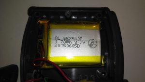
Power is provided by a relatively large lithium-ion cell, rated at 1.78Wh.

Main Processor
Main Processor

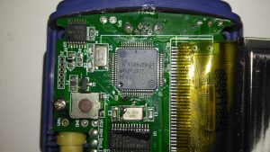
All the heavy lifting work of the LCD, serial comms, etc are handled by this large Texas Instruments microcontroller, a MSP430F247. The clock crystal is just to the left, with the programming pins. I’m not sure of the purpose of the small IC in the top left corner, I couldn’t find any reference to the markings.

Aux Processor
Aux Processor

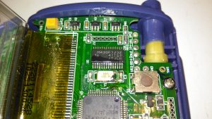
The actual pulse oximetry sensor readings seem to be dealth with by a secondary microcontroller, a Texas Instruments M430F1232 Mixed-Signal micro. This has it’s own clock crystal just underneath. The connections to the probe socket are to the right of this µC, while the programming bus is broken out to vias just above. The final devices on this side of the board are 3 linear regulators, supplying the rails to run all the logic in this device.

Main PCB Rear
Main PCB Rear

The rear of the PCB has the SiLabs CL2102 USB-Serial interface IC, the large Winbond 25X40CLNIG 512KByte SPI flash for recording oximetry data, and some of the power support components. The RTC crystal is also located here at the top of the board. Up in the top left corner is a Texas Instruments TPS61041 Boost converter, with it’s associated components. This is probably supplying the main voltage for the OLED display module.

Posted on 2 Comments

EpEver MT50 Control Panel Teardown

MT50 Control Panel
MT50 Control Panel

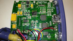
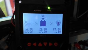
Here’s the MT50 controller from EpEver, that interfaces with it’s Tracer MPPT solar charge controllers, and gives access to more programming options on the charge controllers, without the need for a laptop. The display is a large dot-matrix unit, with built in backlight. Above is the display on the default page, showing power information for the entire system.

PCB Rear
PCB Rear

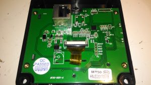
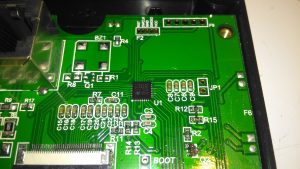
The rear plastic cover is held in place by 4 machine screws, which thread into brass inserts in the plastic frame – nice high quality touch on the design here, no cheap self tapping plastic screws. Both power & data arrive via an Ethernet cable, but the communication here is RS-485, and not compatible with Ethernet! The PCB is pretty sparse, with comms & power on the left, LCD connection in the centre, and the microcontroller on the right.

RS-485 Transceiver
RS-485 Transceiver

On the left of the board is the RS0485 transceiver, and a small voltage regulator. There’s also a spot for a DC barrel jack, which isn’t included in this model for local power supply.

STM32 Microcontroller

The other side of the board holds the main microcontroller which communicates with the charge controller. This is a STM32F051K8 from ST Microelectronics. With a 48MHz ARM Cortex M0 core, and up to 64K of flash, this is a pretty powerful MCU that has very little to do in this application.

PCB Front
PCB Front

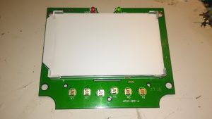
The front of the PCB has the ENIG contacts of the front panel buttons, and the LCD backlight assembly. There’s nothing else under the plastic backlight spreader either.

LCD Rear
LCD Rear

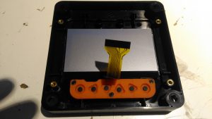
The front case holds the LCD module in place with glue, and the rubber buttons are placed underneath, which is heat staked in place.

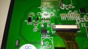
LCD Model
LCD Model

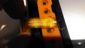
The LCD is a YC1420840CS6 from eCen in China. Couldn’t find much out about this specific LCD.

Posted on Leave a comment

Tenda S105 5-Port 10/100 Ethernet Switch

Top
Top

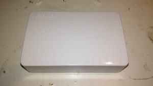
Here’s a tiny ethernet switch from the great fle market that is eBay – the Tenda S105. This unit has 5 ports, but only supports 10/100M. Still, for something so small it’s not bad.

Bottom
Bottom

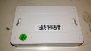
Not much on the bottom, there’s a pair of screw hooks for mounting this to a surface.

Ports
Ports

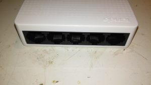
The 5 ports on the front actually have the pins for the unused pairs of the ethernet cables removed – saving every penny here.

PCB Top
PCB Top

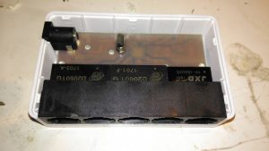
The casing just unclips, revealing the small PCB. Nothing much on the top, just the connectors, isolating transformers & the crystal for the switch IC.

PCB Bottom
PCB Bottom

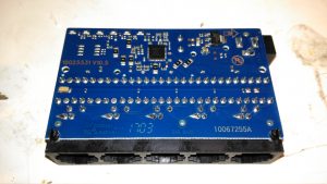
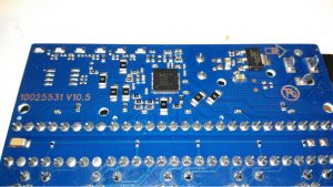
The bottom of the PCB is a little more busy, mainly with decoupling components. There’s a 3.3v linear regulator to step down the 5v input for the switch IC.

Switch IC
Switch IC

The IC doing all the data switching is an IP175G 5-Port 10/100 Switch from IC+ Corp. No datasheet available for this, but it’s going to be a bog-standard switch.

Posted on 2 Comments

STVG-502 Karaoke Machine CRT

Image Display

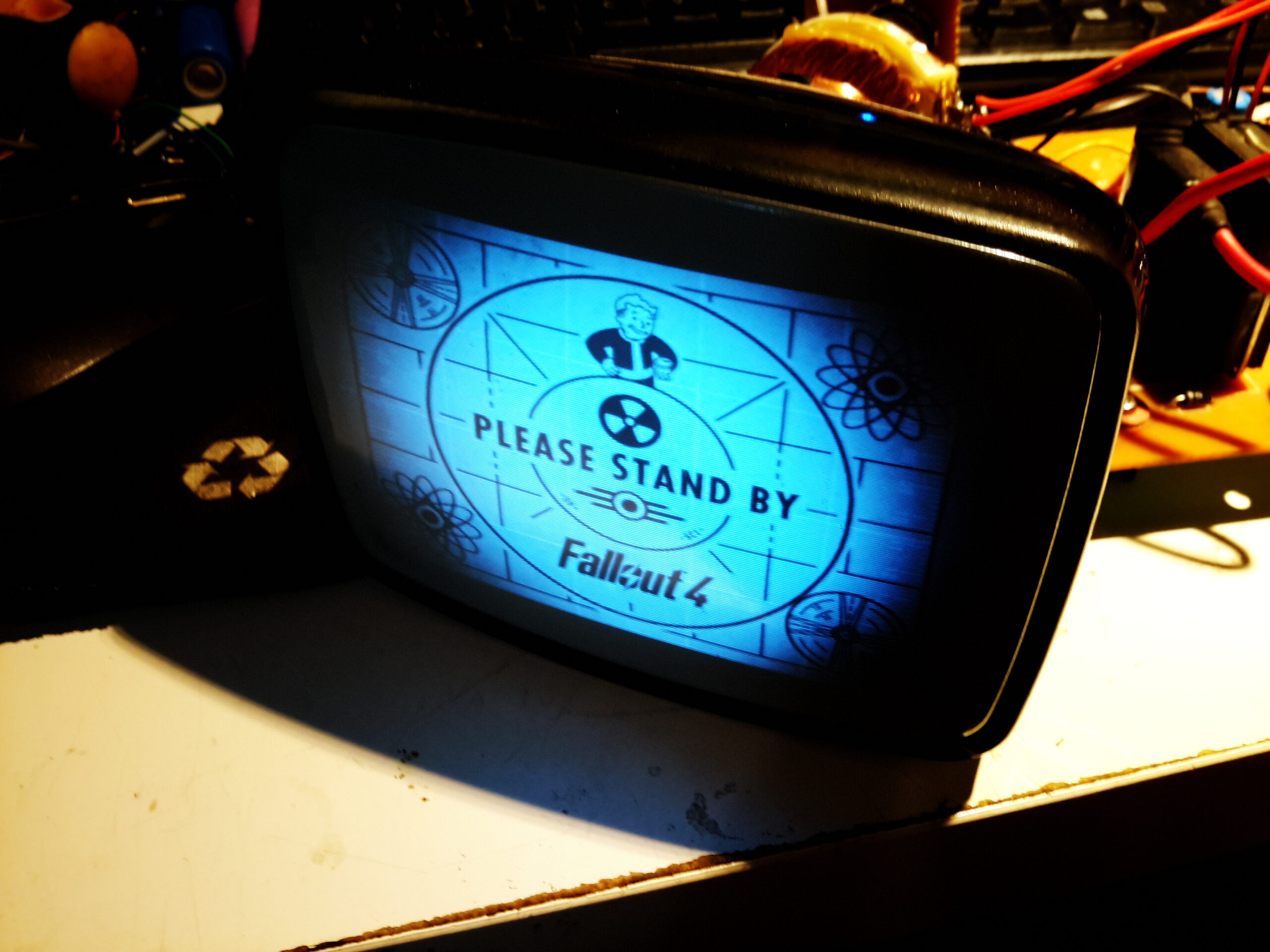
Here’s the CRT circuitry from a tossed STVG-502 Karaoke Machine, which got a good soaking in Manchester’s brilliantly wet weather before I managed to get hold of it:

Main PCB
Main PCB

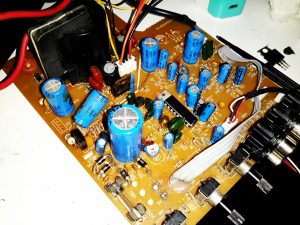
I didn’t do a full teardown of this unit, since it was soaking wet & smelled rather badly of sour milk, so instead I quickly gutted it for the useful parts. These machines are a combination of a CD+G player, CRT composite monitor for displaying the CD+G lyrics & a small audio amplifier & 3W speaker. Power is provided from the mains via a transformer, with both 12 & 24v windings. One half of the board has the audio amplifier sections, the other the CRT drive, running from the 12v & 24v supplies respectively. I chopped off the audio section, as that wasn’t needed.

Linear Regulator
Linear Regulator

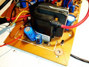
On this huge heatsink is what I originally thought was the horizontal drive transistor is actually a 12v linear regulator – the board gets fed 16v AC. This is then run through a rectifier which will produce an approx 22v rail, and after the smaller transistor on the left used for power switching. The 22v then gets dropped through a 1/2W 1Ω resistor, then the linear regulator drops it down to 12v for the rest of the circuit – dissipating a goodly amount of power in the process.

Horizontal Output Transistor

This is in fact the horizontal drive transistor, a 2SD613, which according to the datasheet, is intended for audio amplifier output stage applications, not CRT drive. Regardless, it’s an 85v 6A NPN transistor, and does get a bit on the warm side, but was never given a heatsink from the factory.

CRT Drive IC
CRT Drive IC

All the drive signals for the CRT are taken care of by this single DIP IC – a CD1379CP from Silicore. Considering the older CRT-based devices I have, with entire boards twice the size of this one dedicated to discrete components required to drive a CRT, this is definitely an advance in technology. Very few external components are being used, and no custom magnetics.

Video Input
Video Input

The video signal comes in from the CD+G player module on this connector, it’s a standard composite input. The composite video is fed into an amplifier after the controller IC. This video amp is powered from a 140v rail from the flyback transformer, to give enough signal to drive the CRT cathode.

LOPT
LOPT

The high voltage transformer is a BSH8-N5513L, I’ve not been able to find any data on this, but it looks like a standard off the shelf transformer from the listings on the Chinese supplier sites. There are very few support components around here, just a couple of diodes to rectify the high voltage focus supply, and no linearity coil. Weirdly, the 1st accelerating anode of the tube is grounded in this circuit. Very few adjustments are provided, most are set with fixed resistors to keep the cost low.

The CRT

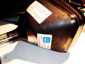
14SX3Y4 CRT
14SX3Y4 CRT

Here’s the CRT, it’s a 5″ monochrome model. I’ve not been able to find much data on this either.

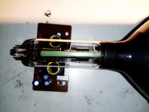
Bent Electron Gun
Bent Electron Gun

Seems the gents in the Shenzhen factory were having a bit of an off day when this one was made – the electron gun assembly is actually tilted in the neck of the tube – as a result the spot formed with no deflection is far from the centre of the screen. This tube does still produce a pretty good picture though, this manufacturing error is easily corrected for with the positioning magnets on the deflection yoke.

Final Mods

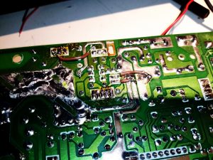
PCB Mods
PCB Mods

I’ve installed a couple of mod wires on the bottom of the PCB to get this to work outside the original application, without the room heater of a linear regulator in circuit this will run fine from a 12v supply. The PCB quality is a bit naff – even quick heating with a soldering iron makes tracks fall off the laminated paper board.

Image Display
Image Display

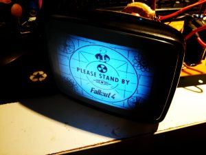
Image quality is surprisingly good for the cheapest CRT-based monitor I’ve ever seen, I figured a Fallout reference was required here; anyone for a proper CRT-based PipBoy? 😉 Shame the phosphor isn’t green.

Posted on Leave a comment

Blog Housekeeping & More Of The Same

Since I’ve been working on the backend servers a lot over the past few days, I’ve decided it was time to get some broken things on the blog fixed.

Firstly, the radiation monitor graphs. Originally I was using a Raspberry Pi to grab the data from the local monitor, and that was connecting via FTP to the server over in the datacentre to push it’s graph images. Since the server is now on the same local network as the monitor, there’s no need to faff about with FTP servers, so I’ve rejigged things with some perl scripts from cristianst85 over on GitHub, running on the web server itself.
I deviated from the suggested place to put the scripts on the server & opted to store everything within the Experimental Engineering hosting space, so it gets backed up at the same time as everything else on a nightly basis.

This is also accessible from the menu at top left, the script pulls data from the monitor & updates the images every 60 seconds via a cron job.

I’ve removed a couple of dead pages from the blog system, along with some backend tidying of the filesystem. Over the years things have gotten quite messy behind the scenes. This blog is actually getting quite large on disk, I’ve hit the 15GB mark, not including the database!

Caching is enabled for all posts on the blog now, this should help speed things up for repeat visitors, but as most of my content is (large) image based, this might be of limited help. I’m currently tuning the MySQL server for the load conditions, but this takes time, as every time I change some configuration settings I have to watch how things go for a few days, before tweaking some more.

Server Control Panels – More Of The Same

Sorry Sentora. I tried, and failed to convert over to using it as my new server control panel. Unfortunately it just doesn’t give me the same level of control over my systems, so I’ll be sticking with Virtualmin for the foreseeable future. Sentora stores everything in, (to me at least), very odd places under /var/ and gave me some odd results with “www.” versions of websites – some www. hosts would work fine, others wouldn’t at all & just redirect to the Sentora login interface instead. This wasn’t consistient between hosting accounts either, and since I didn’t have much time to get the migration underway, this problem was the main nail in the coffin.

Just storing everything under the sun in /var/ makes life a bit more awkward with the base CentOS install, as it allocates very little space to / by default, (no separate /var partition in default CentOS), giving most of the disk space to /home. Virtualmin on the other hand, stores website public files & Maildirs under /home, saving /var for MySQL databases & misc stuff.

The backup system provided is also utterly useless, there’s no restore function at all, and just piles everything in the account into a single archive. By comparison, Virtualmin has a very comprehensive backup system built in, that supports total automation of the process, along with full automatic restore functionality for when it’s needed.

Sentora did have some good points though:
It handled E-Mail logins & mail filters much more gracefully than Virtualmin does, and comes with Roundcube already built into the interface ready to use. With Virtualmin the options are to use the Usermin side of the system for E-Mail, which I find utterly awful to use, or install a webmail client under one of the hosted domains (my personal choice).
Mail filtering is taken care of with Sieve under Sentora, while Procmail does the job under Virtualmin.

Sentora does have a nicer, simpler, more friendly interface, but it hides most of the low-level system stuff away, while under Virtualmin *everything* on the system is accessible, and it provides control interfaces for all the common server daemons.

Posted on Leave a comment

Securing The New Server & Security In General

This was originally going to be part of another post, but it ended up getting more complex than I originally intended so it’s been given it’s own. I go into into many of my personal security practices, on both my public facing servers & personal machines. Since the intertubes are so central to life these days, good security is a must, especially since most people use the ‘net to do very sensitive operations, such as banking, it’s becoming even more essential to have strong security.

Since bringing the new server online & exposing it to the world, it’s been discovered in record time by the scum of the internet, SSH was under constant attack within 24 hours, and within that time there were over 20,000 failed login attempts in the logs.
This isn’t much of an issue, as I’ve got a strong Fail2Ban configuration running which at the moment is keeping track of some 30 IP addresses that are constantly trying to hammer their way in. No doubt these will be replaced with another string of attacks once they realise that those IPs are being dropped. I also prevent SSH login with passwords – RSA keys only here.
MySQL is the other main target to be concerned about – this is taken care of by disabling root login remotely, and dropping all MySQL traffic at the firewall that hasn’t come from 127.0.0.1.

Keeping the SSH keys on an external device & still keeping things simple just requires some tweaking to the .bashrc file in Linux:

alias ssh='ssh -i <Path To Keys>'

This little snippet makes the ssh client look somewhere else for the keys themselves, while keeping typing to a minimum in the Terminal. This assumes the external storage with the keys always mounts to the same location.

Everything else that can’t be totally blocked from outside access (IMAP, SMTP, FTP, etc), along with Fail2Ban protection, gets very strong passwords, unique to each account, (password reuse in any situation is a big no-no) and where possible TOTP-based two factor authentication is used for front end stuff, all the SSH keys, master passwords & backup codes are themselves kept offline, on encrypted storage, except for when they’re needed. General password management is taken care of by LastPass, and while they’ve been subject to a couple of rather serious vulnerabilities recently, these have been patched & it’s still probably one of the best options out there for a password vault.
There’s more information about those vulnerabilities on the LastPass blog here & here.


This level of security paranoia ensures that unauthorized access is made extremely difficult – an attacker would have to gain physical access to one of my mobile devices with the TOTP application, and have physical access to the storage where all the master keys are kept (along with it’s encryption key, which is safely stored in Meatware), to gain access to anything.
No security can ever be 100% perfect, there’s always going to be an attack surface somewhere, but I’ll certainly go as far as is reasonable, while not making my access a total pain, to keep that attack surface as small as possible,and therefore keeping the internet scum out of my systems.
The last layer of security is a personal VPN server, which keeps all traffic totally encrypted while it’s in transit across my ISP’s network, until it hits the end point server somewhere else in the world. Again, this isn’t perfect, as the data has to be decrypted *somewhere* along the chain.

Posted on Leave a comment

AIX Gigabit Ethernet To USB Bridge

USB To Ethernet
USB To Ethernet

Here’s a chap eBay USB-To-Ethernet dongle I obtained for use with the Raspberry Pi Zero. This one is getting torn down permanently, as it’s rather unreliable. It seems to like having random fits where it’ll not enumerate on the USB bus. The silicon in the ICs will eventually make it here once I manage to get a new microscope 😉

Main Chipset
Main Chipset

This is quite a heavily packed PCB, with the main Asix AX88178 on the left. This IC contains all of the logic for implementing the Ethernet link over USB, except the PHY. It’s clock crystal is in the top left corner.

Reverse Side
Reverse Side

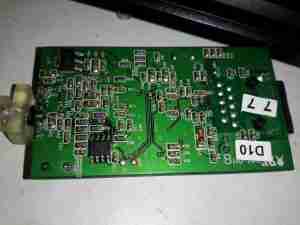
Not much on the reverse side, there’s a 3.3v linear regulator at top left, the SOIC is an Atmel AT93C66A 4KB EEPROM for configuration data.

Vitesse PHY
Vitesse PHY

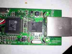
The final IC in the chain is the Vitesse VSC8211 Gigabit PHY, with it’s clock crystal below. This interfaces the Ethernet MAC in the Asix IC to the magjack on the right.

Posted on Leave a comment

eBay Special – LED Disco Light With Built In MP3 Player

Here’s an eBay oddity – it’s got the same light & lens mechanism as the cheap “disco light” style bulbs on eBay, but this one is battery powered & has a built in MP3 player.

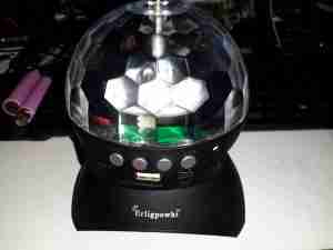
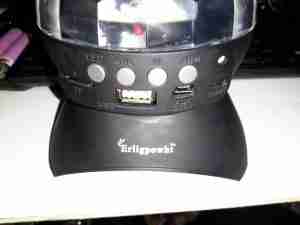
MP3 Disco Light
MP3 Disco Light

This device simply oozes cheapness. The large 4″ plastic dome lens sits on the top above the cheap plastic moulding as a base, which also contains the MP3 player speaker.

Controls
Controls

There are few controls on this player, the volume buttons are combined with the skip track buttons, a long press operates the volume control, while a short press skips the tracks. Several options for getting this thing to play music are provided:

  • Bluetooth – Allows connection from any device for bluetooth audio
  • USB – Plugging in a USB flash drive with MP3 files
  • SD Card – Very similar to the USB flash drive option, just a FAT32 formatted card with MP3 files
  • Aux – There’s no 3.5mm jack on this unit for an audio input, instead a “special” USB cable is supplied that is both used to charge the built in battery & feed an audio signal. This is possible since the data lines on the port aren’t used. But it’s certainly out of the ordinary.
Top Removed
Top Removed

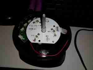
The top comes off with the removal of a single screw in the centre of the lens. The shaft in the centre that holds the lens is attached to a small gear motor under the LED PCB. There’s 6 LEDs on the board, to form an RGB array. Surprisingly for a very small battery powered unit these are bright to the point of being utterly offensive.

Mainboard
Mainboard

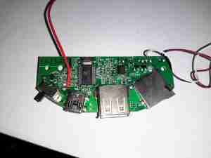
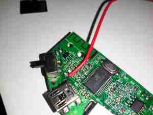
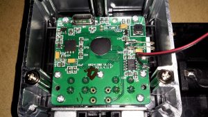
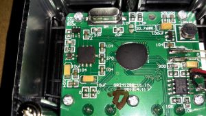
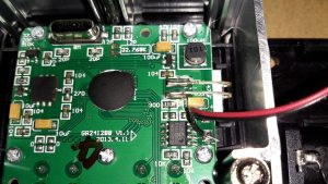
Here’s the mainboard removed from the plastic base. There’s not much to this device, even with all the options it has. The power switch is on the left, followed by the Mini-B USB charging port & aux audio input. The USB A port for a flash drive is next, finishing with the µSD slot. I’m not sure what the red wire is for on the left, it connects to one of the pins on the USB port & then goes nowhere.

Audio Amplifier
Audio Amplifier

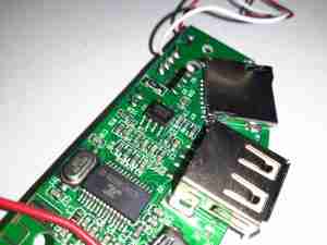
The audio amplifier is a YX8002D, I couldn’t find a datasheet for this, but it’s probably Class D.

Main Chipset
Main Chipset

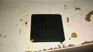
Finally there’s the main IC, which is an AC1542D88038. I’ve not been able to find any data on this part either, it’s either a dedicated MP3 player with Bluetooth radio built in, or an MCU of some kind.The RF antenna for the Bluetooth mode is at the top of the board.
Just behind the power switch is a SOT23-6 component, which should be the charger for the built in Lithium Ion cell.

Lithium Ion Cell
Lithium Ion Cell

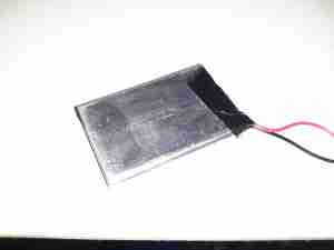
The cell itself is a prismatic type rated in the instructions at 600mAh, however my 1C discharge test gave a reading of 820mAh, which is unusual for anything Li-Ion based that comes from eBay 😉
There is cell protection provided, it’s under the black tape on the end, nothing special here.

The main issue so far with this little player is the utterly abysmal battery life – at full volume playing MP3s from a SD card, the unit’s current draw is 600mA, with the seizure & blindness-inducing LEDs added on top, the draw goes up to about 1200mA. The built in charger is also not able to keep up with running the player while charging. This in all only gives a battery life of about 20 minutes, which really limits the usability of the player.

Posted on Leave a comment

Project Volantis – Storage Server Rebuild

For some time now I’ve been running a large disk array to store all the essential data for my network. The current setup has 10x 4TB disks in a RAID6 array under Linux MD.

Up until now the disks have been running in external Orico 9558U3 USB3 drive bays, through a PCIe x1 USB3 controller. However in this configuration there have been a few issues:

  • Congestion over the USB3 link. RAID rebuild speeds were severely limited to ~20MB/s in the event of a failure. General data transfer was equally as slow.
  • Drive dock general reliability. The drive bays are running a USB3 – SATA controller with a port expander, a single drive failure would cause the controller to reset all disks on it’s bus. Instead of losing a single disk in the array, 5 would disappear at the same time.
  • Cooling. The factory fitted fans in these bays are total crap – and very difficult to get at to change. A fan failure quickly allows the disks to heat up to temperatures that would cause failure.
  • Upgrade options difficult. These bays are pretty expensive for what they are, and adding more disks to the USB3 bus would likely strangle the bandwidth even further.
  • Disk failure difficult to locate. The USB3 interface doesn’t pass on the disk serial number to the host OS, so working out which disk has actually failed is difficult.

To remedy these issues, a proper SATA controller solution was required. Proper hardware RAID controllers are incredibly expensive, so they’re out of the question, and since I’m already using Linux MD RAID, I didn’t need a hardware controller anyway.

16-Port HBA
16-Port HBA

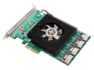
A quick search for suitable HBA cards showed me the IOCrest 16-port SATAIII controller, which is pretty low cost at £140. This card breaks out the SATA ports into standard SFF-8086 connectors, with 4 ports on each. Importantly the cables to convert from these server-grade connectors to standard SATA are supplied, as they’re pretty expensive on their own (£25 each).
This card gives me the option to expand the array to 16 disks eventually, although the active array will probably be kept at 14 disks with 2 hot spares, this will give a total capacity of 48TB.

HBA
SATA HBA

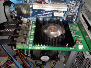
Here’s the card installed in the host machine, with the array running. One thing I didn’t expect was the card to be crusted with activity LEDs. There appears to be one LED for each pair of disks, plus a couple others which I would expect are activity on the backhaul link to PCIe. (I can’t be certain, as there isn’t any proper documentation anywhere for this card. It certainly didn’t come with any ;)).
I’m not too impressed with the fan that’s on the card – it’s a crap sleeve bearing type, so I’ll be keeping a close eye on this for failure & will replace with a high quality ball-bearing fan when it finally croaks. The heatsink is definitely oversized for the job, with nothing installed above the card barely gets warm, which is definitely a good thing for life expectancy.

Update 10/02/17 – The stock fan is now dead as a doornail after only 4 months of continuous operation. Replaced with a high quality ball-bearing 80mm Delta fan to keep things running cool. As there is no speed sense line on the stock fan, the only way to tell it was failing was by the horrendous screeching noise of the failing bearings.

SCSI Controller
SCSI Controller

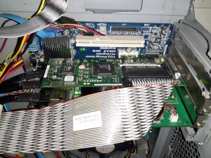
Above is the final HBA installed in the PCIe x1 slot above – a parallel SCSI U320 card that handles the tape backup drives. This card is very close to the cooling fan of the SATA card, and does make it run warmer, but not excessively warm. Unfortunately the card is too long for the other PCIe socket – it fouls on the DIMM slots.

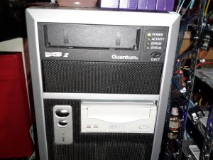
Backup Drives
Backup Drives

The tape drives are LTO2 300/600GB for large file backup & DDS4 20/40GB DAT for smaller stuff. These were had cheap on eBay, with a load of tapes. Newer LTO drives aren’t an option due to cost.

The main disk array is currently built as 9 disks in service with a single hot spare, in case of disk failure, this gives a total size after parity of 28TB:

/dev/md0:
        Version : 1.2
  Creation Time : Wed Mar 11 16:01:01 2015
     Raid Level : raid6
     Array Size : 27348211520 (26081.29 GiB 28004.57 GB)
  Used Dev Size : 3906887360 (3725.90 GiB 4000.65 GB)
   Raid Devices : 9
  Total Devices : 10
    Persistence : Superblock is persistent

  Intent Bitmap : Internal

    Update Time : Mon Nov 14 14:28:59 2016
          State : active 
 Active Devices : 9
Working Devices : 10
 Failed Devices : 0
  Spare Devices : 1

         Layout : left-symmetric
     Chunk Size : 64K

           Name : Main-PC:0
           UUID : 266632b8:2a8a3dd3:33ce0366:0b35fad9
         Events : 773938

    Number   Major   Minor   RaidDevice State
       0       8       48        0      active sync   /dev/sdd
       1       8       32        1      active sync   /dev/sdc
       9       8       96        2      active sync   /dev/sdg
      10       8      112        3      active sync   /dev/sdh
      11       8       16        4      active sync   /dev/sdb
       5       8      176        5      active sync   /dev/sdl
       6       8      144        6      active sync   /dev/sdj
       7       8      160        7      active sync   /dev/sdk
       8       8      128        8      active sync   /dev/sdi

      12       8        0        -      spare   /dev/sda

The disks used are Seagate ST4000DM000 Desktop HDDs, which at this point have ~15K hours on them, and show no signs of impending failure.

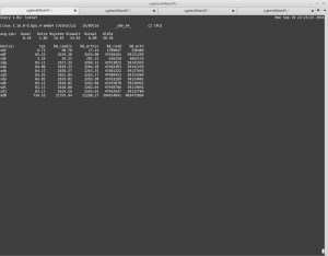
USB3 Speeds
USB3 Speeds

Here’s a screenshot with the disk array fully loaded running over USB3. The aggregate speed on the md0 device is only 21795KB/s. Extremely slow indeed.

This card is structured similarly to the external USB3 bays – a PCI Express bridge glues 4 Marvell 9215 4-port SATA controllers into a single x8 card. Bus contention may become an issue with all 16 ports used, but as far with 9 active devices, the performance increase is impressive. Adding another disk to the active array would certainly give everything a workout, as rebuilding with an extra disk will hammer both read from the existing disks & will write to the new.

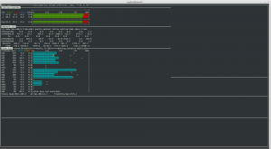
HBA Speeds
HBA Speeds

With all disks on the new controller, I’m sustaining read speeds of 180MB/s. (Pulling data off over the network). Write speeds are always going to be pretty pathetic with RAID6, as parity calculations have to be done. With Linux MD, this is done by the host CPU, which is currently a Core2Duo E7500 at 2.96GHz, with this setup, I get 40-60MB/s writes to the array with large files.

Disk Array
Disk Array

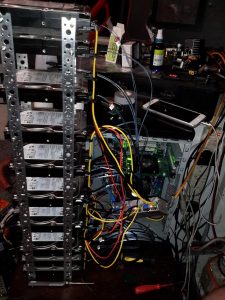
Since I don’t have a suitable case with built in drive bays, (again, they’re expensive), I’ve had to improvise with some steel strip to hold the disks in a stack. 3 DC-DC converters provides the regulated 12v & 5v for the disks from the main unregulated 12v system supply. Both the host system & the disks run from my central battery-backed 12v system, which acts like a large UPS for this.

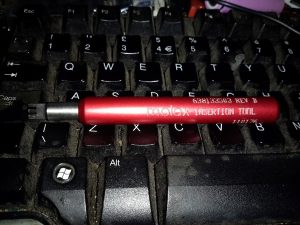
The SATA power splitters were custom made, the connectors are Molex 67926-0001 IDC SATA power connectors, with 18AWG cable to provide the power to 4 disks in a string.

IDT Insertion Tool
IDT Insertion Tool

These require the use of a special tool if you value your sanity, which is a bit on the expensive side at £25+VAT, but doing it without is very difficult. You get a very well made tool for the price though, the handle is anodised aluminium & the tool head itself is a 300 series stainless steel.

Posted on Leave a comment

OLED Pulse Oximeter Teardown

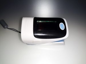
OLED Pulse Oximeter
OLED Pulse Oximeter

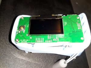
Here’s a piece of medical equipment that in recent years has become extremely cheap, – a Pulse Oximeter, used to determine the oxygen saturation in the blood. These can be had on eBay for less than £15.

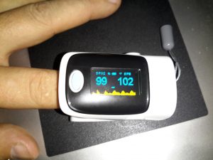
Powered On
Powered On

This one has a dual colour OLED display, a single button for powering on & adjusting a few settings. These cheap Oximeters do have a bit of a cheap plastic feel to them, but they do seem to work pretty well.

Pulse Oximeter
Pulse Oximeter

After a few seconds of being applied to a finger, the unit gives readings that apparently confirm that I’m alive at least. 😉 The device takes a few seconds to get a baseline reading & calibrate the sensor levels.

Main PCB Top
Main PCB Top

The plastic casing is held together with a few very small screws, but comes apart easily. here is the top of the main board with the OLED display panel. There appears to be a programming header & a serial port on the board as well. I’ll have to poke at these pads with a scope to see if any useful data is on the pins.

Main PCB Bottom
Main PCB Bottom

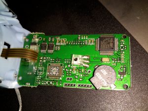
The bottom of the board has all the main components of the system. The microcontroller is a STM32F03C8T6, these are very common in Chinese gear these days. There’s a small piezo beeper & the main photodiode detector is in the centre.
There is an unpopulated IC space on the board with room for support components. I suspect this would be for a Bluetooth radio, as there’s a space at the bottom left of the PCB with no copper planes – this looks like an antenna mounting point. (The serial port on the pads is probably routed here, for remote monitoring).
At the top left are a pair of SGM3005 Dual SPDT analogue switches. These will be used to alternate the red & IR LEDs on the other side of the shell.
A 4-core FFC goes off to the other side of the shell, bringing power from the battery & supplying the sensing LEDs.

Battery Compartment
Battery Compartment

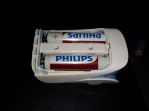
Power is supplied by a pair of AAA cells in the other shell.

Dual LED
Dual LED

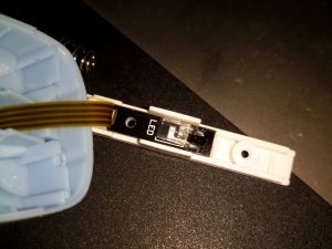
The sensor LEDs are tucked in between the cells, this dual-diode package has a 660nm red LED & a 940nm IR LED.

Viewing Spectral Lines in Discharge, Other Colours in Output

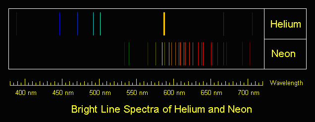
For accurate measurements, you’ll need an optical instrument such as a monochromator or spectrophotometer or optical spectrum analyzer. But to simply see the complexity of the discharge spectrum inside the bore of a He-Ne laser tube, it’s much easier and cheaper.

(Spectra for various elements and compounds can be easily found by searching the Web. The NIST Atomic Spectra Database has an applet which will generate a table or plot of more spectral lines than you could ever want.)

Instant Spectroscope for Viewing Lines in He-Ne Discharge

It is easy to look at the major visible lines. All it takes is a diffraction grating or prism. I made my instant spectroscope from the diffraction grating out of some sort of special effects glasses – found in a box of cereal, no less! – and a monocular (actually 1/2 of a pair of binoculars).

  • If you missed the Kellogg’s option, diffraction gratings can be purchased from places like Edmund Scientific. You don’t need anything fancy – any of the inexpensive ‘transmission replica gratings’ on a flat rigid substrate or mounted between a pair of plane glass plates will be fine. In a pinch, a CD disc or other optical media will work but only as a reflection grating so mounting may be a problem. A spectroscope can also be made with a prism of course but a diffraction grating is likely to be less expensive and better for this application since it is much lighter and easier to mount.
  • The plasma tube of a bare He-Ne laser is an ideal light source since it provides its own slit as the glow discharge is confined to the long narrow capillary bore. However, this approach can also be used with other lasers as long as the beam can be focused to a spot on a wall or screen. This will produce a ‘bright spot spectra’ instead of politically correct lines but you can’t have everything. 🙂
  • The diffraction grating can be used by itself but the additional optics will provide magnification and other benefits for people with less than perfect eyeballs.
  • Glue the diffraction grating to a cardboard sleeve that can be slipped over the (or one) objective of a monocular, binocular, or small telescope – or the telephoto lens of your camera. Orient it so that the dispersion will be vertical (since your slit will be horizontal).
  • Operate the HeNe tube on a piece of black velvet or paper. This will result in optimum contrast. This is best done in a darkened room where the only source of light is the laser tube itself. Just don’t trip and zap yourself on the high voltage!
  • A diffraction grating produces several images. The zero’th order will be the original image seen straight ahead. The important ones are the first order spectra. Tip the instrument up or down to see these. The dispersion direction – order of the colours – will depend on which way it is tipped.
  • Any distance beyond the closest focus of your instrument will work but being further away will reduce the effective width of the ‘slit’ resulting in the ability to distinguish more closely spaced lines.

The shear number of individual spectral lines present in the discharge is quite amazing. You will see the major red, orange, yellow, and green lines as well as some far into the blue and violet portions of the spectrum and toward the IR as well.

Bright Line Spectra of Helium and Neon

All of those shown will be present as well as many others not produced by the individual gas discharges. There are numerous IR lines as well but, of course, these will not be visible.

Place a white card in the exit beam and note where the single red output line of the He-Ne tube falls relative to the position and intensity of the numerous red lines present in the gas discharge.

As an aside, you may also note a weak blue/green haze surrounding the intense main red beam (not even with the spectroscope). This is due to the blue/green (incoherent) spectral lines in the discharge being able to pass through the output mirror which has been optimized to reflect well (>99 percent) at 632.8 nm and is relatively transparent at wavelengths some distance away from these (shorter and longer but you would need an IR sensor to see the longer ones). Since it is not part of the lasing process, this light diverges rapidly and is therefore only visible close to the tube’s output mirror.

Dynamic Measurement of Discharge Spectra

The following is trivial to do if you have a recording spectrometer and external mirror He-Ne laser. For an internal mirror He-Ne laser tube, it should be possible to rock one of the mirrors far enough to kill lasing without permanently changing alignment. If you don’t have proper measuring instruments, don’t worry, this is probably in the “Gee wiz, that’s neat but of marginal practical use” department. 🙂

(From: George Werner (glwerner@sprynet.com).)

Here is an effect I found many years ago and I don’t know if anyone has pursued it further.

We had a recording spectrometer in our lab which we used to examine the incoherent light coming from the laser discharge. This spectrum when lasing was slightly different from the spectrum when not lasing, which one can expect since energy levels are redistributed. As with most detectors, ours used a chopper in the spectrometer light beam and a lock-in amplifier.

Instead of putting the chopper in the path of light going to the spectrometer, I put it in the path of the internal laser beam, so that instead of an open/closed signal going to the amplifier it was a lasing/not-lasing signal. What was recorded then was three kinds of spectrum lines: some deflected positive in the normal way, others deflected negative, and the third group were those that were unaffected by chopping, in which case when we passed over the line we only saw an increase in the noise level. Setting up such a test is easy. The hard part is interpreting the data in a meaningful way.

Other Colour Lines in Red He-Ne Laser Output

When viewing spectral lines in the actual beam of a red He-Ne laser, you may notice some very faint ones far removed from the dominant 632.8 nm line we all know and love. (This, of course, also applies to other colour He-Ne lasers.)

For He-Ne lasers, the primary line (usually 632.8 nm) is extremely narrow and effectively a singularity given any instrumentation you are likely to have at your disposal. Any other lines you detect in the output are almost certainly from two possible sources but neither is actual laser emission:

  • Plasma discharge – there are many strong emission lines in the actual discharge – and none of them are actually at the 632.8nm lasing wavelength! These extend from the mid-IR through the violet.Close to the output mirror, you may see some of this light seeping through especially at wavelengths in the green, blue, and violet, for which the dielectric mirrors are nearly perfectly transparent. However, such light will be quite divergent and diffuse and won’t be visible at all more than a couple of inches from the mirror.
  • Superradiance – As we know, He-Ne lasers can be made to operate at a variety of wavelengths other than the common 632.8nm red. The physics for these is still applicable in a red He-Ne tube but the mirrors do not have the needed reflectivity at these other wavelengths and therefore the resonator gain is too low to support true laser action. However, stimulated emission can still take place in superradiance mode – one pass down the tube and out, exiting easily for the green wavelength in particular since the dielectric mirrors are quite transparent in that region of the spectrum.The result will be a weak green beam that can sometimes be observed with a spectroscope in a very dark room room. It isn’t really quite as coherent or monochromatic as the beam from a true green He-Ne laser and probably has much wider divergence but nonetheless may be present. It may be easier to see this by using your spectroscope to view the bright spot from the laser on a white card rather than by deflecting the beam and trying to locate the green dot off to one side.Note: I have not been able to detect this effect on the short He-Ne tubes I have checked.

Since the brightness of the discharge and superradiance output should be about the same from either mirror, using the non-output end (high reflector) should prove easier (assuming it isn’t painted over or otherwise covered) since the red beam exiting from this mirror will be much less intense and won’t obscure the weak green beam.

Note that argon and krypton ion lasers are often designed for multiline output where all colours are coherent and within an order of magnitude of being equal to each other in intensity or with a knob to select an individual wavelength. Anything like this is only rarely done with He-Ne lasers because it is very difficult (and expensive) due to the low gain of the non-red lines.

Posted on Leave a comment

Digital Angle Gauge

Front
Front

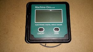
Here’s a useful tool for the kit, a digital angle gauge/protractor. These use a silicon sensor to show the number of degrees the unit is out of level.

Magnets!
Magnets!

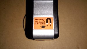
Magnets are provided in the base, so the tool can attach to any ferrous surface.

Battery Box
Battery Box

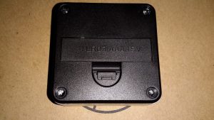
Power is provided by a single AAA cell.

Main PCB
Main PCB

Removing the rear cover reveals the brains of the unit, and there’s not much to it at all. The main microcontroller is a CoB-type device, so no part numbers available from that one.

Sensing Element
Sensing Element

The IC to the left of the main microcontroller is the sensing element. There’s no markings on this inclinometer IC so I’m not sure of the specs, but it will be a 3D-MEMS device of some sort.

Power Supply
Power Supply

The other side of the PCB has the power supply for the logic, and a serial EEPROM, probably storing calibration data.

Posted on Leave a comment

IC Decap: Motorola XPC860PZP50D4 Communications Controller

XPC860PZP50D4 Package

This is a System On Chip from Motorola, designed for network routing applications. This chip contains a hell of a feature set, so I’ll just include an excerpt from the datasheet:

XPC860PZP50D4 Die
XPC860PZP50D4 Die
Embedded single-issue, 32-bit MPC8xx core (implementing the PowerPC
architecture) with thirty-two 32-bit general-purpose registers (GPRs)
— The core performs branch prediction with conditional prefetch, without
conditional execution
— 4- or 8-Kbyte data cache and 4- or 16-Kbyte instruction cache (see Table 1)
– 16-Kbyte instruction caches are four-way, set-associative with 256 sets;
4-Kbyte instruction caches are two-way, set-associative with 128 sets.
– 8-Kbyte data caches are two-way, set-associative with 256 sets; 4-Kbyte data
caches are two-way, set-associative with 128 sets.
– Cache coherency for both instruction and data caches is maintained on 128-bit
(4-word) cache blocks.
– Caches are physically addressed, implement a least recently used (LRU)
replacement algorithm, and are lockable on a cache block basis.
— Instruction and data caches are two-way, set-associative, physically addressed,
LRU replacement, and lockable on-line granularity.
— MMUs with 32-entry TLB, fully associative instruction, and data TLBs
— MMUs support multiple page sizes of 4, 16, and 512 Kbytes, and 8 Mbytes; 16
virtual address spaces and 16 protection groups
— Advanced on-chip-emulation debug mode
Up to 32-bit data bus (dynamic bus sizing for 8, 16, and 32 bits)
32 address lines
Operates at up to 80 MHz
Memory controller (eight banks)
— Contains complete dynamic RAM (DRAM) controller
— Each bank can be a chip select or RAS to support a DRAM bank
— Up to 15 wait states programmable per memory bank
— Glueless interface to DRAM, SIMMS, SRAM, EPROM, Flash EPROM, and
other memory devices.
— DRAM controller programmable to support most size and speed memory
interfaces
— Four CAS lines, four WE lines, one OE line
— Boot chip-select available at reset (options for 8-, 16-, or 32-bit memory)
— Variable block sizes (32 Kbyte to 256 Mbyte)
— Selectable write protection
— On-chip bus arbitration logic
General-purpose timers
— Four 16-bit timers or two 32-bit timers
— Gate mode can enable/disable counting
— Interrupt can be masked on reference match and event capture
System integration unit (SIU)
— Bus monitor
— Software watchdog
— Periodic interrupt timer (PIT)
— Low-power stop mode
— Clock synthesizer
— Decrementer, time base, and real-time clock (RTC) from the PowerPC
architecture
— Reset controller
— IEEE 1149.1 test access port (JTAG)
Interrupts
— Seven external interrupt request (IRQ) lines
— 12 port pins with interrupt capability
— 23 internal interrupt sources
— Programmable priority between SCCs
— Programmable highest priority request
10/100 Mbps Ethernet support, fully compliant with the IEEE 802.3u Standard (not
available when using ATM over UTOPIA interface)
ATM support compliant with ATM forum UNI 4.0 specification
— Cell processing up to 50–70 Mbps at 50-MHz system clock
— Cell multiplexing/demultiplexing
— Support of AAL5 and AAL0 protocols on a per-VC basis. AAL0 support enables
OAM and software implementation of other protocols).
— ATM pace control (APC) scheduler, providing direct support for constant bit rate
(CBR) and unspecified bit rate (UBR) and providing control mechanisms
enabling software support of available bit rate (ABR)
— Physical interface support for UTOPIA (10/100-Mbps is not supported with this
interface) and byte-aligned serial (for example, T1/E1/ADSL)
— UTOPIA-mode ATM supports level-1 master with cell-level handshake,
multi-PHY (up to 4 physical layer devices), connection to 25-, 51-, or 155-Mbps
framers, and UTOPIA/system clock ratios of 1/2 or 1/3.
— Serial-mode ATM connection supports transmission convergence (TC) function
for T1/E1/ADSL lines; cell delineation; cell payload scrambling/descrambling;
automatic idle/unassigned cell insertion/stripping; header error control (HEC)
generation, checking, and statistics.
Communications processor module (CPM)
— RISC communications processor (CP)
— Communication-specific commands (for example, GRACEFUL STOP TRANSMIT ,
ENTER HUNT MODE , and RESTART TRANSMIT )
— Supports continuous mode transmission and reception on all serial channels
— Up to 8Kbytes of dual-port RAM
— 16 serial DMA (SDMA) channels
— Three parallel I/O registers with open-drain capability
Four baud-rate generators (BRGs)
— Independent (can be connected to any SCC or SMC)
— Allow changes during operation
— Autobaud support option
Four serial communications controllers (SCCs)
— Ethernet/IEEE 802.3 optional on SCC1–4, supporting full 10-Mbps operation
(available only on specially programmed devices).
— HDLC/SDLC (all channels supported at 2 Mbps)
— HDLC bus (implements an HDLC-based local area network (LAN))
— Asynchronous HDLC to support PPP (point-to-point protocol)
— AppleTalk
— Universal asynchronous receiver transmitter (UART)
— Synchronous UART
— Serial infrared (IrDA)
— Binary synchronous communication (BISYNC)
— Totally transparent (bit streams)
— Totally transparent (frame based with optional cyclic redundancy check (CRC))
Two SMCs (serial management channels)
— UART
— Transparent
— General circuit interface (GCI) controller
— Can be connected to the time-division multiplexed (TDM) channels
One SPI (serial peripheral interface)
— Supports master and slave modes
— Supports multimaster operation on the same bus
One I 2 C (inter-integrated circuit) port
— Supports master and slave modes
— Multiple-master environment support
Time-slot assigner (TSA)
— Allows SCCs and SMCs to run in multiplexed and/or non-multiplexed operation
— Supports T1, CEPT, PCM highway, ISDN basic rate, ISDN primary rate, user
defined
— 1- or 8-bit resolution
— Allows independent transmit and receive routing, frame synchronization,
clocking
— Allows dynamic changes
— Can be internally connected to six serial channels (four SCCs and two SMCs)
Parallel interface port (PIP)
— Centronics interface support
— Supports fast connection between compatible ports on the MPC860 or the
MC68360
PCMCIA interface
— Master (socket) interface, release 2.1 compliant
— Supports two independent PCMCIA sockets
— Eight memory or I/O windows supported
Low power support
— Full on—all units fully powered
— Doze—core functional units disabled, except time base decrementer, PLL,
memory controller, RTC, and CPM in low-power standby
— Sleep—all units disabled, except RTC and PIT, PLL active for fast wake up
— Deep sleep—all units disabled including PLL, except RTC and PIT
— Power down mode— all units powered down, except PLL, RTC, PIT, time base,
and decrementer
Debug interface
— Eight comparators: four operate on instruction address, two operate on data
address, and two operate on data
— Supports conditions: = ≠ < >
— Each watchpoint can generate a break-point internally
3.3 V operation with 5-V TTL compatibility except EXTAL and EXTCLK
357-pin ball grid array (BGA) package
Posted on Leave a comment

IC Decapping: The Process

As I’ve been posting some photos of decapped ICs lately, I thought I’d share the process I use personally for those that might want to give it a go 😉

The usual method for removing the epoxy package from the silicon is to use hot, concentrated Nitric Acid. Besides the obvious risks of having hot acids around, the decomposition products of the acid, namely NO² (Nitrogen Dioxide) & NO (Nitrogen Oxide), are toxic and corrosive. So until I can get the required fume hood together to make sure I’m not going to corrode the place away, I’ll leave this process to proper labs ;).

The method I use is heat based, using a Propane torch to destroy the epoxy package, without damaging the Silicon die too much.

TMS57002 Audio DSP
TMS57002 Audio DSP

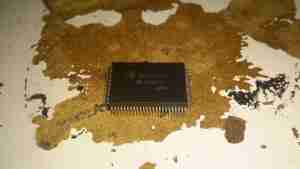
I start off, obviously, with a desoldered IC, the one above an old audio DSP from TI. I usually desolder en-masse for this with a heat gun, stripping the entire board in one go.

FLAMES!
FLAMES!

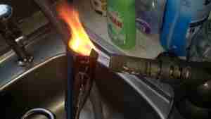
Next is to apply the torch to the IC. A bit of practice is required here to get the heat level & time exactly right, overheating will cause the die to oxidize & blacken or residual epoxy to stick to the surface.
I usually apply the torch until the package just about stops emitting it’s own yellow flames, meaning the epoxy is almost completely burned away. I also keep the torch flame away from the centre of the IC, where the die is located.
Breathing the fumes from this process isn’t recommended, no doubt besides the obvious soot, the burning plastic will be emitting many compounds not brilliant for Human health!
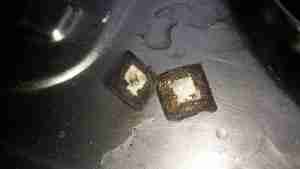
Once the IC is roasted to taste, it’s quenched in cold water for a few seconds. Sometimes this causes such a high thermal shock that the leadframe cracks off the epoxy around the die perfectly.

All Your Die Belong To Us

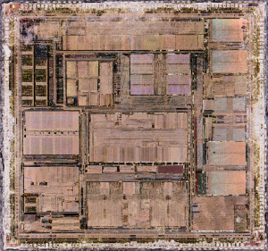
Now that the epoxy has been destroyed, it breaks apart easily, and is picked away until I uncover the die itself. (It’s the silver bit in the middle of the left half). The heat from the torch usually destroys the Silver epoxy holding the die to the leadframe, and can be removed easily from the remaining package.

Decapped
Decapped

BGA packages are usually the easiest to decap, flip-chip packages are a total pain due to the solder balls being on the front side of the die, I haven’t managed to get a good result here yet, I’ll probably need to chemically remove the first layer of the die to get at the interesting bits 😉

Slide
Slide

Once the die has been rinsed in clean water & inspected, it’s mounted on a glass microscope slide with a small spot of Cyanoacrylate glue to make handling easier.

Some dies require some cleaning after decapping, for this I use 99% Isopropanol & 99% Acetone, on the end of a cotton bud. Any residual epoxy flakes or oxide stuck to the die can be relatively easily removed with a fingernail – turns out fingernails are hard enough to remove the contamination, but not hard enough to damage the die features.

Once cleaning is complete, the slide is marked with the die identification, and the photographing can begin.

Microscope Mods

I had bought a cheap eBay USB microscope to get started, as I can’t currently afford a proper metallurgical microscope, but I found the resolution of 640×480 very poor. Some modification was required!

Modified Microscope
Modified Microscope

I’ve removed the original sensor board from the back of the optics assembly & attached a Raspberry Pi camera board. The ring that held the original sensor board has been cut down to a minimum, as the Pi camera PCB is slightly too big to fit inside.
The stock ring of LEDs is run direct from the 3.3v power rail on the camera, through a 4.7Ω resistor, for ~80mA. I also added a 1000µF capacitor across the 3.3v supply to compensate a bit for the long cable – when a frame is captured the power draw of the camera increases & causes a bit of voltage drop.

The stock lens was removed from the Pi camera module by careful use of a razor blade – being too rough here *WILL* damage the sensor die or the gold bond wires, which are very close to the edge of the lens housing, so be gentle!

Mounting Base
Mounting Base

The existing mount for the microscope is pretty poor, so I’ve used a couple of surplus ceramic ring magnets as a better base, this also gives me the option of raising or lowering the base by adding or removing magnets.
To get more length between the Pi & the camera, I bought a 1-meter cable extension kit from Pi-Cables over at eBay, cables this long *definitely* require shielding in my space, which is a pretty aggressive RF environment, or interference appears on the display. Not surprising considering the high data rates the cable carries.
The FFC interface is hot-glued to the back of the microscope mount for stability, for handheld use the FFC is pretty flexible & doesn’t apply any force to the scope.

Die Photography

Since I modified the scope with a Raspberry Pi camera module, everything is done through the Pi itself, and the raspistill command.

Pi LCD
Pi LCD

The command I’m currently using to capture the images is:
raspistill -ex auto -awb auto -mm matrix -br 62 -q 100 -vf -hf -f -t 0 -k -v -o CHIPNAME_%03d.jpg

This command waits between each frame for the ENTER key to be pressed, allowing me to position the scope between shots. Pi control & file transfer is done via SSH, while I use the 7″ touch LCD as a viewfinder.

The direct overhead illumination provided by the stock ring of LEDs isn’t ideal for some die shots, so I’m planning on fitting some off-centre LEDs to improve the resulting images.

Image Processing

Obviously I can’t get an ultra-high resolution image with a single shot, due to the focal length, so I have to take many shots (30-180 per die), and stitch them together into a single image.
For this I use Hugin, an open-source panorama photo stitching package.

Hugin
Hugin

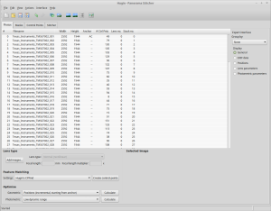
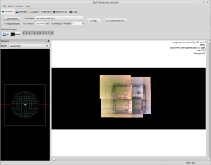
Here’s Hugin with the photos loaded in from the Raspberry Pi. To start with I use Hugin’s built in CPFind to process the images for control points. The trick with getting good control points is making sure the images have a high level of overlap, between 50-80%, this way the software doesn’t get confused & stick the images together incorrectly.

Optimiser
Optimiser

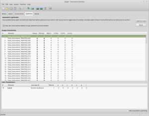
After the control points are generated, which for a large number of high resolution images can take some time, I run the optimiser with only Yaw & Pitch selected for all images.

Optimising
Optimising

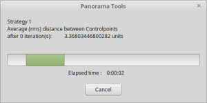
If all goes well, the resulting optimisation will get the distance between control points to less than 0.3 pixels.

Panorama Preview
Panorama Preview

After the control points & optimisation is done, the resulting image can be previewed before generation.

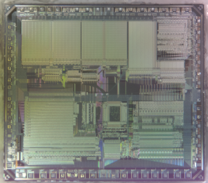
Texas Instruments TMS67002

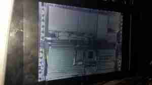
After all the image processing, the resulting die image should look something like the above, with no noticeable gaps.

Posted on Leave a comment

µRadMonitor RRDTool Graphing

I’ve been meaning to sort some local graphs out for a while for the radiation monitor, and I found a couple of scripts created by a couple of people over at the uRadMonitor forums for doing exactly this with RRDTool.

µRadLogger
µRadLogger

Using another Raspberry Pi I had lying around, I’ve implemented these scripts on a minimal Raspbian install, and with a couple of small modifications, the scripts upload the resulting graphs to the blog’s webserver via FTP every minute.

[snippet id=”1759″]

This script just grabs the current readings from the monitor, requiring access to it’s IP address for this.

[snippet id=”1760″]

This script sets up the RRDTool data files & directories.

[snippet id=”1761″]

The final script here does all the data collection from the monitor, updates the RRDTool data & runs the graph update. This runs from cron every minute.
I have added the command to automate FTP upload when it finishes with the graph generation.

This is going to be mounted next to the monitor itself, running from the same supply.

The Graphs are available over at this page.

Posted on Leave a comment

Opticon OPN-2001 Barcode Scanner

OPN-2001
OPN-2001

Random teardown time!

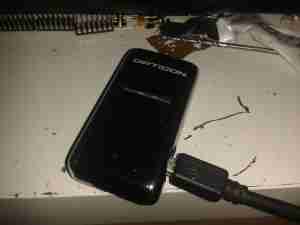
The OPN-2001 is a very small handheld barcode data collection device, used for stock keeping, inventory, etc.

It’s powered by an internal Li-Poly cell, at 150mAh, and has storage for 1000 barcodes in it’s internal memory.

USB
USB

The unit is charged via it’s USB port, the data can also be downloaded using this interface.

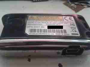
ID Label
ID Label

Here’s the bottom of the unit with it’s label. Serial number removed to protect the guilty. 😉

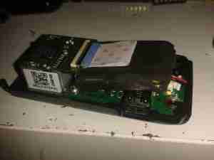
Cover Removed
Cover Removed

Here the bottom cover has been removed from the scanner, showing the internals. The barcode engine is on the left, this contains all the hardware & logic for scanning & storing the barcode data. The Li-Poly cell is under the FFC cable wrapped in foam tape for protection.

PCB Removed
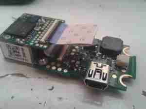
PCB Removed

Here’s the PCB & engine assembly removed from the casing. The lower PCB appears to just handle the user interface buttons, beeper & USB power & charging circuitry. All the processing logic is on the barcode engine itself.

PCB Reverse
PCB Reverse

Here’s the back of the support PCB, with the pair of buttons for scanning & deleting barcodes. Also on this board is a 32kHz clock crystal & a Ricoh RV5C386A RTC IC. This communicates with the main processor via I²C for storing the date & time with the barcodes. At the bottom right corner are some of the power supply passives.

Support PCB
Support PCB

Here’s the other side of the support PCB, with the beeper, battery connector & the switching regulator to provide the barcode engine with 3.3v power.

Barcode Engine
Barcode Engine

Here’s the barcode engine itself, which is absolutely tiny, at roughly 20mm square. The main processor & it’s associated Flash ROM are on this PCB. The main processor has an ARM7 32bit core, with 64kB of RAM, and onboard 512kB of ROM for program & barcode storage.

Mirror
Mirror

Here’s the business end of the barcode engine, the mirror vibrates at 100Hz to produce the scan line. The laser diode is rated at 1mW, 650nm. This is in the deep red range.


Posted on Leave a comment

QSO Logging Systems

As per my site update post, I have migrated my radio log onto a new system, from CQRLOG.

CQR log has served me well since I first started in Amateur Radio, however it’s a bit complex to use, requires a backend MySQL server for it’s database, and as it’s a local application, it’s not possible to share my log with other Hams without some difficulty.
The only other major system with an online logging system is QRZ, and I find that particular site a bit of a pain, and many of the features there aren’t free. (Although it’s not horrendously expensive, I’m on a very tight budget & I must save where I can).

CQRLOG
CQRLOG Screenshot

Because of these points, I went on a search for something that would better serve my needs. I have discovered during this search that there’s liitle out there in the self-hosted respect.

I did however find Cloudlog, a web based logging system in PHP & MySQL.
This new system allows integration with the main site, as I can run it on the same server & LAMP stack, it’s very simple to use, is visually pleasing and it even generates a Google Map view of recent QSO locations.
It will also allow me to save some resources on my main PC, running a full-blown MySQL server in the background just for a single application is resource intensive, and a bit of a waste of CPU cycles. (CQRLOG and it’s associated MySQL server is 300MB of disk space, CloudLog is 27MB).

Backups are made simpler with this system also, as it’s running on my core systems, incremental backups are taken every 3 hours, with a full system backup every 24 hours. Combined with offsite backup sync, data loss is very unlikely in any event. All this is completely automatic.
I can also take an ADIF file from Cloudlog for use with any other logging application, if the need arises.

Cloudlog is built & maintained by Peter Goodhall, 2E0SQL.
From the looks of Github, there’s also a version 2 in development, although now I have version 1 up & running, I might just stick with it, unless an easy upgrade path is available.

When I am not operating mobile, new QSOs should appear in this system almost immediately, with their respective pins on the map. (These are generated by the Grid Square location, so accuracy may vary).
If you’ve spoken to me on the air & I haven’t updated it, I’m most likely away from an internet connection, in which case your callsign will appear as soon as I have access.

73s for now folks!

Posted on 7 Comments

3″ CRT Composite Monitor

CRT Module

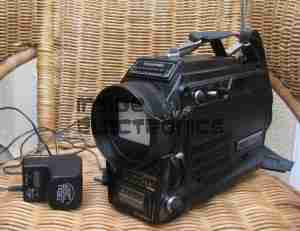
I recently managed to score a 3″ B&W portable TV on eBay, a Panasonic TR-3000G. As these old units are now useless, thanks to the switch off of analogue TV signalling, I figured I could find a composite signal internally & drive the CRT with an external source.

Panasonic TR-3000G
Panasonic TR-3000G

Here’s the TV in it’s native state. Running from 9v DC, or 6 D size cells. I’m guessing from somewhere around the 1970’s. Here is the CRT & associated drive circuitry, removed from the casing:

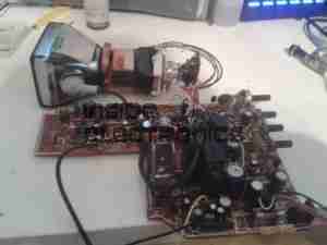
CRT Module
CRT Module

After dissecting the loom wiring between the CRT board & the RF/tuner board, I figured out I had to short out Pins 1,2 & 5 on the H header to get the CRT to operate straight from the power switch. This board also generates the required voltages & signals to drive the RF tuner section. I have removed the loom from this, as the PCB operates fine without. It doesn’t seem to be fussy about power input either: it’s specified at 9v, but seems to operate fine between 7.5v & 14.5v DC without issue.

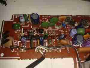
Video Connections
Video Connections

Tracing the wiring from the tuner PCB revealed a length of coax snaking off to the section marked Video/Sync. I successfully found the composite input!

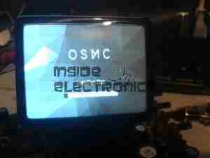
Running OSMC
Running OSMC

A quick bit of wiring to a Raspberry Pi, & we have stable video! For such an old unit, the picture quality is brilliant, very sharp focus.

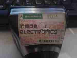
Matsushita 85VB4 CRT

Closeup of the CRT itself. I haven’t been able to find much data on this unit, but I’m guessing it’s similar to many commercial viewfinder CRTs.

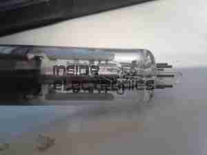
Electron Gun Closeup

Amazingly, there isn’t a single IC in the video circuitry, it’s all discrete components. This probably accounts for the large overall size of the control PCB. Viewfinder CRTs from a few years later on are usually driven with a single IC & a few passives that provide all the same functions.  

Posted on Leave a comment

Lying Again Are We? (Mike Webb Of Hydraulicgenerators.co.uk)

Regular readers might remember a previous post about the fiasco we have had with a hydraulic generator, and in particular one person by the name of Mike Webb.

Well here we are a year down the line. The generator still doesn’t function properly, as other things have taken priority, but this is being remedied this week with a replacement hydraulic powerhead. (Correctly sized to 6cc this time, not 11cc).

I even finally got a response from Mike, most likely due to my previous post & the negative publicity that would have brought. In July Mike wrote this:

Good Morning Ben,


I have read your article on the above website, not entirely sure what I can say.


I do however sincerely apologise for the way I handled things, I could give numerous reasons, but I guess they are not your concern, I behaved badly and I am disappointed in myself for treating anyone in this way.


The business has now folded, the domain name www.hydraulicgenerators.co.uk and related products are now owned, manufactured and sold by another company.


My only hope now is that I can in some way repair the damage that has been done and hope that somewhere within yourself you can find a way to accept my apology and forgive me, I am genuinely not a bad person but circumstances outside of my control at the time led me to act in an inacceptable way.


I can understand how you feel, I was defrauded out of a considerable amount of money a while ago and seeking revenge has not been far from my mind for a considerable time, but it won’t get my money back, it won’t undo the damage that has already been done and whilst I might feel better about it for a short while, I have found it difficult from a personal perspective, as, whilst you may cast aspersions about me, my conscience and I do have one just won’t allow me, I can’t help myself from thinking of the other people that would be impacted upon that are otherwise innocent and I know in this particular instance there are several.


I can only hope that you accept my most sincere apology.

Right then. Where should I begin.

No Mike, I will never EVER forgive someone for, what was in my eyes, a deliberate act of fraud & a complete refusal to co-operate.

Now, being the resourceful person I am, and my ability (like anyone else with brains), to find out the registrar of domain names, have discovered the man is yet again lying. Company folded? I think not my son.

Two other domain names have popped up with Mike’s name on the Registrar details:
ukgenerators.co.uk
shop4generators.co.uk

(For completeness, here are the full registrar details, just in case things change after I publish this. This information is correct as of 9/12/14)

Domain name:
        ukgenerators.co.uk

    Registrant:
        Mike Webb

    Registrant type:
        UK Individual

    Registrant’s address:
 <REDACTED>

    Data validation:
        Registrant contact details validated by Nominet on 10-Dec-2012

    Registrar:
        LCN.com Ltd [Tag = LCN]
        URL: http://www.lcn.com

    Relevant dates:
        Registered on: 06-Feb-2004
        Expiry date:  06-Feb-2016
        Last updated:  16-Jan-2014

    Registration status:
        Registered until expiry date.

    Name servers:
        ns1.hostpapa.com
        ns2.hostpapa.com

    WHOIS lookup made at 16:56:14 09-Dec-2014

    Domain name:
        shop4generators.co.uk

    Registrant:
        Mike Webb

    Registrant type:
        UK Individual

    Registrant’s address:
        The registrant is a non-trading individual who has opted to have their
        address omitted from the WHOIS service.

    Data validation:
        Registrant contact details validated by Nominet on 10-Dec-2012

    Registrar:
        Webfusion Ltd t/a 123-reg [Tag = 123-REG]
        URL: http://www.123-reg.co.uk

    Relevant dates:
        Registered on: 02-Jun-2005
        Expiry date:  02-Jun-2015
        Last updated:  27-Jun-2013

    Registration status:
        Registered until expiry date.

    Name servers:
        ns1.hostpapa.com
        ns2.hostpapa.com

    WHOIS lookup made at 16:55:43 09-Dec-2014


Now for someone who is obviously attempting to tell me that he has no money or resources to reimburse us for the utter hell we have been put through in this situation, seems to be doing pretty well for themselves, in the same business that has apparently ‘folded’.
You have a shiny new logo & business name, and yet apparently have ceased trading?
Now, having been part of a firm during a takeover/company sale, domain names are usually immediately transferred into the name of the buying company. Not in this case it seems. All domains are still registered to you.
Your LinkedIn account still has you as being in the business, along with your Twitter account & YouTube account.
Not to mention, that one one of the aforementioned sites (the original hydraulicgenerators.co.uk), Mike’s E-Mail address is still very much visible on the front page E-Mail Link!

Despite all this evidence of continued trading, according to Companies House, the company is in fact in liquidation: http://data.companieshouse.gov.uk/doc/company/06770818

If this is the case, then Mike Webb is in fact operating illegally.

Mike, if you do read this, I AM NOT AN IDIOT. All I asked was that you put things right, so we would have a WORKING GENERATOR.
So far all this has cost is time & money, and I certainly don’t like being conned.
However I feel it is my duty to make sure that anyone who ever has the misfortune of dealing with you knows exactly what you have previous form for doing.

Legal notice:
All information contained in this post is correct as of 9/12/14. Information will be kept up to date & factually correct to the best of my ability.

Stay tuned for the final chapter in getting this generator fitted & working.
Posted on Leave a comment

Quantum LTO2 CL1001 Tape Drive Teardown

Drive Top
Drive Top

I have recently begun to create an archive of all my personal data, and since LTO2 tape drives offer significant capacity (200GB/400GB) per tape, longevity is very high (up to 30 years in archive), & relatively low cost, this is the technology I’ve chosen to use for my long term archiving needs.

Unfortunately, this drive was DOA, due to being dropped in shipping. This drop broke the SCSI LVD connector on the back of the unit, & bent the frame, as can be seen below.

Broken SCSI
Broken SCSI

As this drive is unusable, it made for a good teardown candidate.

Cover Removed
Cover Removed

Here the top cover of the drive has been removed, showing the top of the main logic PCB. The large silver IC in the top corner is the main CPU for the drive. It’s a custom part, but it does have an ARM core.

The two Hitachi ICs are the R/W head interface chipset, while the smaller LSI IC is the SCSI controller.
The tape transport & loading mech can be seen in the lower half of the picture.

Main Logic
Main Logic

Close up of the main logic.

Tape Spool
Tape Spool

Here the main logic PCB has been removed, showing the tape take up spool. The data cartridges have only one spool to make the size smaller. When the tape is loaded, the drive grabs onto the leader pin at the end of the tape & feeds it onto this spool.
The head assembly is just above the spool.

Bottom Plate Removed

Bottom of the drive with the cover plate removed. Here the spindle drive motors are visible, both brushless 3-Phase units. Both of these motors are driven by a single controller IC on the other side of the lower logic PCB.

Head Drive Motor
Head Drive Motor

The head is moved up & down the face of the tape by this stepper motor for coarse control, while fine control is provided by a voice coil assembly buried inside the head mount.

Tape Head Assembly
Tape Head Assembly

The face of the tape R/W head. This unit contains 2 sets of 8 heads, one of which writes to the tape, the other then reads the written data back right after to verify integrity.

Cartridge Load Motor

The tape cartridge loading motor. I originally thought that this was a standard brushed motor, but it has a ribbon cable emerging, this must be some sort of brushless arrangement.

A replacement drive is on the way, I shall be documenting some more of my archiving efforts & system setup once that unit arrives.

Posted on Leave a comment

Raspberry Pi Geiger Counter

Geiger Counter Setup

Here’s my latest project with the Pi: interfacing it with the Sparkfun Geiger counter & outputting the resulting data to a character LCD.

The geiger counter is interfaced with it’s USB port, with the random number generator firmware. A Python script reads from the serial port & every minute outputs CPM & µSv/h data to the display.

The Python code is a mash of a few different projects I found online, for different geiger counters & some of my own customisations & code to write the info to the display & convert CPM into µSv/h.

This also writes all the data into a file at /var/log/radlog.txt

The code for this is below:

[snippet id=”1149″]

Info Display
Info Display
Posted on Leave a comment

Wearable Raspberry Pi – Some Adjustments

USB Hub
USB Hub

As the first USB hub I was using was certainly not stable – it would not enumerate between boots & to get it working again would require waiting around 12 hours before applying power, it has been replaced. This is a cheapie eBay USB hub, of the type shown below.

These hubs are fantastic for hobbyists, as the connections for power & data are broken out on the internal PCB into a very convenient row of pads, perfect for integration into many projects.

Breakout Hub
Breakout Hub

I now have two internal spare USB ports, for the inbuilt keyboard/mouse receiver & the GPS receiver I plan to integrate into the build.

These hubs are also made in 7-port versions, however I am not sure if these have the same kind of breakout board internally. As they have the same cable layout, I would assume so.


Connector Panel
Connector Panel

Here is a closeup of the back of the connectors, showing a couple of additions.

I have added a pair of 470µF capacitors across the power rails, to further smooth out the ripple in the switching power supply, as I was having noise issues on the display.

Also, there is a new reset button added between the main interface connectors, which will be wired into the pair of pads that the Raspberry Pi has to reset the CPU.
This can be used as a power switch in the event the Pi is powered down when not in use & also to reset the unit if it becomes unresponsive.


Posted on Leave a comment

New Feature – Geiger Counter

Here’s something new, an internet connected Geiger counter! The graph in the sidebar is updated once every 60 seconds, and can be clicked on for a larger version. Measurements are in Counts Per Minute, the graph logs 1 hour of data.


The counter itself is a Sparkfun Geiger counter, with the end cap removed from the tube so it can also detect alpha radiation.

Connected through USB, a Perl script queries the emulated serial port for the random 1 or 0 outputted by the counter when it detects a particle. The graph is pretty basic, but it gets the point across. Anybody who wishes to contribute to improve the graphing is welcome to comment!

Geiger Counter
Geiger Counter
Posted on Leave a comment

Nokia 7110

Front
Front

Another phone from the mid 90s. This is the nokia 7110.

Slider Open
Slider Open

Here the slider is open showing the keypad.

Battery Removed
Battery Removed

Here the battery is removed, a Li-Ion unit.

Battery
Battery

The battery cell & protection circuit removed from the casing.

Rear Of PCB
Rear Of PCB

This is the rear of the PCB removed from the housing. Data & charging ports on the right hand side f the board.
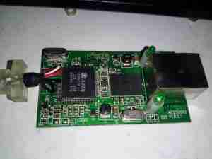
Front Of PCB
Front Of PCB

Front of the PCB with the RF sections at the left hand side & the keypad contacts on the right.

RF Sections
RF Sections

Closeup of the RF sections of the board, big silver rectangular cans are VCO units.

SIM Connector
SIM Connector

Closeup of the top rear section of the PCB, with SIM cnnector, battery contacts, IR tranciever at the far left. Bottom centre is the external antenna connector.

CPU
CPU

The logic section of the board, Large chip is CPU, to right of that is the ROM storing the machine code. Other chips are unknown custom parts.

Mic & Speaker
Mic & Speaker

The Mic & the loudspeaker removed from it’s housing.
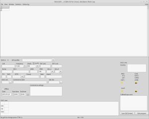
LCD
LCD

LCD from the front of the unit, SPI interfaced. Flex PCB also contains the power button, loudspeaker contacts & a temperature sensor.

Scroll Wheel
Scroll Wheel

The scroll wheel removed from the front housing.
Vibra-Motor
Vibra-Motor

Tiny vibration motor removed from the rear housing, alerts the user to a text or phone call.