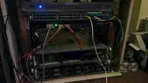
There have been quite a few updates to the hosting solution for this site, which is hosted locally in my house, from the above setup, in a small comms rack, to a new 22U half rack, with some hardware upgrades to come.
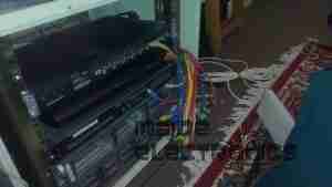
Core switch here has been removed, with the rest of the core network equipment. The site was kept online by a direct connection into the gateway to the intertubes.
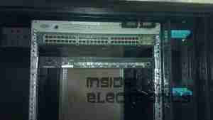
New 22U rack, with the core switch, FC switch & management & monitoring server installed.
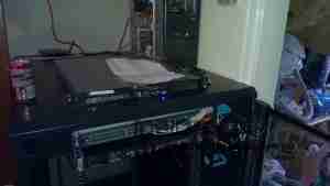
As I had no rack rails to start with, the servers were placed on the top of the rack to start off, here is the Dell PowerEdge 860 pfSense core router installed, with the initial switch wiring to get the internal core network back online. This machine load balances two connections for an aggregated bandwidth of 140MB/s downstream & 15MB/s upstream.
The tower server behind is the NAS unit that runs the backups of the main & auxiliary webservers.
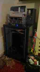
Still with no rack kits, all the servers are placed on top of the rack, before final installation. This allows running of the network before the rest of the equipment was installed.
The main server & aux server are HP ProLiant DL380 G3 servers, with redundant network connections.
Still to arrive are the final rack kits for the servers & a set of HP BL20p Blade servers, which will be running the sites in the future.
Stay tuned for more updates as they happen!
