Posted on 3 Comments

Wheelchair Motor Service Part 1: Teardown & Inspection

Trolley Propulsion System: Wheelchair Motor Units

So it’s time to get the propulsion system underway for the trolley, a pair of wheelchair motors were sourced for this, from HacMan. Since I don’t know how many hours are on these units, or how they’ve been treated in the past, I’m going to do a full service on them to ensure reliability. I decided on wheelchair motors due to their extreme ruggedness & heavily built components – this project when complete is going to weigh in at about 150kg!
I suspected something was amiss with one of the motors from running them under no load: the left hand wheelchair motor was heating up to the point of being too hot to touch, so this one at the very least needed some investigation.

Motor Disassembly & Assessment
Rear Cover Removed
Rear Cover Removed

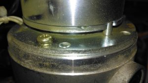
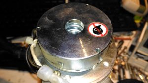
With the back cover removed from the motor the electromagnetic brake is revealed. This engages when power is removed to stop the motor freewheeling, which even though it’s a wormdrive box, it will do readily if backdriven.
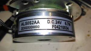
Electromagnetic Brake Assembly

The brake is rated 6.7W at 24v DC.

Brake Disc
Brake Disc

The brake disc is just visible between the plates of the brake here, with some green dust worn off the disc. When power is applied, the top disc, just under the magnet on top, is pulled upward against spring pressure away from the brake disc, which is attached to the motor armature.
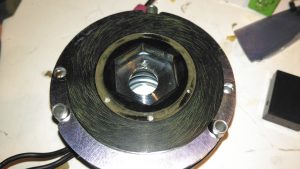
Brake Disc
Brake Disc

Here’s the brake disc, removed from the motor. There’s only a little wear here, as I’d expect – these brakes don’t engage until the motors have come to a complete stop.
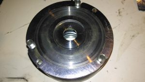
Brake Actuator
Brake Actuator

The steel disc above the magnet acts as one of the friction surfaces of the brake.
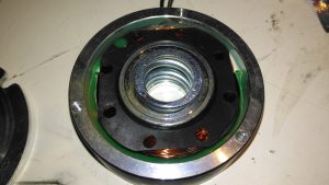
Brake Solenoid
Brake Solenoid

Finally, the solenoid is at the back, partially potted in resin. The strong coil spring in the centre applies the brakes when power is disconnected.
Gearbox Grok
Gearbox Grok

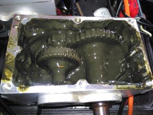
Removing the top of the gearbox reveals the state of the internals – There’s no wear at all on the gearset, but the lubricant is totally manky. The external oil seals have been leaking for some time, letting water in and grease out. The emulsified result is revolting! These gearboxes have a wormdrive first stage, the worm gear is underneath the left hand gearset. Steel spur gears then do the final gearing to the output shaft. The output gear is splined onto the output, and can slide along the shaft out of mesh – this is the freewheel clutch mechanism. At the moment it’s all obscured by the disgusting lubricant.
Input Shaft Seal
Input Shaft Seal

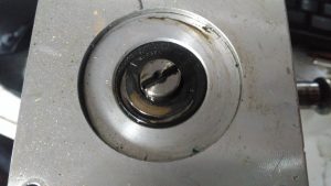
Here’s the failed seal on the left hand gearbox, the face damage was done by petrol immersion to clean everything up. (The seal is already compromised, so I’m not fussed about solvents eating the remaining rubber). The motor shaft is joined to the gearbox input by a rubber coupling.
Output Shaft Seal
Output Shaft Seal

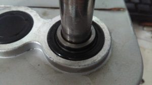
The output shaft seals seem to be still OK, there has been some seepage past the collar that the shaft rides in, but nothing more. This can be resealed with some Loctite bearing sealant. The sleeve is held into the gearbox by the wheel hub when in operation, but this doesn’t seal the gap unfortunately. I don’t know why the manufacturer didn’t just machine the shaft to that larger diameter, instead of using an extra sleeve to accommodate the seal.
Bore Seals
Bore Seals

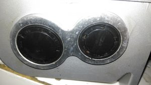
The bore seals covering the ends of the shafts are also fine, which is a good thing, since I can’t seem to find replacements for these anywhere. The input shaft seals will be replaced on both gearboxes though.
Motor Contamination
Motor Contamination

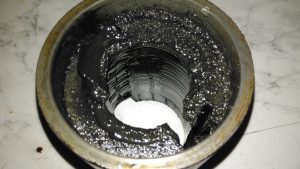
The oil seal must have been leaking for a long while! This is the gearbox end of the wheelchair motor frame, completely clogged with grease. Luckily only a small amount has made it down past the armature to the brushgear.
Damaged Commutator
Damaged Commutator

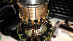
The commutator of this motor is badly damaged, and the brushes are very worn. This has been caused by the gearbox oil seal failing, and contaminating the motor internals with lubricant. The undercut between the segments is all but gone – filled with an abrasive mixture of brush dust, copper dust & old lubricant. Some repair work will be required here.
Second Motor
Second Motor

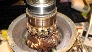
Here’s the brushgear removed from the second wheelchair motor, this one looks much more normal, and there’s not as much wear on the brushes or the commutator. Just the usual coating of brush dust.
Armatures
Armatures

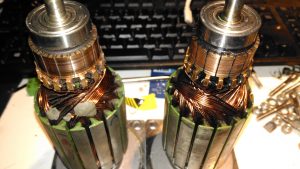
Here’s both armatures together, with the contaminated one on the right, after some cleaning to remove most of the greasy old grok & brush dust from everything. The windings on the damaged left hand wheelchair motor haven’t darkened, which I would expect from severe overheating damage, so I’m hoping this armature is OK, and won’t require a rewind. Using an ohmmeter on these windings doesn’t tell me much – there’s only 7 turns of 0.86mm (20AWG) magnet wire in each coil, so they read as a dead short anyway. There was some leakage between the windings and the core before I cleaned things up – this was in the high (28+) megohms range, but this seems to have cleared now I’ve given things a real good cleaning.

More to come when new bearings & seals arrive!
Posted on 10 Comments

Sony PS3 APS-231 Power Supply Voltage Mod

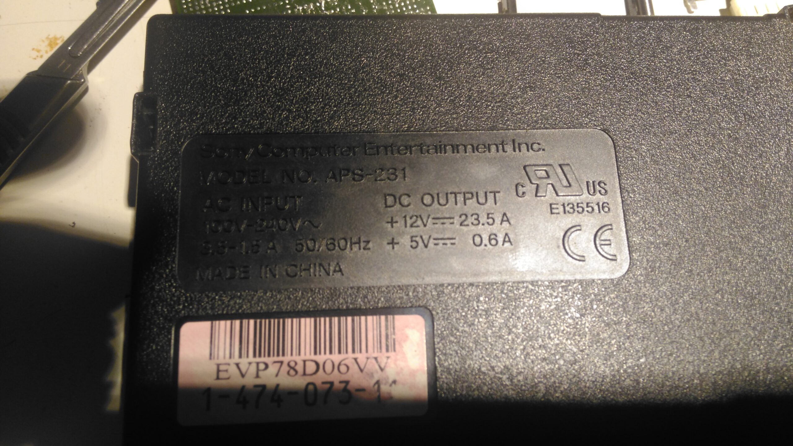
PSU Ratings
PSU Ratings
PSU Ratings

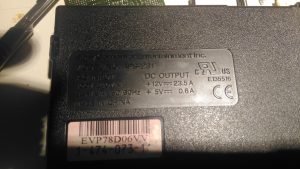
I was recently given a Sony PS3 with a dead disc drive, and since I’m not a console gamer I figured I’d see if there were any handy parts inside. Turns out these units contain a rather nice SMPS, the Sony APS-231 with a high power 12v rail, rated at 23.5A. A bit of searching around discovered a thread on the BadCaps Forums about voltage modding these supplies for a 13.8v output, suitable for my Ham radio gear.
These supplies are controlled by a Sony CXA8038A, for which there is very little information. Active PFC is included, along with synchronous rectification which increases the efficiency of the supply, and in turn, reduces the waste heat output from the rectifiers.

Regulation Section
Regulation Section

Like many of the SMPS units I’ve seen, the output voltage is controlled by referencing it to an adjustable shunt reference, and adjusting the set point of this reference will in turn adjust the output voltage of the supply, this is done in circuit by a single resistor.

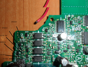
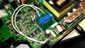
Here’s the regulator section of the PSU, with the resistors labelled. The one we’re after changing is the 800Ω one between pins 2 & 3 of the TS2431 shunt reference. It’s a very small 0402 size resistor, located right next to the filter electrolytic for the 5v standby supply circuit. A fine tip on the soldering iron is required to get this resistor removed.

Attachment Points
Attachment Points

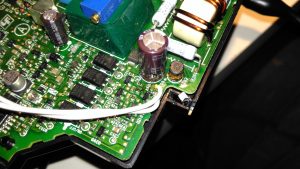
Once this resistor is removed from the circuit, a 1KΩ 18-turn potentiometer is fitted in it’s place, from the Anode (Pin 3) to the Ref. (Pin 2) pins of the TS2431 shunt reference. I initally set the potentiometer to be the same 800Ω as the factory set resistor, to make sure the supply would start up at a sensible voltage before I did the adjustment.

Potentiometer
Potentiometer

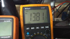
The pot is secured to the top of the standby supply transformer with a drop of CA glue to stop everything moving around. The supply can now be adjusted to a higher setpoint voltage – 13.8v is about the maxumum, as the OVP cuts the supply out at between 13.9v-14v.

Modded Voltage
Modded Voltage

After doing some testing at roughly 50% of the supply’s rated load, everything seems to be stable, and nothing is heating up more than I’d expect.

Posted on Leave a comment

nb Tanya Louise Heating Upgrades – Saloon Heating

With the installation of the new diesel fired heater we’ve noticed a small problem – since the only heat source in the saloon is the stove, even with the diesel heater fired up the temperature doesn’t really change much, as the heat from the radiators in the both the cabins & the head isn’t spreading far enough.

The solution to this problem is obviously an extra radiator in the saloon, however there isn’t the space to fit even a small domestic-style radiator. eBay turned up some heater matrix units designed for kit cars & the like:

3.8kW Matrix
3.8kW Matrix

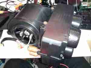
These small heater matrix units are nice & compact, so will fit into the back of a storage cupboard next to the saloon. Rated at a max heat output of 3.8kW, just shy of the stove’s rated 4kW output power, this should provide plenty of heating when we’re running the diesel heater rather than the fire.

Water & Power
Water & Power

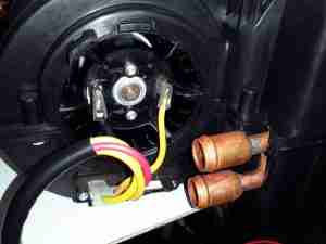
The blower motor has a resistor network to provide 3 speeds, but this probably won’t be used in this install, water connections are via 15mm copper tails. The current plan is to use a pipe thermostat on the flow from the boiler to switch on the blower when the water temperature reaches about 40°C.

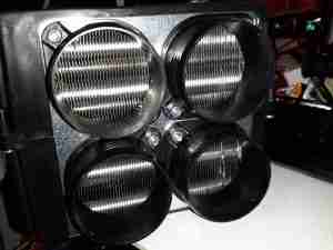
Hot Air Outlets
Hot Air Outlets

The hot air emerges from the matrix via 4 55mm duct sockets. This gives enough outlets to cover both the saloon & the corridor down to the cabins.

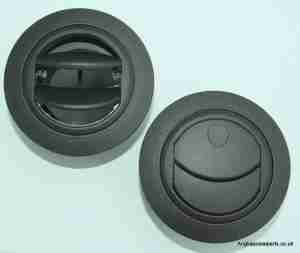
Hot Air Vents
Hot Air Vents

Standard 60mm Eberspacher style vents will be used to point the warmth where it’s needed.

More to come soon with the install!
Posted on 2 Comments

nb Tanya Louise Heating Upgrades – The Pumps


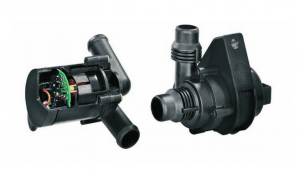
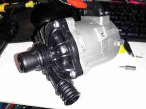
Pierburg WUP1
Pierburg WUP1

With some recent upgrades to the boat’s heating system, the hot water circulation pumps we’ve been using are becoming far too small for the job. After the original Johnson Marine circulation pump died of old age (the brushes wore down so far the springs ate the commutator) some time ago, it was replaced with a Pierburg WUP1 circulation pump from a BMW. (As we’re moored next to a BMW garage, these are easily obtainable & much cheaper than the marine pumps).

WUP1 Cutaway
WUP1 Cutaway

These are also brushless, where as the standard Johnson ones are brushed PM motors – the result here is a much longer working life, due to fewer moving parts.

The rated flow & pressure on these pumps is pretty pathetic, at 13L/min at 0.1bar head pressure. As the boat’s heating system is plumbed in 15mm pipe instead of 22mm this low pressure doesn’t translate to a decent flow rate. Turns out it’s pretty difficult to shove lots of water through ~110ft of 15mm pipe ;). Oddly enough, the very low flow rate of the system was never a problem for the “high output” back boiler on the stove – I suspect the “high output” specification is a bit optimistic.
This issue was recently made worse with the addition of a Webasto Thermo Top C 5kW diesel-fired water heater, which does have it’s own circulation pump but the system flow rate was still far too low to allow the heater to operate properly. The result was a rapidly cycling heater as it couldn’t dump the generated hot water into the rest of the system fast enough.

The easiest solution to the problem here is a larger pump with a higher head pressure capability. (The more difficult route would be completely re-piping the system in 22mm to lower the flow resistance). Luckily Pierburg produce a few pumps in the range that would fit the job.

Pierburg CWA-50
Pierburg CWA-50

Here’s the next size up from the original WUP1 pump, the CWA50. These are rated at a much more sensible 25L/min at 0.6bar head pressure. It’s physically a bit larger, but the connector sizes are the same, which makes the install onto the existing hoses easier. (For those that are interested, the hose connectors used on BMW vehicles for the cooling system components are NormaQuick PS3 type. These snap into place with an O-Ring & are retained by a spring clip).
The CWA50 draws considerably more power than the WUP1 (4.5A vs 1.5A), and are controllable with a PWM signal on the connector, but I haven’t used this feature. The PWM pin is simply tied to the positive supply to keep the pump running at maximum speed.

Once this pump was installed the head pressure immediately increased on the gauge from the 1 bar static pressure to 1.5 bar, indicating the pump is running at about it’s highest efficiency point. The higher water flow has so far kept the Webasto happy, there will be more to come with further improvements!

CWA-50 Pump Teardown

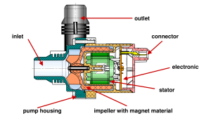
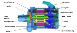
CWA50 Cutaway
CWA50 Cutaway

Above is a cutaway drawing of the new pump. These have a drilling through the shaft allows water to pass from the high pressure outlet fitting, through the internals of the pump & returns through the shaft to the inlet. This keeps the bearings cool & lubricated. The control & power drive circuitry for the 3-phase brushless motor is attached to the back & uses the water flowing through the rotor chamber as a heatsink. Overall these are very well made pumps.

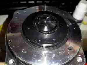
Impeller
Impeller

Here’s the impeller of the pump, which is very small considering the amount of power this unit has. The return port for the lubricating water can be seen in the centre of the impeller face.

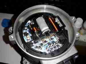
3-Phase Driver
3-Phase Driver

Inside the back of the pump is the control module. The main microcontroller is hiding under the plastic frame which holds the large power chokes & the main filter electrolytic.

Power Requirements for He-Ne Lasers

Power for a He-Ne laser is provided by a special high voltage power supply and consists of two parts (these maximum values depend on tube size – a typical 1 to 10 mW tube is assumed):

  • Operating voltage of 1,000 to 3,000v DC at 3 to 8mA.Like most low current discharge tubes, the He-Ne laser is a negative resistance device. As the current *increases* through the tube, the voltage across the tube *decreases*. The incremental magnitude of the negative resistance also increases with decreasing current.
  • Starting voltage of 5 to 12 kV at almost no current.In the case of a He-Ne tube, the initial breakdown voltage is much greater than the sustaining voltage. The starting voltage may be provided by a separate circuit or be part of the main supply.Often, you may find a wire or conductive strip running from the anode or ballast resistor down to a loop around the tube in the vicinity of the cathode. (Or there may be a recommendation for this in a tube spec sheet.) This external wire loop is supposed to aid in starting (probably where a pulse type starter is involved). There may even be some statistical evidence suggesting a reduction in starting times. I wouldn’t expect there to be much, if any, benefit when using a modern power supply but it might help in marginal cases. But, running the high voltage along the body of the tube requires additional insulation and provides more opportunity for bad things to happen (like short circuits) and may represent an additional electric shock hazard. And, since the strip has some capacitance, operating stability may be impaired. I would probably just leave well enough alone if a starting strip is present and the laser operates without problems but wouldn’t install one when constructing a laser head from components.

    With every laser I’ve seen using one of these strips, it has either had virtually or totally no effect on starting OR has caused problems with leakage to the grounded cylinder after awhile. Cutting away the strip in the vicinity of the anode has cured erratic starting problems in the latter case and never resulted in a detectable increase in starting time.

  • With a constant voltage power supply, a series ballast resistor is essential to limit tube current to the proper value. A ballast resistor will still be required with a constant current or current limited supply to stabilize operation. The ballast resistor may be included as part of a laser head but will be external for most bare tubes. (The exceptions are larger Spectra-Physics He-Ne lasers where the ballast resistors are also inside a glass tube extension, electrically connected but sealed off from the main tube.In order for the discharge to be stable, the total of the effective power supply resistance, ballast resistance, and tube (negative) resistance must be greater than 0 ohms at the operating point. If this is not the case, the result will be a relaxation oscillator – a flashing or cycling laser!
  • Power supply polarity is important for He-Ne tubes. Electrical behaviour may be quite different if powered with incorrect polarity and tube damage (and very short life) will likely be the result from prolonged operation.
    • The positive output of the power supply is connected to a series ballast resistor and then to the anode (small) electrode of the He-Ne tube. This electrode may actually be part of the mirror assembly at that end of the tube or totally separate from it. The distance from the resistors to the electrode should be minimized – no more than 2 or 3 inches.
    • The negative output of the power supply is connected to the cathode (large can) electrode of the He-Ne tube. This electrode may be electrically connected to the mirror mount at that end of the tube but is a separate aluminium cylinder that extends for several inches down the tube. CAUTION: Some He-Ne tubes use a separate terminal for the cathode and sometimes the anode as well, not the mirror mount(s). Powering one of these via the mirror mounts may result in lasing but will also result in tube damage.

    Note: He-Ne tube starting voltage is lower and operating voltage is higher when powered with reverse polarity. With some power supply designs, the tube may appear to work equally well or even better (since starting the discharge is easier) when hooked up incorrectly. However, this is damaging to the anode electrode of the tube (and may result in more stress on the power supply as well due to the higher operating voltage) and must be avoided (except possibly for a very short duration during testing).

  • Every He-Ne tube will have a nominal current rating. In addition to excessive heating and damage to the electrodes, current beyond this value does not increase laser beam intensity. In fact, optical output actually decreases (probably because too high a percentage of the helium/neon atoms are in the excited state). You can easily and safely demonstrate this behaviour if your power supply has a current adjustment or you run an unregulated supply using a Variac. While the brightness of the discharge inside the tube will increase with increasing current, the actual intensity of the laser beam will max out and then eventually decrease with increasing current. (This is also an easy way of determining optimal tube current if you have not data on the tube – adjust the ballast resistor or power supply for maximum optical output and set it so that the current is at the lower end of the range over which the beam intensity is approximately constant.) Optical noise in the output will also increase with excessive current.
  • The efficiency of the typical He-Ne laser is pretty pathetic. For example, a 2 mW HeNe tube powered by 1,400 V at 6mA has an efficiency of less than 0.025%. More than 99.975% of the power is wasted in the form of heat and incoherent light (from the discharge)! This doesn’t even include the losses of the power supply and ballast resistor.

A few He-Ne lasers – usually larger or research types – have used a radio frequency (RF) generator – essentially a radio transmitter to excite the discharge. This was the case with the original He-Ne laser but is quite rare today given the design of internal mirror He-Ne tubes and the relative simplicity of the required DC power supply.

Posted on Leave a comment

Mini USB Soldering Iron

USB Soldering Iron
USB Soldering Iron

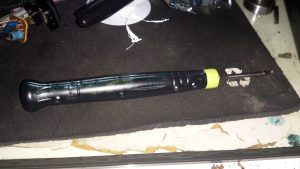
Here’s a novel little gadget, a USB powered soldering iron. The heating tip on these is very small & might be useful for very small SMD work. Bigger joints not so much, as it’s only rated at 8W. (Still breaks the USB standard of 2.5W from a single port).

These irons aren’t actually too bad to use, as long as the limitations in power are respected. Since nearly everything has a USB power port these days, it could make for a handy emergency soldering iron.

Heater Socket
Heater Socket

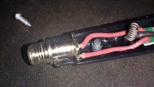
The heater & soldering bit are a single unit, not designed to be replaced separately. (I’ve not managed to find replacement elements, but at £3 for the entire iron, it would be pretty pointless).
Above is the socket where the heater plugs in, safely isolating the plastic body from any stray heat.

DC Input Jack
DC Input Jack

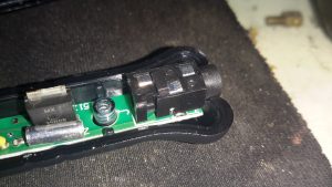
The DC input is a 3.5mm audio jack, a non-standard USB to 3.5mm jack cable is supplied. Such non-standard cables have the potential to damage equipment that isn’t expecting to see 5v on an audio input if it’s used incorrectly.

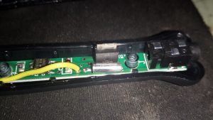
Touch Sensor & LED
Touch Sensor & LED

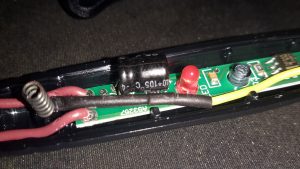
There isn’t actually a switch on this unit for power management, but a clever arrangement of a touch button & vibration switch. The vertical spring in the photo above makes contact with a steel ball bearing pressed into the plastic housing, forming the touch contact.

MOSFET
MOSFET

The large MOSFET here is switching the main heater current, the silver cylinder in front is the vibration switch, connected in parallel with the touch button.

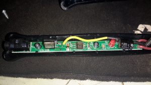
PCB
PCB

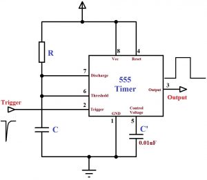
The main controller is very simple. It’s a 555 timer configured in monostable mode. Below is a schematic showing the basic circuit.

555 Monostable
555 Monostable

Big Clive also did a teardown & review of this iron. Head over to YouTube to watch.

Posted on 4 Comments

Eberspacher Controller & Remote

7-Day Programmer
7-Day Programmer

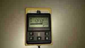
The Eberspacher heaters can be controlled with a single switch, but it’s more convenient to have some temperature control & the option of a timer. Above is an ex-BT 701 series controller, with built in 7-day programmer. Being an ex-BT van version though, it’ll only switch the heater on for 1 hour at a time.
To get around this slight niggle, I fitted a bypass toggle switch.

Remote Control
Remote Control

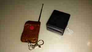
For a bit of extra convenience, I got an RF remote controlled relay module from eBay (£5).
This allows me to switch things on remotely, so I can return to a nice toasty tent while camping.
There is an official RF remote for Eberspacher heaters, but I’ve no doubt they’re hideously expensive.

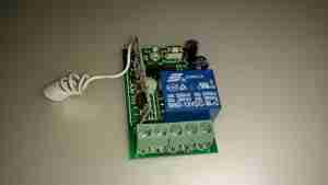
RF Receiver
RF Receiver

Here’s the receiver PCB, there’s an EEPROM & a microcontroller onboard for handling the codes the remotes send, but as the number has been scrubbed off the micro, no data there. This uses a standard RF receiver module.

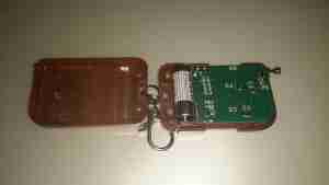
RF Remote
RF Remote

Here’s the remote itself, this uses a 12v battery instead of a 3v lithium cell. A little of a pain since these batteries can be a bit pricey.
As this RF system operates on 315MHz, it’s technically illegal in the UK, but I was unable to find a 433MHz version with the features required. Nevermind ;).

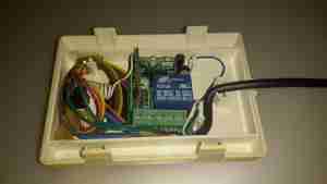
Controller Internals

Here’s the module installed in the controller casing. I have since run the antenna wire around the edge of the case to try & get the furthest range on receive. The relay contacts are just paralleled across the bypass switch, so when the relay energizes the heater fires up.
Luckily the thermostatic control portion of the 701 programmer is operational even when heating mode is not active.

Posted on Leave a comment

Duratool ZD-915 12v Conversion

Inkeeping with everything else in my shack being low voltage operated, I had planned from the outset to convert the desoldering station to 12v operation. It turns out this has been the easiest tool to convert in my shack so far.

PSU Outputs
PSU Outputs

The factory SMPS is a fairly straightforward 18v 12A unit, with only a single small oddity: the desoldering gun’s heating element is controlled from inside the supply.

Iron MOSFET
Iron MOSFET

Next to the output rectifier on the heatsink is a large MOSFET, in this case a STP60NF06 from ST Micro. This is a fairly beefy FET at 60v & 60A capacity, RDS On of <0.016Ω.
This is driven via an opto-isolator from the main logic board. I’ve not yet looked at the waveform on the scope, but I suspect this is also being PWM’d to control temperature better when close to the set point.

Iron Element Controller

Rather than fire up the soldering iron & build a new element controller circuit (Lazy Mode™), I opted to take a saw to the original power supply. I cut the DC output section of the PCB off the rest of the supply & attached this piece back to the frame of the base unit. I also added a small heatsink to the MOSFET to make sure it stays cool.

12v Power Supply
12v Power Supply

Since the fan & vacuum pump are both already 12v rated, those are connected directly to the DC input socket, that I’ve installed in place of the original IEC mains socket. The 18v for the heating element is generated by a 10A DC-DC converter, again from eBay.

Oddly, the iron itself is rated at 24v 80W, but the factory supply is only rated to 18v. I’m not sure why they’ve derated the system, but as the station already draws up to 10A from a 13.8v supply, increasing the voltage any further would start giving my DC supplies a problem, so it can stay at 18v for now.

Posted on 1 Comment

12v Temperature Controlled Soldering Iron

In my shack, 99% of my gear is all 12v powered, which is good for a few reasons:

  • Single Power Supply – This increases efficiency, as I’m only getting the losses of a single supply.
  • Safety – Mains voltages are dangerous, I’m not fond of working on such equipment.
  • Portability – I can power everything pretty much no matter were I am from a convenient car battery.
  • Convenience – Since everything is single supply, with all the same plugs, I don’t have to think about what goes where. This is more important due to my forgetfulness ;).

The one piece of equipment I regularly use that isn’t 12v is my soldering station. This is a Maplin A55KJ digital unit, which uses a 24v heating element.
While the soldering wand works OK when hooked direct to a 12v power supply (only at half power though), this removes the convenience of having temperature control.

The circuitry inside the unit is PIC microcontroller based, and doesn’t even bother rectifying the AC from the supply transformer before it’s sent to the heater. Because of this there are several reasons why I can’t just hook a DC-DC converter up to it to give it 24v.

It’s sensing the zero-crossing for the triac switch, to reduce heat dissipation, so it refuses to work at all with DC.

On looking at the Great Google, I found a project on Dangerous Prototypes, an Arduino based PID controller for soldering irons.

This requires that the soldering wand itself contains a thermocouple sensor – as the Maplin one I have is a cheap copy of the Atten 938D, it doesn’t actually use a thermocouple for temperature sensing. It appears to read the resistance of the element itself – Nichrome heating elements change resistance significantly depending on temperature.

I’ve managed to find a source of cheap irons on eBay, with built in thermocouples, so I’ve got a couple on order to do some testing with. While I wait for those to arrive, I’ve prototyped up the circuit on breadboard for testing:

Prototype
Prototype

I’ve remapped some of the Arduino pins, to make PCB layout less of a headache, but the system is working OK so far, with manual input for the sensed temperature.
I’m using an IRL520N logic-level HEXFET for the power switching, rated at 10A. As the irons only draw a max of 4.5A, this is plenty beefy enough.
To come up with the +24v supply for the heater, a small DC-DC converter will be used.

More to come when the components for the thermocouple amplifier arrive, and the soldering irons themselves!

Posted on Leave a comment

Chicom “500W” ATX PSU

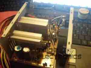
Cover Removed
Cover Removed

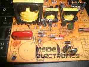
Here is a cheapo 500W rated ATX PSU that has totally borked itself, probably due to the unit NOT actually being capable of 500W. All 3 of the switching transistors were shorted, causing the ensuing carnage:

AC Input
AC Input

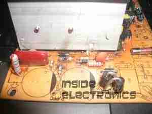
Here is the AC input to the PCB. Note the vapourised element inside the input fuse on the left. There is no PFC/filtering built into this supply, being as cheap as it is links have been installed in place of the RFI chokes.

Input Side
Input Side

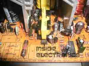
Main filter capacitors & bridge rectifier diodes. PCB shows signs of excessive heating.

Filter Caps Removed
Filter Caps Removed

Filter capacitors have been removed from the PCB here, showing some cooked components. Resistor & diode next to the heatsink are the in the biasing network for the main switching transistors.

Heatsinks Removed
Heatsinks Removed

Heatsink has been removed, note the remaining pin from one of the switching transistors still attached to the PCB & not the transistor 🙂

Transformers
Transformers

Output side of the PSU, with heatsink removed. Main transformer on  the right, transformers centre & left are the 5vSB  transformer & feedback transformer.

Output Side
Output Side

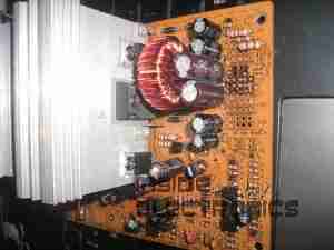
Output side of the unit, filter capacitors, choke & rectifier diodes are visible here attached to their heatsink.

Comparator
Comparator

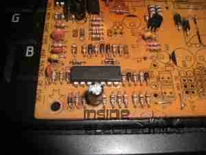
Comparator IC that deals with regulation of the outputs & overvoltage protection.

Posted on Leave a comment

Motorised Valve

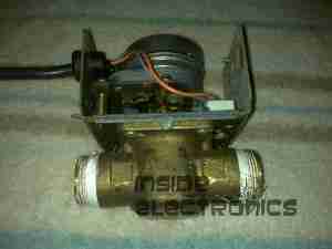
This is the internals of a motorised valve for central heating systems. Here the top is removed showing the motor & microswitch.

Left side of the valve, showing the gearing under the motor, & the valve body under the powerhead.

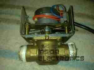
Right side of the valve, showing the sprung mechanism of the valve quadrant.

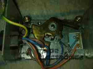
Here the motor has been removed from the powerhead, showing the microswitch & the sprung quadrant gear. This spring keeps the valve closed until the motor is energized. The motor remains energized to hold the valve open.

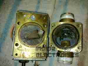
Here the valve body has been opened showing the internal components. The rubber valve rotates on the shaft, blocking the lower port of the valve when in operation.

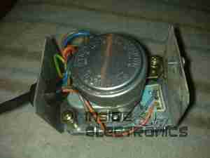
The motor’s protective cap has been removed here showing the rotor. This is a synchronous motor, of a special type for use in motorised valves. As the windings need to be continuously energized to hold the valve open, it is designed not to burn out under this load. 240v AC 50Hz, 5RPM.

Posted on Leave a comment

Hair Dryer

Housing
Housing

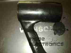
This is a 1500W hairdryer, death caused by thermal switch failure.

Switch
Switch

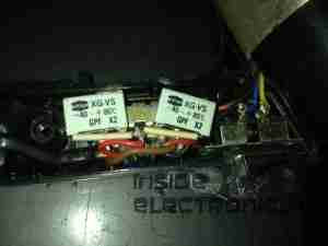
This is the switch unit. Attached are two suppression capacitors & a blocking diode. Cold switch is on right.

Heating Element
Heating Element

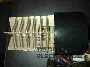
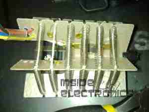
Heating element unit removed from housing. Coils of Nichrome wire heat the air passing through the dryer. Fan unit is on right.

Thermal Switch
Thermal Switch

Other side of the heating element unit, here can be seen the thermal switch behind the element winding. (Black square object).

Fan Motor
Fan Motor

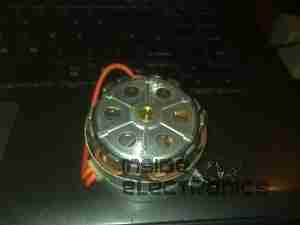
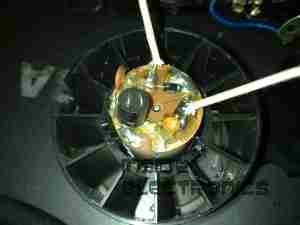
The fan motor in this dryer is a low voltage DC unit, powered through a resistor formed by part of the heating element to drop the voltage to around 12-24v. Mounted on the back of the motor here is a rectifier assembly. Guide vanes are visible around the motor, to straighten the airflow from the fan blades.

Fan
Fan

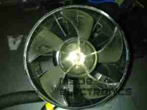
5-blade fan forces air through the element at high speed. Designed to rotate at around 13,000RPM.