Posted on Leave a comment

nb Tanya Louise Heating System – Oxide Sludge

I wrote a few weeks ago about replacing the hot water circulating pump on the boat with a new one, and mentioned that we’d been through several pumps over the years. After every replacement, autopsy of the pump has revealed the failure mode: the first pump failed due to old age & limited life of carbon brushes. The second failed due to thermal shock from an airlock in the system causing the boiler to go a bit nuts through lack of water flow. The ceramic rotor in this one just cracked.
The last pump though, was mechanically worn, the pump bearings nicely polished down just enough to cause the rotor to stick. This is caused by sediment in the system, which comes from corrosion in the various components of the system. Radiators & skin tanks are steel, engine block cast iron, back boiler stainless steel, Webasto heat exchanger aluminium, along with various bits of copper pipe & hose tying the system together.
The use of dissimilar metals in a system is not particularly advisable, but in the case of the boat, it’s unavoidable. The antifreeze in the water does have anti-corrosive additives, but we were still left with the problem of all the various oxides of iron floating around the system acting like an abrasive. To solve this problem without having to go to the trouble of doing a full system flush, we fitted a magnetic filter:
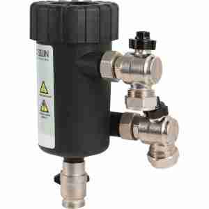
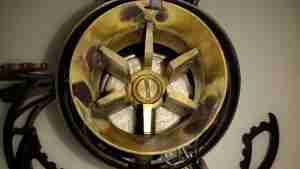
Mag Filter
Mag Filter

This is just an empty container, with a powerful NdFeB magnet inserted into the centre. As the water flows in a spiral around the magnetic core, aided by the offset pipe connections, the magnet pulls all the magnetic oxides out of the water. it’s fitted into the circuit at the last radiator, where it’s accessible for the mandatory maintenance.
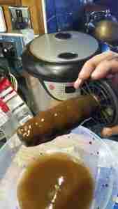
Sludge
Sludge

Now the filter has been in about a month, I decided it would be a good time to see how much muck had been pulled out of the circuit. I was rather surprised to see a 1/2″ thick layer of sludge coating the magnetic core! The disgusting water in the bowl below was what drained out of the filter before the top was pulled. (The general colour of the water in the circuit isn’t this colour, I knocked some loose from the core of the filter while isolating it).

If all goes well, the level of sludge in the system will over time be reduced to a very low level, with the corrosion inhibitor helping things along. This should result in much fewer expensive pump replacements!
Posted on Leave a comment

nb Tanya Louise Heating Upgrades – Matrix Install


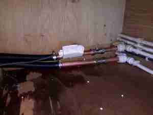
Heating Circuit
Heating Circuit

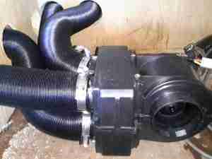
Here the pipework feeding the matrix of the blower unit has been tapped into the heating circuit, the first radiator on the loop is just out of shot to the right, this is all tucked away under the bed in one of the cabins. The pipestat is attached to the flow from the boiler, this will switch on the blower once hot water starts flowing through the system. Isolation valves have been fitted to make the inevitable maintenance of the matrix unit easier, as the system is pressurised to 14PSI, dropping the pressure out of the system without making quite a mess is difficult.

Heater Matrix & Ducting

The heater itself is mounted on the other side of a wooden partition in the small space left under a shelf. This made installing the unit like trying to plumb in a radiator through a letterbox ;). 4 60mm ducts snake off to the vents mounted in the wall.

Water Connections
Water Connections

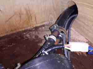
The hot water hoses appear through a hole in the timber to connect to the matrix unit, with some 15mm pipe in between as reducers from the 3/4″ hose to the 1/2″ attached to the matrix itself. The blower is wired in low speed mode only, as running it any faster makes far too much noise from the vents.

As a heating solution, this unit works well onboard. Within a 10 minutes of the diesel heater firing up, the blower automatically comes on thanks to the thermostat, and blows plenty of hot air into the saloon to keep the cold at bay.

Posted on Leave a comment

Camping Gear – Optimus Nova Multifuel Stove

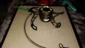
Stove
Stove

For as long as I can remember I’ve been using Trangia-type alcohol fuelled stoves when I go camping, even though these have served my needs well they’re very limited & tend to waste fuel. I did some looking around for Paraffin/Kerosene fuelled stoves instead, as I already have this fuel on site.
I found very good reviews on the Optimus Nova above, so I decided to go for this one.

This stove can run on many different fuel types, “white gas” (petrol without any vehicle additives) Diesel, Kerosene & Jet A.

Burner
Burner

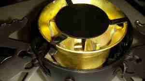
Here’s the “hot end” of the device, the burner itself. This is made in two cast Brass sections, that are brazed together. The fuel jet can be just seen in the centre of the casting.

Fuel Pump
Fuel Pump

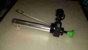
The fuel bottle is pressurised with a pump very similar to the ones used on Paraffin pressure lamps, so I’m used to this kind of setup. The fuel dip tube has a filter on the end to stop any munge gumming up the valves or the burner jet.

Pre-Heating
Pre-Heating

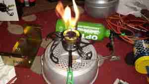
As with all liquid-fuelled vapour burners, it has to be preheated. There’s a fibreglass pad in the bottom of the burner for this, and can be soaked with any fuel of choice. The manual states to preheat with the fuel in the bottle, but as I’m using Paraffin, this would be very smoky indeed, so here it’s being preheated with a bit of Isopropanol.
The fuel bottle can be seen in the background as well, connected to the burner with a flexible hose. The main burner control valve is attached to the green handle bottom centre.

Simmer
Simmer

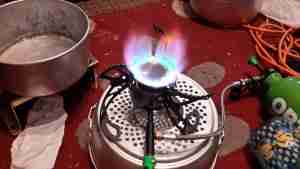
Once the preheating flame has burned down, the fuel valve can be opened, here’s the stove burning Paraffin on very low simmer. (An advantage over the older alcohol burners I’m used to – adjustable heat!)

Full Power!
Full Power!

Opening the control valve a couple of turns gives flamethrower mode. At full power, the burner is a little loud, but no louder than my usual Paraffin pressure lamps.

Flame Pattern
Flame Pattern

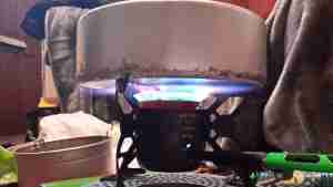
With a pan of water on the stove, the flame covers the entire base of the pan. Good for heat transfer. This stove was able to boil 1L of water from cold in 5 minutes. A little longer than the manual states, but that’s still much quicker than I’m used to!

Fuel Jet
Fuel Jet

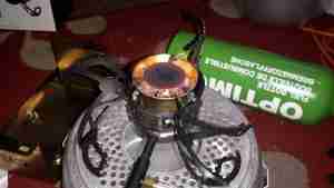
The top of the burner opens for cleaning, here’s a look at the jet in the centre of the burner. The preheating pad can be seen below the brass casting.

Posted on Leave a comment

nb Tanya Louise – Compressor Install

Compressed air is a rather useful power source, especially when all maintenance is done by the on board crew instead of by boatyards.

Screwfix had a good deal on a 50L 3.5CFM air compressor, to save space this has been permanently mounted in a free space & air will be piped to where it is needed from a central point.

Because of the total height of the machine, the compressor itself has been unbolted from the tank, a copper line connecting the two back together at a larger distance.

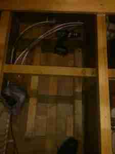
Bearers
Bearers

In one of the very few free spaces available, under a bunk. A pair of timbers has been screwed to the floor to support the tank.

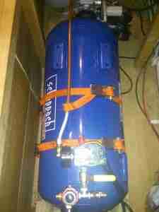
Tank Installed
Tank Installed

The tank is strapped to the wooden supports with a pair of ratchet straps, the compressor itself can be seen just behind the tank. The copper line on the top of the tank is going back to be connected to the compressor outlet.

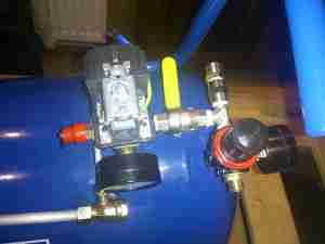
Air Fittings
Air Fittings

Compressor control remains on top of the tank, the pressure switch & relief valve centre. After an isolation valve, the feed splits, the regulator installed will be feeding the air horn with 20PSI, replacing the existing automotive-style 12v air pump. The currently open fitting will be routed to a quick connect on the bulkhead. This will be accessible from the front deck, an air hose can be fitted to get a supply anywhere on board.

More to come when the rest of the system gets installed!

73s for now.

Posted on 4 Comments

Audi TT Roof Hydraulics

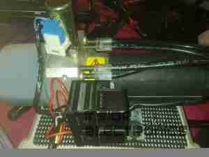
Pump
Pump

This is the hydraulic system from an Audi TT that would power the soft top. Here is the hydraulic pump unit. Oil Tank is on the left. Power is 12v DC at ~20A

Cylinders
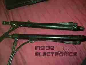
Cylinders

The pair of hydraulic cylinders that attached to the roof mechanism.

Limit Switch
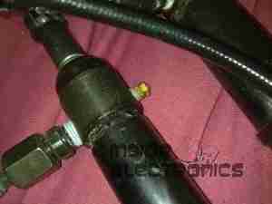
Limit Switch

One of the cylinders has a limit switch built in. The brass bolt coming out of the side of the head is one contact. The other contact is the cylinder body.

Hose
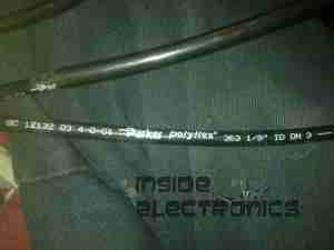
Hose

Marking on the hoses. This is Parker Polyflex hydraulic hose. 1/8″ ID.

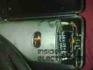
Motor
Motor

Drive motor for the hydraulic pump. Standard DC permanent magnet motor.

Motor Suppression
Motor Suppression

Motor power terminals & suppression capacitors. As the reversing relays actually short the motor out when de-energized, there is a lot of arcing at the brushes without some suppression.

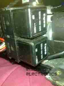
Reversing Relays
Reversing Relays

Reversing relay stack. Each relay is a SPDT configuration. The pair are arranged as a DPDT bank to reverse the motor, depending on which relay is energized.

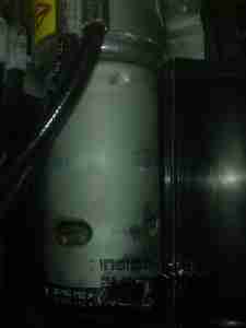
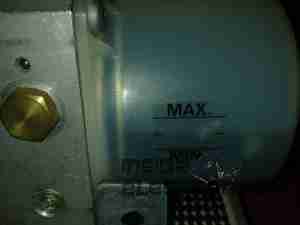
Tank
Tank

Detail of the oil tank showing the level markings.

Power Valve
Power Valve

Solenoid valve on top of the unit. This valve provides full pump pressure to the cylinders when energized.