Posted on Leave a comment

nb Tanya Louise Hydraulic Generator

Hydraulic Generator Unit

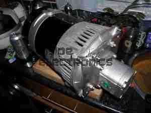
To accompany the previous two posts about hydraulic generators & their components, here is the actual generator unit itself.

Rated at 8.5kVa 230v AC, this will providea mains supply while the narrowboat is away from her home mooring.

This unit will be attached to the side of the hull in the engine room on rubber vibration isolation mounts, behind the main hydraulic oil tank & is driven from the small gear pump attached to the back of the main propulsion hydraulic pump unit.
Operating pressure is 175 bar, 21L/m flow rate to achieve the 3,000RPM rotor speed for 50Hz mains frequency.
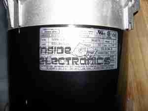
Generator Specifications
Posted on 4 Comments

Audi TT Roof Hydraulics

Pump
Pump

This is the hydraulic system from an Audi TT that would power the soft top. Here is the hydraulic pump unit. Oil Tank is on the left. Power is 12v DC at ~20A

Cylinders
Cylinders

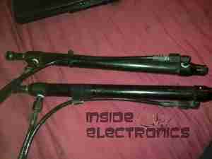
The pair of hydraulic cylinders that attached to the roof mechanism.

Limit Switch
Limit Switch

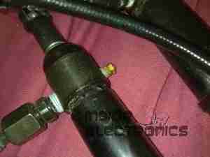
One of the cylinders has a limit switch built in. The brass bolt coming out of the side of the head is one contact. The other contact is the cylinder body.

Hose
Hose

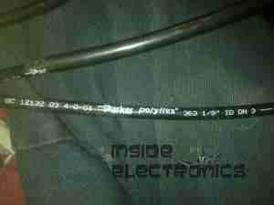
Marking on the hoses. This is Parker Polyflex hydraulic hose. 1/8″ ID.

Motor
Motor

Drive motor for the hydraulic pump. Standard DC permanent magnet motor.

Motor Suppression
Motor Suppression

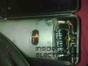
Motor power terminals & suppression capacitors. As the reversing relays actually short the motor out when de-energized, there is a lot of arcing at the brushes without some suppression.

Reversing Relays
Reversing Relays

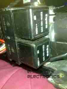
Reversing relay stack. Each relay is a SPDT configuration. The pair are arranged as a DPDT bank to reverse the motor, depending on which relay is energized.

Tank
Tank

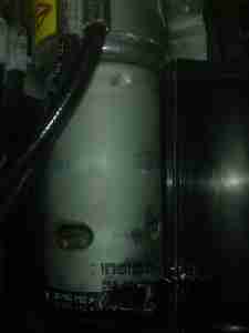
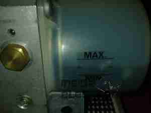
Detail of the oil tank showing the level markings.

Power Valve
Power Valve

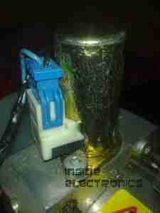
Solenoid valve on top of the unit. This valve provides full pump pressure to the cylinders when energized.