Posted on Leave a comment

USB-IDE/SATA Adaptor

Front
Front

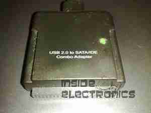
This is a device to use an IDE or SATA interface drive via a USB connection. Here is the front of the device, IDE interface at the bottom, 2.5″ form factor.
PCB Top
PCB Top

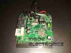
PCB removed from the casing. USB cable exits the top, 12v DC power jack to the left.
SATA interface below the DC Jack.
Molex connector below SATA is the power output for the drive in use. This unit has a built in 5v regulator.
PCB Bottom
PCB Bottom

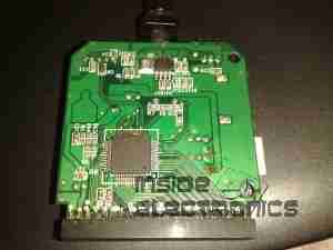
Bottom of the PCB showing the interface IC.
Drive Adaptor
Drive Adaptor

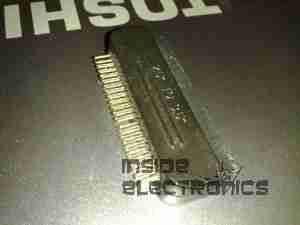
Adaptor to plug into the 44-pin 2.5″ form factor IDE interface on the adaptor, converts to standard 40-pin 3.5″ IDE.
Power Cable
Power Cable

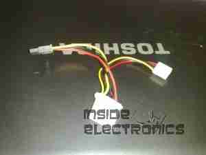
Power pigtail with standard Molex & SATA power plugs.
Posted on Leave a comment

IDE Zip Drive

Top
Top

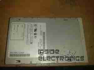
An old IDE interface Zip drive. This fits in a standard 3.5″ bay.

Cover Removed
Cover Removed

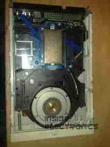
Top cover removed from the drive, IDE & power interfaces at the top, in centre is the eject solenoid assembly & the head assembly. Bottom is the spindle drive motor.

Head Assembly
Head Assembly

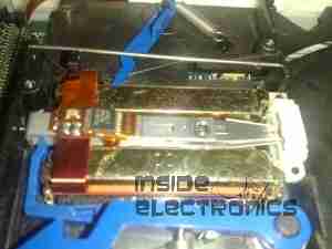
Head assembly with the top magnet removed. Voice coil is on the left, with the head preamp IC next to it. Head chips are on the end of the arm inside the parking sleeve on the right. Blue lever is the head lock.

Controller
Controller

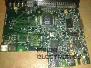
Controller PCB removed from the casing.

Spindle Motor
Spindle Motor

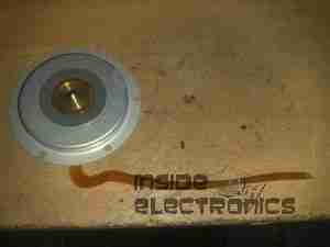
Spindle motor. This is a 3-phase DC brushless type motor. Magnetic ring on the top engages with the hub of the Zip disk when insterted into the drive.

Magnets
Magnets

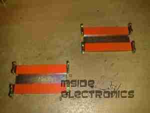
Magnets that interact with the voice coil on the head assembly.

Head Armature
Head Armature

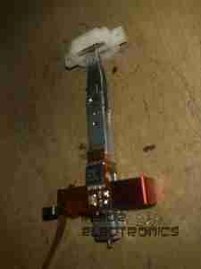
Head armature assembly removed from the drive. The arm is supported by a pair of linear bearings & a stainless steel rod.