Here is a followup from the 1.5W laser module post.
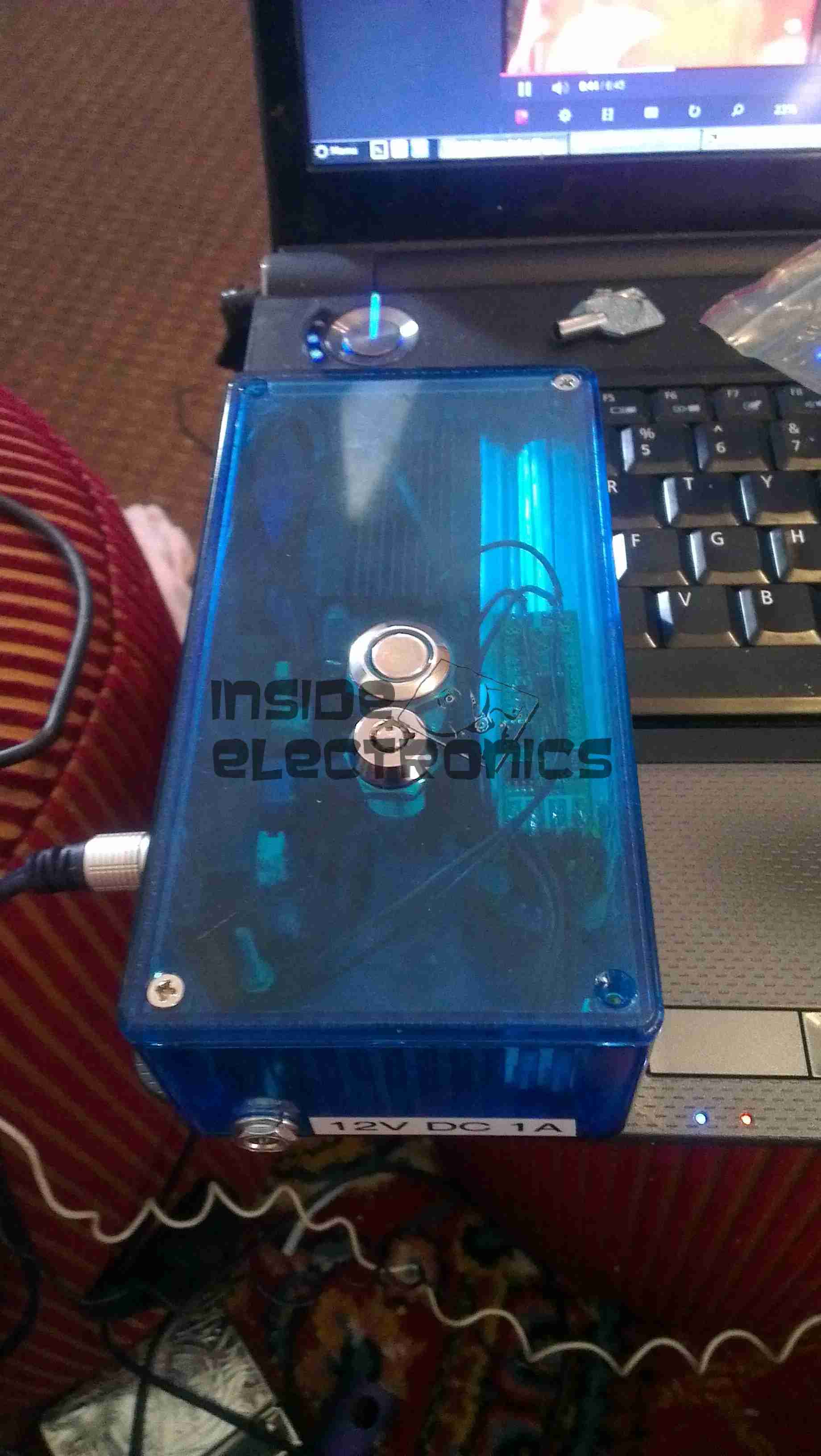
The module has been fitted into a housing, with a 2.2Ah Li-Poly battery pack. Charging is accomplished with an external 12.6v DC power supply.
Above can be seen the pair of switches on the top, the keyswitch must be enabled for the laser to fire.
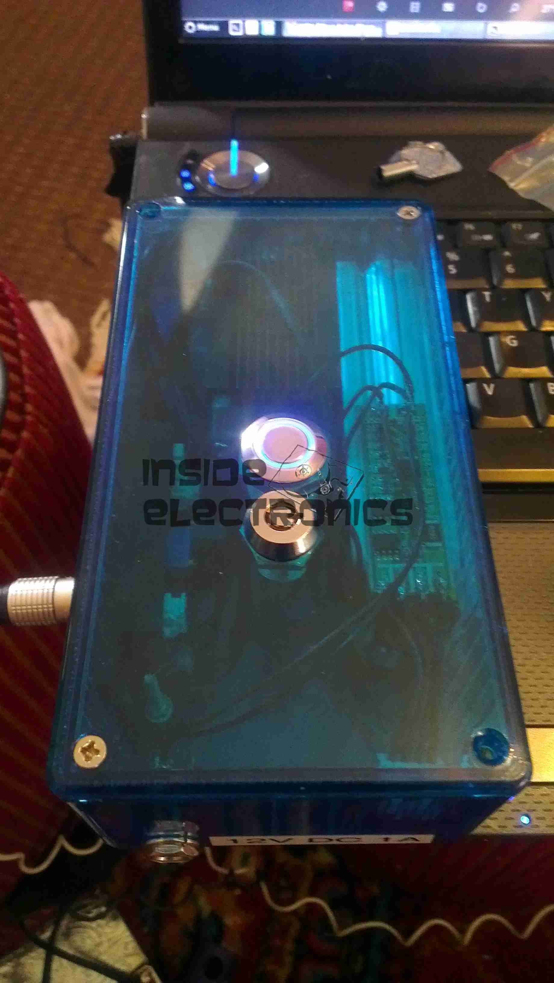
Armed
When armed, the ring around the push button illuminates blue, as a warning that the unit is armed.
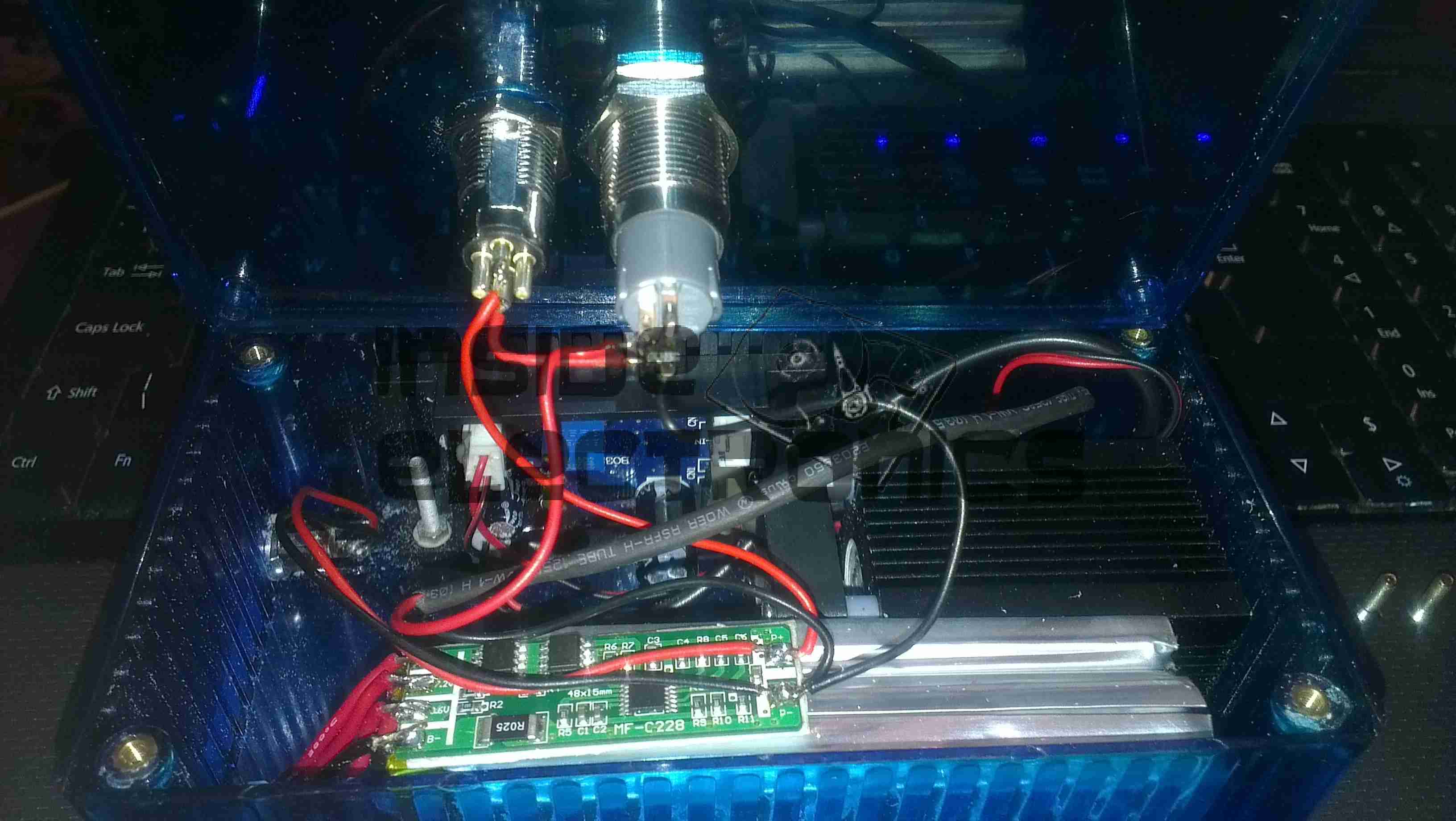
Switch Wiring
Inside the unit. The Li-Poly battery pack is at the bottom, with it’s protection & charging circuitry on the top. The switches are wired in series, with the LED connected to illuminate when the keyswitch is turned to the ON position.
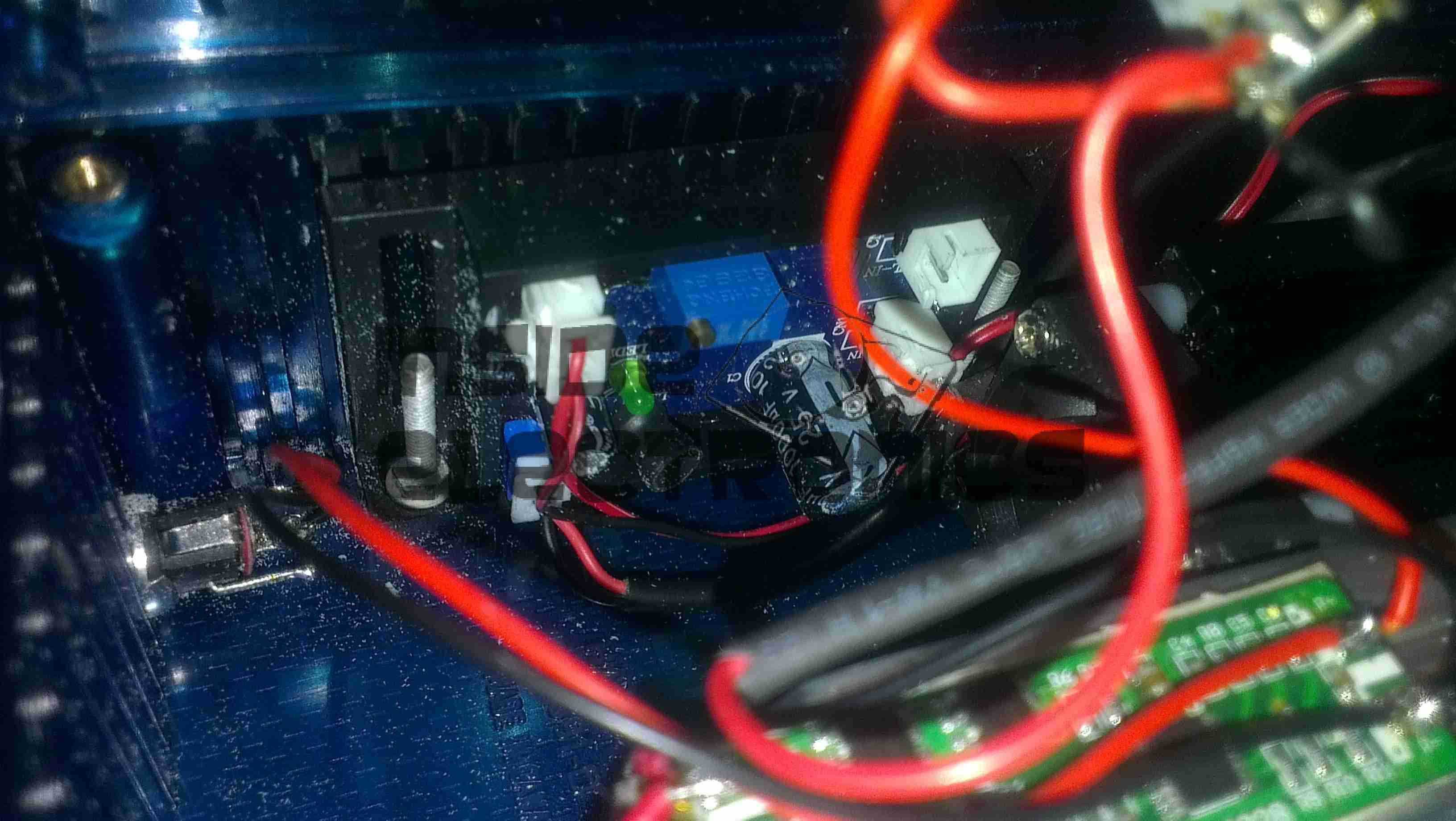
Laser Driver
The push button applies power to the laser driver module, which regulates the input power to safely drive the semiconductor laser in the aluminium heatsink housing.
Finally, some protection for my Raspberry Pi! The PCB fit is slightly loose, but that was quickly sorted with the application of a couple of spots of hot glue in the corners.
Unfortunately, the case is a couple of mm too small to fit the main board from the Pico Projector inside, so I won’t be butchering that into the case with the Pi as yet. What is required is an interface to the display engine from the Pi’s DSI interface.
Pi Cased Up
The pi all boxed. up. The only thing that this case would now require is a lightpipe to direct the LED’s light to the openings in the case, as they are very difficult to see at present.
This unit was bought from eBay to experiment with Magnetic Stripe cards, for little money. This unit is capable of reading & writing all 3 tracks, & both Hi-Co & Lo-Co card types.
Interfaced to a PC through USB, this has a built in PL2303 USB-Serial IC & requires 3A at 9v DC to operate.
The 3 Indicator LEDs on the top of the unit can be toggled by the included software for Power/OK/Fault condition signalling.
Unit Bottom
Bottom of the unit with the model labels.
Model Label
Closeup of the model label & serial number.
PCB Bottom
Here the bottom cover has been removed, showing the main PCB. The pair of large ICs bottom center interface with the magnetic heads. The IC above them has had the markings sanded off.
USB-Serial Interface
Closeup of the Prolific PL-2303 USB-Serial converter IC.
PCB Top
Here the connections to the R/W heads are visible, current limiting resistors at the left for the write head, a pair of signal relays, a pair of optoisolators & a LM7805 linear voltage regulator.
LEDs
Here is the trio of indicator LEDs on a small sub-board.
Frame Bottom
The PCB has been removed from the main frame here, the only component visible is the rotary encoder.
Rotary Encoder
The rotary encoder has a rubber wheel fitted, which reads the speed of the card as it is being swiped for writing. This allows the control logic to write the data to the stripe at the correct rate for the speed of the card. This allows the unit to write cards from 5-50 inches per second speed.
The Write head is directly behind the rubber pressure roller.
Read/Write Heads
Here you can see the R/W head assembly. The write head is on the right, read on the left. When a card is written to, it immediately gets read by the second head for verification.
This is a cheap Sigma branded keychain photoframe. User buttons for power & selecting photos are on the left.
There are two white LEDs on the bottom edge that function as a torch as well.
Display
Front of the unit removed, showing the LCD module. The USB jack is bottom left, next to the pair of white LEDs & above that is the 32kHz watch crystal that the CPU uses for timekeeping.
Back Removed
Here the back has been removed showing the 3.7v Li-Ion cell used to provide power.
Display Folded Back
Here the display has been removed from the PCB exposing the chipset.
Chipset
Here the CPU blob-top chip & a flash memory IC are visible. The CPU is a Sitronix ST2205U.
Here is a Inductive charger designed for the Nintendo DSi. Cheap Chinese build, but it does work!
Overview
Top has been removed from the unit here. Most prominent in the centre is a solid steel bar, simply there to give the device some weight.
Pair of Tri-colour LEDs at the front indicates charging status.
Induction coil is on the left, with the controller & oscillator PCB at the top.
PCB Closeup
Closeup of the PCB, ICs have had their markings ground off.
Coil
Induction coil. This couples power into a coil built into a special battery, supplied with the base, to charge it when the DSi is placed on the dock.
Label
Information Label on the base.
Power Input
Standard DSi charger port, connects to the charger you get with the DSi. Power switch is on the right.
Here is a cheap no brand hot laminator. This pulls the paper, inside a plastic pouch through a pair of heated rollers to seal it.
Heater
Top removed, heater assembly visible. PCB attached to the top cover holds LEDs to indicate power & ready status.
SwitchThermostat
Here is the thermostat & thermal fuse, the thermostat switching the indicator on the front panel to tell the user when the unit is up to temperature. This has a self regulating thermostat. Thermal fuse inside the heat resistant tubing is to protect against any failure of the heater.
Motor
5 RPM motor that turns the rollers through a simple gear system.
This is detailing my portable multi-purpose power pack of my own design. Here is an overview, mainly showing the 4Ah 12v Ni-Cd battery pack.
Front Panel Right
Panel Features – Bottom: Car cigar lighter socket, main power keyswitch. Top: LED toggle switch, provision for upcoming laser project, Red main Power LED, 7A circuit breaker.
Front Panel Left
Top: Toggle switch serving post terminals, USB Port.
Post terminals supply unregulated 12v for external gadgets. USB port is standard 5v regulated for charging phones, PDAs etc.
Bottom: Pair of XLR connectors for external LED lights. Switches on their right control power & the knob controls brightness.
Additions are being made to this all the time, the latest being a 2W laser diode driver. Update to come soon!
This is an old legacy wireless mouse from Logitech. This uses a ball rather than optical technology.
Bottom
Bottom of the mouse, showing the battery cover & the mouse ball.
PCB Bottom
Top removed from the mouse, showing the PCB inside. The smaller PCB on the left supports the microswitches for the buttons & mouse wheel.
Switches
Closeup of small PCB showing the microswitches & the IR LED & phototransistor pair for the mouse wheel encoder.
Main PCB
View of main PCB, with interface IC lower right. Pair of quartz crystals provide clocking for the transmitter & internal µC.
Battery contacts are on lower left of the PCB. At the top are the IR pairs for the X & Y axis of the mouse ball.
Encoder Pairs
Closeup of the pairs of IR LEDs & phototransistors that make up the encoders for X/Y movement of the mouse, together with the slotted wheels in the mouse base that rotate with the ball. Steel wire around the smaller PCB is the antenna.
Here is an old Belkin Wireless G network card. This is a PCMCIA version.
Bottom Label
Here is the bottom of the device, with all the details.
Antenna
Plastic antenna cover removed, showing the pair of 2.4GHz etched antennae. There is a pair of LEDs on the upper left of the PCB showing activity & link status.
PCB
Overall view of the PCB, antennae on the left, RF chipset in centre, WiFi controller IC on right, and PCMCIA socket on far right. Can below wireless controller is a quartz crystal for the clock.
Chipset
Closeup of the chipset, a Ralink RT2560F wireless controller on the right & a RT2525L transceiver on the left.
Here is a Bosch 14.4v Professional cordless drill/driver, recovered from a skip!
It was thrown away due to a gearbox fault, which was easy to rectify.
Internals
Here is the drill with the side cover removed, showing it’s internal parts. The speed controller is below the motor & gearbox here. The unit at the top consists of a 12v DC motor, coupled to a 4-stage epicyclic gearbox unit, from which can be selected 2 different ratios, by way of the lever in the centre of the box. This disables one of the gear stages. There is a torque control clutch at the chuck end of the gearbox, this was faulty when found.
Motor
Here is the drive motor disconnected from the gearbox, having a bayonet fitting on the drive end.
Drive Gear
This is the primary drive gear of the motor, which connects with the gearbox.
Cooling Fan
The motor is cooled by this fan inside next to the commutator, drawing air over the windings.
Gearbox
This is the gearbox partially disassembled, showing the 1st & second stages of the geartrain. The second stage provides the 2 different drive ratios by having the annulus slide over the entire gearset, disabling it entirely, in high gear. The annulus gears are a potential weak point in this gearbox, as they are made from plastic, with all other gears being made of steel.
Charger
Here is the charging unit for the Ni-Cd battery packs supplied with the drill. The only indicator is the LED shown here on the front of the unit, which flashes while charging, & comes on solid when charging is complete. Charge termination is by way of temperature monitoring.
Transformer
Here the bottom of the charger has been removed, showing the internal parts. An 18v transformer supplies power to the charger PCB on the left.
Charger PCB
This is the charger PCB, with a ST Microelectronics controller IC marked 6HKB07501758. I cannot find any information about this chip.
Battery Pack Internals
Here is a battery pack with the top removed, showing the cells.
Temperature Sensor
This is the temperature sensor embedded inside the battery pack that is used by the charger to determine when charging is complete.
This is an old USB 1.1 hub that was recently retired from service on some servers. Top of the unit visible here.
Bottom Label
Bottom label shows that this is a model F5U021 hub, a rather old unit.
PCB Front
PCB is here removed from the casing, Indicator LEDs along the bottom edge of the board, power supply is on the left. Connectors on the top edge are external power, USB host, & the 4 USB outputs. Yellow devices are polyswitch fuses for the 500mA at 5v each port must supply.
USB Hub IC
This is the USB Hub Controller IC, which is a Texas Instruments TUSB2046B device. Power filter capacitors next to the USB ports are visible here also, along with 2 of the polyswitches.
Power Supply
The power supply section of the unit, which supplies regulated 5v to the ports, while supplying regulated 3.3v to the hub controller IC. Large TO-220 IC is the 5v regulator. Smaller IC just under the power selector switch is the 3.3v regulator for the hub IC. The switch selects between Host powered or external power for the hub.
Here is a cheap chinese made flash drive given out for free by Westlaw UK. Capacity 512MB
PCB
Here is the PCB removed from the casing, USB connector on the left, followed by the clock crystal for the flash controller, a CBM2092, which is a Chipsbank part. 512MB flash memory IC, unknown maker. Access LED on far right of the board.
This is a device designed to reset Epson brand ink cartridges that are reportedly out of ink, so they again report full to the printer Here is the front of the unit, with the guide for attaching to a cartridge.
PCB Back
Back of the device removed. 3 button cells provide power to the PCB. Indicator LED sticks out of the top of the device for reset confirmation.
Row of pads on far left edge of the PCB are presumably a programming header for the uC on the other side of the board.
PCB Front
Here is the front of the PCB, main feature being the grid of pogo pins to connect to the cartridge chip. IC on lower right of that is a MSP430F2131 uController, a Texas Instruments part.
The IC directly to the left of the pogo pin bed is a voltage regulator, to step down the ~4.5v of the batteries down to the ~3.3v that the uC requires.
Here is a phone from the mid 90s, the Ericsson GA628. Here visible is the front of the unit with keypad, & single line monochrome LCD for number display.
Battery & Rear
Here the battery is removed from the phone, showing the SIM card socket. At the top under the antenna stub is the socket for an external antenna.
Front Removed
Here the front is removed from the phone, PCB on left, rear of keypad on right. Microphone is at bottom of keypad, with speaker at the top. Top right of the PCB is the ringer buzzer, left is shield for RF amplifier.
Main PCB
Here is the back of the main PCB, RF sections on left & centre. Processing & memory on right.
Battery
This phone had a Ni-Mh battery, before Li-Ion batteries were introduced.
LCD
The LCD from the front of the phone is shown here. A simple dot matrix single line unit.
An ICL barcode scanner from the 80s is shown here. This is the top of the unit with cover on.
Cover Removed
Plastic cover removed from the unit showing internal components. Main PSU on left, scan assembly in center. Laser PSU & Cooling fan on right. Laser tube at top.
Scan Motor
Closeup of laser scan motor. This unit scans the laser beam rapidly across the glass plate to read the barcode.
Controller PCB
View of the bottom of the unit, showing the controller PCB in the centre.
Scan Motor Driver
The 3-phase motor driver circuit for the scan motor. 15v DC powered.
Laser Unit
This is the laser unit disconnected from the back of the scanner. HT PSU is on right hand side, beam emerges from optics on left.
Laser Unit Label
This unit is date stamped 1987. The oldest laser unit i own.
Rear of HT PSU. Obviously the factory made a mistake or two 🙂
Laser Tube Mounting
Top cover removed from the laser unit here shows the 1mW He-Ne tube. Manufactured by Aerotech.
AeroTech He-Ne Tube
Tube label. Manufactured July 1993. Model LT06XR.
Plasma
Here the tube has been removed from it’s mount to show the bore down the centre while energized.
OC Mirror
OC end of the tube shown here lasing.
Beam
Beam output from the optics on the laser unit.
Tube Optics
Optics built into the laser unit. Simple turning mirror on adjustable mount & collimating lens assembly.
Scan Lines
Kind of hard to see but the unit is running here & projecting the scan lines on the top glass.
Laser Tube Mounting
Laser tube mounting. A combo of spring clips & hot glue hold this He-Ne tube in place
Tip Jar
If you’ve found my content useful, please consider leaving a donation by clicking the Tip Jar below!
All collected funds go towards new content & the costs of keeping the server online.