Effects of Magnetic Fields on He-Ne Laser Operation
If you open the case on a higher power (and longer) He-Ne laser head or one that is designed with an emphasis on precision and stability, you may find a series of magnets or electromagnetic coils in various locations in close proximity to the He-Ne tube. They may be distributed along its length or bunched at one end; with alternating or opposing N and S poles, or a coaxial arrangement; and of various sizes, styles, and strengths.
Magnets may be incorporated in He-Ne lasers for several reasons including the suppression of IR spectral lines to improve efficiency (such as it is!) and to boost power at visible wavelengths, to control its polarization, and to split the optical frequency into two closely spaced components. There are no doubt other uses as well.
The basic mechanism for the interaction of emitted light and magnetic fields is something called the ‘Zeeman Effect’ or ‘Zeeman Splitting’. The following brief description is from the “CRC Handbook of Chemistry and Physics”:
“The splitting of a spectrum line into several symmetrically disposed components, which occurs when the source of light is placed in a strong magnetic field. The components are polarized, the directions of polarization and the appearance of the effect depending on the direction from which the source is viewed relative to the lines of force.”
Magnetic fields may affect the behaviour of He-Ne tubes in several ways:
- He-Ne tubes with long discharge paths will tend to amplify the (generally unwanted) IR wavelengths (probably the one at 3.39µm which is one of the strongest, if not the strongest of all lines) at the expense of the visible ones. The purpose of these magnets is to suppress spectral lines that do not contribute to the desired lasing wavelength (usually the visible red 632.8nm for these long tubes). As a result of the Zeeman Effect, if a gas radiates in a magnetic field, most of its spectral lines are split into 2 or sometimes more components. The magnitude of the separation depends on the strength of the magnetic field and as a result, if the field is also non-uniform, the spectral lines are broadened as well because light emitted at different locations will see an unequal magnetic field. These ‘fuzzed out’ lines cannot participate in stimulated emission as efficiently as nice narrow lines and therefore will not drain the upper energy states for use by the desired lines. The magnitude of the Zeeman splitting effect is also wavelength dependent and therefore can be used to control the gain of selected spectral lines (long ones are apparently affected more than short ones on a percentage basis).The Doppler-broadened gain bandwidth of neon is inversely related to wavelength. At 632.8nm (red) it is around 1.5 to 1.6 GHz; at 3,391nm (the troublesome IR line), it is only around 310MHz. A magnetic field that varies spatially along the tube will split and move the gain curves at all wavelengths equally by varying amounts depending on position. However, a, say, 100 or 200MHz split and shift of the gain curve for the 632.8nm red transition won’t have much effect, but it will effectively disrupt lasing for the 3,391nm IR transition.Without the use of magnets, the very strong neon IR line at 3.39µm would compete with (and possibly dominate over) the desired visible line (at 632.8nm) stealing power from the discharge that would otherwise contribute to simulated emission at 632.8 nm. However, the IR isn’t wanted (and therefore will not be amplified since the mirrors are not particularly reflective at IR wavelengths anyhow). Since the 3.39nm wavelength is more than 5 times longer than the 632.8 nm red line, it is affected to a much greater extent by the magnetic field and overall gain and power output at 632.8nm may be increased dramatically (25 percent or more). The magnets may be required to obtain any (visible) output beam at all with some He-Ne tubes (though this is not common).
The typical higher power Spectra-Physics He-Ne laser will have relatively low strength magnets (e.g., like those used to stick notes to your fridge) placed at every available location along the exposed bore along the sides of the L-shaped resonator frame. They will alternate N and S poles pointing toward the bore. Interestingly, on some high mileage tubes, brown crud (which might be material sputtered off the anode) may collect inside the bore – but only at locations of one field polarity (N or S, whichever would tend to deflect a positive ion stream into the wall). The crud itself doesn’t really affect anything but is an indication of long use. And on average, tubes with a lot of brown crud may be harder to start, and require a higher voltage to run, and have lower output power.
I do not know how to determine if and when such magnets are needed for long high power He-Ne tubes where they are not part of an existing laser head. My guess is that the original or intended positions, orientations, and strengths, of the magnets were determined experimentally by trial and error or from a recipe passed down from generation to generation, and not through the use of some unusually complex convoluted obscure theory. 🙂
The only thing I can suggest other than contacting the manufacturer (like any manufacturer now cares about and supports He-Ne lasers at all!) is to very carefully experiment with placing magnets of various sizes and strengths at strategic locations (or a half dozen such locations) to determine if beam power at the desired wavelength is affected. Just take care to avoid smashing your flesh or the He-Ne tube when playing with powerful magnets. Though the magnets used in large-frame He-Ne lasers with exposed bores aren’t particularly powerful, to produce the same effective field strength at the central bore of an internal mirror He-Ne tube may require somewhat stronger ones, though even these needn’t be the flesh squashing variety. And, magnets that are very strong may affect other characteristics of the laser including polarization, and starting and running voltage. Enclosing the He-Ne tube in a protective rigid sleeve (e.g., PVC or aluminium) would reduce the risk of the latter disaster, at least. 🙂 If there is going to be any significant improvement, almost any arrangement of 1 or 2 magnets should show some effect.
There may be an immediate effect when adding or moving a magnet. However, to really determine the overall improvement in (visible) output power and any reduction in the variation of output power with mode sweep, the laser should be allowed to go through several mode sweep cycles for 3.39 µm. These will be about 5.4 times the length of the mode sweep for 632.8 nm.
CAUTION: For soft-seal laser tubes in less than excellent health (i.e., which may have gas contamination), changing the magnet configuration near the cathode may result in a slow decline in output power (over several hours) which may or may not recover. I have only observed this behaviour with a single REO one-Brewster tube, but there seems to be no other explanation for the slow decline to about half the original power, and then subsequent slow recovery with extended run time after the magnets were removed entirely. Possibly simply leaving the magnets in the new configuration would have eventually resulted in power recovery, but at the time the trend was not encouraging.
(From: Lynn Strickland (stricks760@earthlink.net).)
“They’ve pretty much nailed the 3.39 micron problem on red He-Ne tubes these days so magnets really aren’t needed on them. Even the new green tubes don’t have much of a problem – especially since the optic suppliers have perfected the mirror coatings. All of the good green mirrors are now done with Ion Beam Sputtering (IBS), as opposed to run-of-the-mill E-Beam stuff.However, you’ll probably see a benefit from magnets to suppress the 3.39µm line on the older He-Ne tubes.”
- While most inexpensive He-Ne tubes that produce linearly polarized light do so because of an internal Brewster plate and lasers with external mirrors have Brewster windows on the ends of the plasma tube, it is also possible to affect the polarization of the beam with strong magnets again using the Zeeman Effect.Where the capillary of the plasma tube is exposed as with many older lasers, and the magnets can be placed in close proximity to the bore, their strength can be much lower. A few commercial lasers (like the Spectra-Physics model 132) offered a polarization option which adds a magnet assembly alongside the tube. In this case, what is required is a uniform or mostly uniform field of the appropriate orientation rather than one that varies as for IR spectral line suppression though both of these could be probably be combined. However, the polarization purity with this approach never came anywhere close to that using a simple Brewster window or plate, found in all modern polarized He-Ne lasers.Also see the section: Unrandomizing the Polarization of a Randomly Polarized HeNe Tube.
- Two-frequency He-Ne lasers are used in precision interferometers for making measurements to nanometer accuracy. With these, the Zeeman effect is exploited to split the output of a single frequency He-Ne laser into a pair of closely spaced optical frequencies so that a difference or “split” frequency can be obtained using a fast photodiode. The most common are axial Zeeman lasers that use a powerful magnetic field oriented along the axis of the tube. For these, the “split” frequency is typically between 1.5 and 7.5 MHz (though it could be much lower but not much higher). Transverse Zeeman lasers use a moderate strength field oriented across the tube and have split frequencies in the 100s of kHz range. To stabilize these lasers, either a heater or piezo element is provided to precisely control cavity length.
In principle, varying fields from electromagnets could be used for intensity, polarization, and frequency modulation. I do not know whether any commercial He-Ne lasers have been implemented in this manner.
But if magnets were not originally present, the only situation where adding some may make sense is for older longer or “other colour” He-Ne tubes where a series of weak magnets may actually boost output power by 10 to 25 percent or more. On the other hand, most non-Zeeman stabilized He-Ne lasers do NOT like magnets at all. Even a relatively weak stray magnetic field from nearby equipment may result in a significant change in behaviour. However, unless ferrous metals are used in the laser’s construction, any change will likely not be permanent.
Typical Magnet Configurations
Here are examples of some of the common arrangements of magnets that you may come across. In addition to those shown, magnets may be present along only one side of the tube (probably underneath and partially hidden) or in some other peculiar locations. I suspect that for many commercial He-Ne lasers, the exact shape, strength, number, position, orientation, and distribution of the magnets was largely determined experimentally. In other words, some poor engineer was given a bare He-Ne tube, a pile of assorted magnets, a roll of duct tape, and a lump of modelling clay, and asked to optimize some aspect(s) of the laser’s performance. 🙂
- Transverse (varying field) – These will most likely be permanent magnets in pairs, probably several sets.Polarity may alternate with North and South poles facing each other across the tube forming a ‘wiggler’ so named since such a they will tend to deflect the ionized discharge back and forth though there may be no visible effects in the confines of the capillary:
                   N      S      N      S      N      S      N
             ||===================================================||
             ||======. .=================================. .======||
                   S |||  N      S      N      S      N  |_| S
                     '|'                                 '|'
For some including the Spectra-Physics 120, 124, 125, and 127, the magnets are actually below and on one side. The objective is usually IR (3.39µm) suppression and the magnets are generally relatively weak (refrigerator note holding strength). Alternatively, North and South poles may face each other:
                   N      S      N      S      N      S      N
             ||===================================================||
             ||======. .=================================. .======||
                   N |||  S      N      S      N      S  |_| N
                     '|'                                 '|'
With either of these configurations, after long hours of operation, there may be very pronounced brown deposits inside the bore that correlate with the pole positions.
- Transverse (uniform field). Here, the objective is to achieve a constant field throughout the entire discharge:
                   N      N      N      N      N      N      N
             ||===================================================||
             ||======. .=================================. .======||
                   S |||  S      S      S      S      S  |_| S
                     '|'                                 '|'
This configuration is found in two very different situations. Strong magnets were used in laser like the Spectra-Physics 132P to polarize the beam. Weaker magnets are used in transverse Zeeman two-frequency He-Ne lasers.
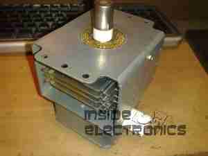
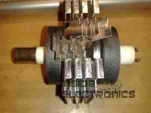
- Axial – These will most likely be permanent magnet toroids (similar to magnetron magnets), though an electromagnetic coil (possibly with adjustable or selectable field strength) could also be used. Thus, the North and South poles will be directed along the tube axis:
                        +--+      +--+      +--+      +--+
                      N |  | S  N |  | S  N |  | S  N |  | S
                        +--+      +--+      +--+      +--+
            ||======================================================||
            ||====. .========================================. .====||
                  |||   +--+      +--+      +--+      +--+   |_|
                  '|' N |  | S  N |  | S  N |  | S  N |  | S '|'
                        +--+      +--+      +--+      +--+
Other axial configurations with opposing poles or radially oriented poles may also be used or there may be a single long solenoid type of coil or cylindrical permanent magnet as for a two-frequency laser interferometer.
