Posted on Leave a comment

Stripboard Magic – A Call For Information

Some time ago I posted about an ancient piece of EDA software called Stripboard Magic, which was made by a small British company by the name of Ambyr. I have been hosting copies of this now long-dead software for some time, as it still seems to be in popular demand long after being abandoned by it’s creators. I have been contacted by a reader about the existence of Service Packs for this application, which neither of us have been able to locate.

From what I have been able to gather, Ambyr ceased trading around 1999-2000, after having sold the rights to distribute Stripboard Magic to Maplin Electronics. What I’m not certain of is the timeframe of these service packs appearing, or where they could originally be found, the Ambyr website apparently vanished about 6 months after Stripboard Magic was originally released, but they were presumably intended to make the application easier to use & less buggy.
Unfortunately the timeframe for the company’s existence was before the Wayback Machine started archiving the internet, and the only record they have of Ambyr is a domain holding page dating back to 2000.

If there are any readers who have copies of these service packs, or some information on where they can be found, or indeed any more information in general about this seemingly short-lived company, please drop a comment or E-Mail me directly through the Contact Page. Inquiring minds need to know 😉

73s, de 2E0GXE

Posted on 2 Comments

Maplin 600W “Modified Sine” Power Inverter

Maplin 600W Inverter

I’m no fan of power inverters. In my experience they’re horrifically inefficient, have power appetites that make engine starter motors look like electric toothbrushes & reduce the life expectancy of lead-acid batteries to no more than a few days.
However I have decided to do a little analysis on a cheapo “600W” model that Maplin Electronics sells.

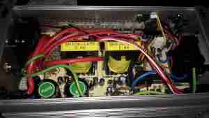
Cover Removed
Cover Removed

After a serious amount of metallic abuse, the bottom cover eventually came off. The sheet of steel used to close the bottom of the aluminium extrusion was wedged into place with what was probably a 10 ton hydraulic press.
As can be seen from the PCB, there’s no massive 50Hz power transformer, but a pair of high frequency switching transformers. Obviously this is to lighten the weight & the cost of the magnetics, but it does nothing for the quality of the AC output waveform.

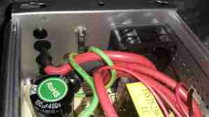
DC Input End
DC Input End

The 12v DC from the battery comes in on very heavy 8-gauge cables, this device is fused at 75A!

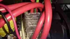
DC Fuses
DC Fuses

Here’s the fusing arrangement on the DC input stage, just 3 standard blade-type automotive fuses. Interestingly, these are very difficult to get at without a large hammer & some swearing, so I imagine if the user manages to blow these Maplin just expect the device to be thrown out.

Input DC-DC Switching MOSFETs

On the input side, the DC is switched into the pair of transformers to create a bipolar high voltage DC supply.

High Voltage Rectifiers

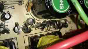
The large rectifier diodes on the outputs of the transformers feed into the 400v 100µF smoothing capacitors.
As mains AC is obviously a bipolar waveform, I’m guessing this is generating a ±150v DC supply.

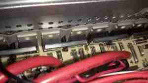
Output MOSFETs
Output MOSFETs

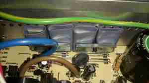
After the high voltage is rectified & smoothed, it’s switched through 4 more MOSFETs on the other side of the PCB to create the main AC output.

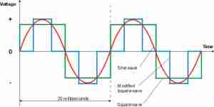
The label states this is a modified-sine output, so I’d expect something on the scope that looks like this:

Inverter Waveforms
Inverter Waveforms

Modified-sine doesn’t look as bad as just a pure square output, but I suspect it’s a little hard on inductive loads & rectifiers.

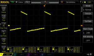
However, after connecting the scope, here’s the actual waveform:

Actual Waveform
Actual Waveform

It’s horrific. It’s not even symmetrical. There isn’t even a true “neutral” either. The same waveform (in antiphase) is on the other mains socket terminal. This gives an RMS output voltage of 284v. Needless to say I didn’t try it under load, as I don’t possess anything I don’t mind destroying. (This is when incandescent lamps are *really* useful. Bloody EU ;)).

About the only thing that it’s accurate at reproducing is the 50Hz output, which it does pretty damn well.

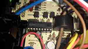
System Microcontroller

As is usual these days, the whole system is controlled via a microcontroller.

Posted on Leave a comment

Uniden UBC92XLT Teardown

One bit of my equipment that I’ve never looked into is my scanner, a handheld Uniden unit. I got this when Maplin Electronics had them on special offer a few years ago.

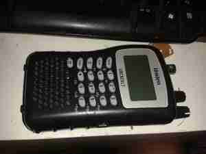
Uniden Scanner
Uniden Scanner

Here’s the scanner itself, roughly the same size as a usual HT.

Back Cover Removed
Back Cover Removed

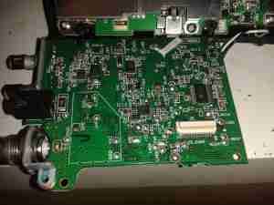
Here the back cover has been removed, and the main RF board is visible at the top of the stack. Unfortunately the shielding cans are soldered on this unit, so no looking under there 🙁
On the right hand side of the board next to the antenna input is the main RF filter network, and it’s associated switching. The RF front end is under the shield closest to the front edge.

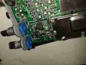
Controls & 3.3v Regulator

On the other side of the PCB is the Volume & Squelch potentiometers, along with a dedicated 3.3v switching supply. An NJM2360A High Precision DC/DC converter IC controls this one. A 3.3v test point is visible next to the regulator.

RF Board Reverse
RF Board Reverse

Here’s the backside of the RF board, some more interesting parts here. There’s a pair of NJM3404A Single Supply Dual Op-Amp ICs, and a TK10931V Dual AM/FM IF Discriminator IC. This is the one that does all the back-end radio functionality. The audio amplifier for the internal speaker & external headphone jack is also on this PCB, top left. A board-to-board interconnect links this radio board with the main control board underneath.

Control PCB Front
Control PCB Front

Here’s the front of the control PCB, nothing much to see here, just the LCD & membrane keypad contacts.

Control PCB Reverse
Control PCB Reverse

And here’s the reverse side of the control board. All the interesting bits are here. The main microcontroller is on the right, a Renesas M38D59GF, a fairly powerful MCU, with onboard LCD drive, A/D converter, serial interface, 60K of ROM & 2K of RAM. It’s 6.143MHz clock crystal is just below it.
The mating connector for the RF board is in the centre here.

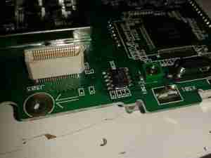
There is also a Microchip 24LC168 16KB I²C EEPROM next to the main microcontroller. This is probably for storing user settings, frequencies, etc.

EEPROM
EEPROM

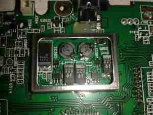
The rest of this board is dedicated to battery charging and power supply, in the centre is a dual switching controller, I can’t figure out the numbers on the tiny SOT23 components in here, but this is dealing with the DC 6v input & to the left of that is the circuitry for charging the NiMH cells included with the scanner.

PSU
PSU

The last bit of this PCB is a BU2092FV Serial In / Parallel Out 4 channel driver. Not sure what this one is doing, it might be doing some signal multiplexing for the RF board interface. Unfortunately the tracks from this IC are routed on the inner layers of the board so they can’t be traced out.

Posted on Leave a comment

Brother P-Touch 80 Label Maker

Touchpad
Touchpad

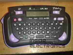
Here is a label maker, bought on offer at Maplin Electronics. Full Qwerty keyboard with 1 line dot matrix LCD display visible here. Power is 4 AAA cells or a 6v DC Adaptor.

Rear
Rear

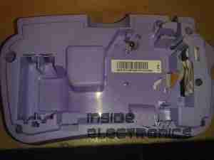
Rear cover removed. Battery compartment is on the left hand side, space for the tape cartridge on the right. Ribbon cable leading to the thermal print head is on the far right, with rubber tape drive roller.

PCB
PCB

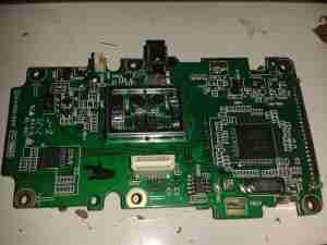
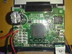
PCB under the top cover with the main CPU, a MN101C77CBM from Panasonic. This CPU features 48K Mask ROM & 3K of RAM. Max clock frequency is 20MHz. 32kHz clock crystal visible underneath a Rohm BA6220 Electronic speed controller IC.
This is used to drive the printer motor at a constant accurate speed, to feed the tape past the thermal head. Miniature potentiometer adjusts speed.
Ribbon cable at the bottom of the board connects to the print head, various wiring at the left connects to the battery & DC Jack.

Printer Drive
Printer Drive

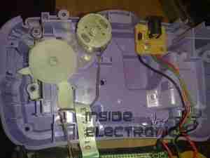
Printer drive mechanism. Small DC motor drives the pinch roller though a gear train. DC Jack & reverse polarity protection diode is on the right.
This unit uses a centre negative DC jack, which is unusual.

Cartridge
Cartridge

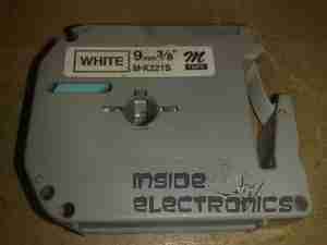
Thermal tape cartridge, black text on white background.