Posted on Leave a comment

UM25C USB Power Meter

UM25C USB Power Meter

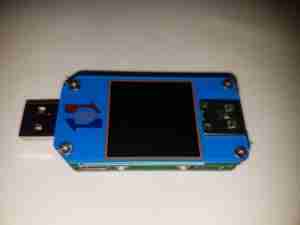
Here’s a nice little feature-packed USB power meter, the UM25C. This unit has USB-C along with the usual USB type A connectors, along with a bluetooth radio for remote monitoring of stats via a Windows or Android app. Construction is nice, it’s a stack of two PCBs, and polycarbonate cover plates, secured together with brass posts & screws.
Back Cover
Back Cover

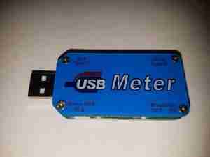
The back cover has the legend for all the side connectors, along with the logo.
USB Micro Input
USB Micro Input

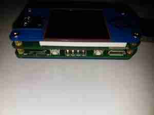
Down the sides are the user interface buttons, and here the Micro-B input connector. The 4-pin header is visible here that takes serial data down to the bluetooth section.
USB-C Connectors
USB-C Connectors

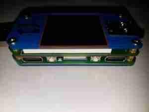
The other side has the remaining pair of buttons, and the USB-C I/O. I don’t yet own anything USB-C based, but this is good future proofing.
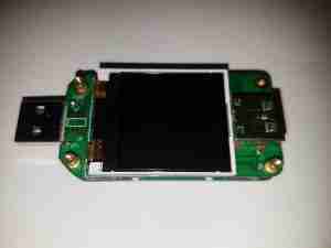
LCD Display
LCD Display

Removing the top plastic cover plate reveals the small 1″ TFT LCD module. This will be hot-bar soldered underneath the screen. There’s an unused footprint next to the USB input connector, judging by the pin layout it’s probably for a I²C EEPROM.
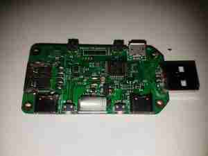
Main Board Components

The underside of the top PCB has all the main components. The brains of the operation is a ST STM8S005C6T6 microcontroller. It’s at the basic end of the STM range, with a 16MHz clock, 32K flash, EEPROM, 10-bit ADC, SPI, UART & I²C. The main 0.010Ω current shunt is placed at the top left of the board in the negative rail. A couple of SOT-23 components in the centre of the board, I haven’t been able to identify properly, but I think they may be MOSFETs. The large electrolytic filter capacitor has a slot routed into the PCB to allow it to be laid flat. Providing the main power rail is a SOT-89 M5333B 3.3v LDO regulator.
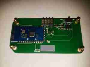
Bluetooth Radio
Bluetooth Radio

The bottom board contains the bluetooth radio module, this is a BK3231 Bluetooth HID SoC. The only profile advertised by this unit is a serial port. There’s a local 3.3v LDO regulator & support components, along with an indicator LED.
Posted on Leave a comment

Sony Xperia T Teardown

Back Cover Removed
Back Cover Removed

Since this phone has been in my drawer for some time, I figured it was time for a teardown. (It’s never going to see any more use).
The back cover on these phones is easily removed, as it’s just clipped on.

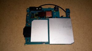
Motherboard
Motherboard

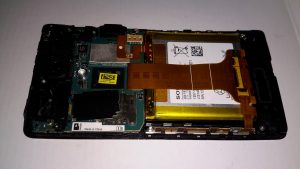
Once the back cover is removed, the Li-Polymer cell is exposed, along with the logic board. Pretty much all of the PCB is under RF shields.

Motherboard Removed
Motherboard Removed
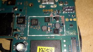
Battery Management
Battery Management

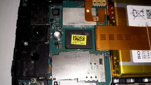
Under the small RF can on the back of the board is the battery management circuitry & the charger. There’s an extra connection to the cell for temperature monitoring. Just under that circuitry is the eMMC flash storage.
Just to the left of the battery circuit is the NFC transceiver IC, from NXP.

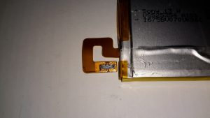
Battery Flex
Battery Flex

The cell is connected to the main board with a FFC, with a very small SMT connector, although not as small as the more modern Xperia series phones.

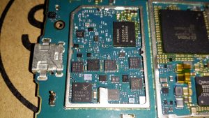
RF Section
RF Section

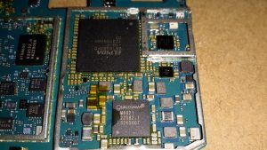
The other side of the mainboard holds the large RF transceiver section, with a Qualcomm RTR8600 multiband transceiver IC. In the bottom corner is a Skyworks SKY77351-32 Quad-band power amplifier IC, along with 3 other power amplifier ICs, also from Skyworks.

Gyro & Audio Codec
Gyro & Audio Codec

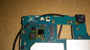
The top corner of the board holds the various sensors, including an Invensense MPU-3050 3-axis gyro. To the right of that is the Audio Codec, a WCD9310 from Qualcomm.

Logic & CPU Section
Logic & CPU Section

Everything is controlled from the last section on the board, with the main CPU & RAM in a PoP (Package-On-Package) configuration. Under the main CPU is the main power management IC, also from Qualcomm. No datasheet for this one unfortunately, but it gives it’s purpose away by being surrounded by large inductors & capacitors.

Posted on Leave a comment

Domain Moved!

I finally managed to get the domain for the website switched over to the new!

This will complete the rebranding operation, all seems to have gone well & the old domain is still active via a 301 permanent redirect.

I will be monitoring the logs in the meantime for any errors that pop up – WordPress is sometimes rather funny about being moved.

73s for now!

Posted on Leave a comment

Pilot LPG Monitoring System

Pilot Gas Monitor
Pilot Gas Monitor

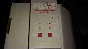
In my mind, the most dangerous thing onboard any boat is the LPG system, as the gas is heavier than air, any leaks tend to collect in the bilges, just waiting for an ignition source. To mitigate this possibility, we’re fitting a gas monitoring system that will sound an alarm & cut off the supply in case of a leak.

Monitor Unit
Monitor Unit

Here’s the monitor itself, the two sensor model. It’s nice & compact, and the alarm is loud enough to wake the dead.

Control Board
Control Board

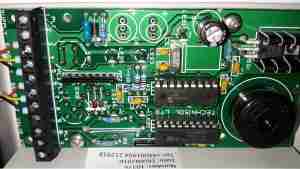
Not much inside in the way of circuitry, the brains of the operation is a Microchip PIC16F716 8-bit microcontroller with an onboard A/D converter (needed to interface with the sensors), running at 4MHz. The solenoid valve is driven with a ULN2803 Darlington transistor array.
The alarm Piezo sounder can be seen to the right of the ICs, above that is a simple LM7805 linear regulator providing power to the electronics.

Remote Sensor
Remote Sensor

The pair of remote sensors come with 3.5m of cable, a good thing since the mounting points for these are going to be rather far from the main unit in our installation.

Sensor Element
Sensor Element

The sensor itself is a SP-15A Tin Oxide semiconductor type, most sensitive to butane & propane. Unlike the Chinese El-Cheapo versions on eBay, these are high quality sensors. After whiffing some gas from a lighter at one of the sensors, the alarm triggered instantly & tripped the solenoid off.

Solenoid Valve
Solenoid Valve

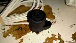
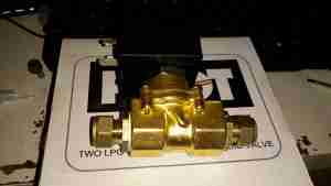
The solenoid valve goes into the gas supply line after the bottle regulator, in this case I’ve already fitted the adaptors to take the 10mm gas line to the 1/2″ BSP threads on the valve itself. This brass lump is a bit heavy, so support will be needed to prevent vibration compromising the gas line.

Posted on 1 Comment

IC Decap: ITE IT8712F Super I/O Controller

IT8712F Package
IT8712F Package

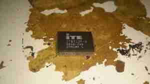
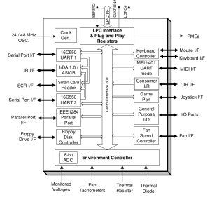
These chips are used on PC motherboards, to control many of the legacy peripherals & things such as temperature monitoring & fan speed control.

Here’s the block diagram from the datasheet to show all the features, this IC handles many things on a modern motherboard!

Block Diagram
Block Diagram
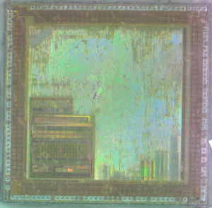
IT8712F Die
IT8712F Die
Posted on Leave a comment

Marine Potable Water Management System

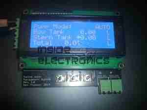
LCD Panel
LCD Panel

Having two separate water tanks on nb Tanya Louise, with individual pumps, meant that monitoring water levels in tanks & keeping them topped up without emptying & having to reprime pumps every time was a hassle.
To this end I have designed & built this device, to monitor water usage from the individual tanks & automatically switch over when the tank in use nears empty, alerting the user in the process so the empty tanks can be refilled.

Based around an ATMega328, the unit reads a pair of sensors, fitted into the suction line of each pump from the tanks. The calculated flow is displayed on the 20×4 LCD, & logged to EEPROM, in case of power failure.

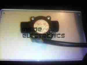
Water Flow Sensor
Water Flow Sensor

When the tank in use reaches a preset number of litres flowed, (currently hardcoded, but user input will be implemented soon), the pump is disabled & the other tank pump is enabled. This is also indicated on the display by the arrow to the left of the flow register. Tank switching is alerted by the built in beeper.
It is also possible to manually select a tank to use, & disable automatic operation.
Resetting the individual tank registers is done by a pair of pushbuttons, the total flow register is non-resettable, unless a hard reset is performed to clear the onboard EEPROM.

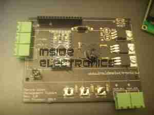
Main PCB
Main PCB

View of the main PCB is above, with the central Arduino Pro Mini module hosting the backend code. 12-24v power input, sensor input & 5v sensor power output is on the connectors on the left, while the pair of pump outputs is on the bottom right, switched by a pair of IRFZ44N logic-level MOSFETS. Onboard 5v power for the logic is provided by the LM7805 top right.

Code & PCB design is still under development, but I will most likely post the design files & Arduino sketch once some more polishing has been done.

Posted on Leave a comment

Site Hosting

Original Rack
Original Rack

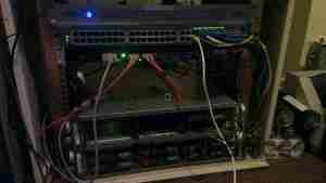
There have been quite a few updates to the hosting solution for this site, which is hosted locally in my house, from the above setup, in a small comms rack, to a new 22U half rack, with some hardware upgrades to come.

Core Switch Disconnected

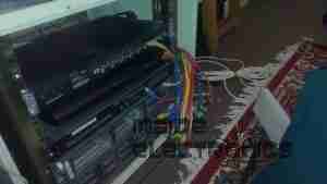
Core switch here has been removed, with the rest of the core network equipment. The site was kept online by a direct connection into the gateway to the intertubes.

Switching Gear Installed

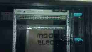
New 22U rack, with the core switch, FC switch & management & monitoring server installed.

Router Going In
Router Going In

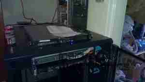
As I had no rack rails to start with, the servers were placed on the top of the rack to start off, here is the Dell PowerEdge 860 pfSense core router installed, with the initial switch wiring to get the internal core network back online. This machine load balances two connections for an aggregated bandwidth of 140MB/s downstream & 15MB/s upstream.
The tower server behind is the NAS unit that runs the backups of the main & auxiliary webservers.

Almost Done
Almost Done

Still with no rack kits, all the servers are placed on top of the rack, before final installation. This allows running of the network before the rest of the equipment was installed.

The main server & aux server are HP ProLiant DL380 G3 servers, with redundant network connections.

Still to arrive are the final rack kits for the servers & a set of HP BL20p Blade servers, which will be running the sites in the future.

Stay tuned for more updates as they happen!

Posted on 2 Comments

Epson Ink Cartridge Resetter

Interface
Interface

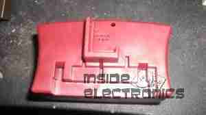
This is a device designed to reset Epson brand ink cartridges that are reportedly out of ink, so they again report full to the printer Here is the front of the unit, with the guide for attaching to a cartridge.

PCB Back
PCB Back

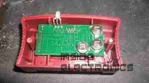
Back of the device removed. 3 button cells provide power to the PCB. Indicator LED sticks out of the top of the device for reset confirmation.
Row of pads on far left edge of the PCB are presumably a programming header for the uC on the other side of the board.

PCB Front
PCB Front

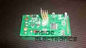
Here is the  front of the PCB, main feature being the grid of pogo pins to connect to the cartridge chip. IC on lower right of that is a MSP430F2131 uController, a Texas Instruments part.
The IC directly to the left of the pogo pin bed is a voltage regulator, to step down the ~4.5v of the batteries down to the ~3.3v that the uC requires.