Posted on Leave a comment

HP Photosmart 375

Top
Top

This is a HP PhotoSmart 375 portable photo printer. With built in card reader, screen & PictBridge.
Top of the printer showing the UI Buttons & Screen.
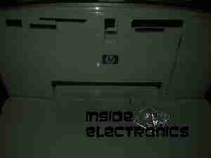
Front
Front

Front of the unit, card reader slots at the top, Pictbridge USB connector at top left. Paper out slot at bottom. Cartridge door is on the right.
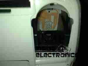
Cartridge Door
Cartridge Door

Here the cartridge door is open. Takes HP 95 Tri-Colour Inkjet Cartridge.
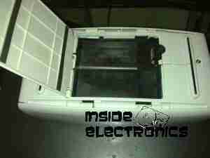
Battery Compartment
Battery Compartment

Battery compartment on the bottom of the unit. A Li-Ion battery pack can be installed here for mobile photo printing.
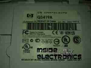
Bottom Label
Bottom Label

Specifications label.

USB + Power
USB + Power

Power adaptor & USB connection for PC use.

Paper Tray
Paper Tray

Rear door opened. Showing the paper feed tray.
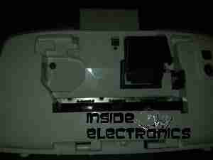
Paper Feeder
Paper Feeder

Rear door has been removed in this shot. Paper feed roller & platen roller can be seen here.
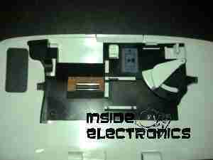
Rear Cover Paper Feeder

Paper holder attached to rear door.

Top Cover
Top Cover

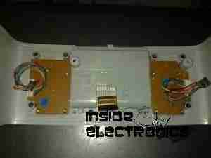
Bottom of the top cover, with connections for the buttons & LCD panel.
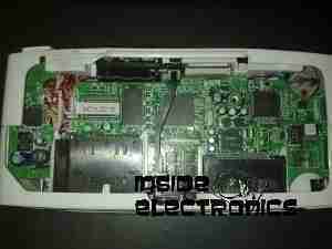
Main PCB
Main PCB

This is the main PCB of the unit. Controls all aspects of the printer. CPU in center, card reader sockets are along bottom edge. various support circuitry surrounds the CPU.
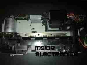
Rear
Rear

Rear shell has been removed here. Showing the main frame & the carriage drive motor on the left.
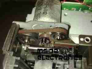
Carriage Drive
Carriage Drive

Closeup of the carriage drive motor & timing belt system. All the motors in this printer are DC servo motors, not steppers.
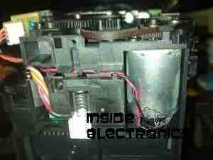
Main Drive Motor
Main Drive Motor

Main drive motor, feeds paper, drives rollers, operates cleaning mechanism for the inkjets.
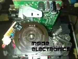
Shaft Encoder
Shaft Encoder

Mainshaft encoder. Main drive motor is bottom right hand side with timing belt drive.
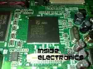
CPU
CPU

Closeup of the CPU. This is a Phillips ARM chip, unknown spec.
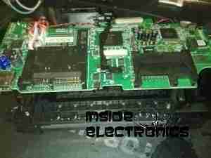
Card Reader Sockets
Card Reader Sockets

Detail of the card reader sockets, this unit takes all current types of Flash memory card.
HP 95 Tri-color Inkjet Print Cartridge
Posted on 1 Comment

ICL Barcode Scanner

Top
Top

An ICL barcode scanner from the 80s is shown here. This is the top of the unit with cover on.

Cover Removed
Cover Removed

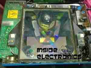
Plastic cover removed from the unit showing internal components. Main PSU on left, scan assembly in center. Laser PSU & Cooling fan on right. Laser tube at top.

Scan Motor
Scan Motor

Closeup of laser scan motor. This unit scans the laser beam rapidly across the glass plate to read the barcode.

Controller PCB
Controller PCB

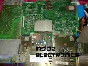
View of the bottom of the unit, showing the controller PCB in the centre.

Scan Motor Driver
Scan Motor Driver

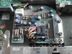
The 3-phase motor driver circuit for the scan motor. 15v DC powered.

Laser Unit
Laser Unit

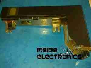
This is the laser unit disconnected from the back of the scanner. HT PSU is on right hand side, beam emerges from optics on left.

Laser Unit Label
Laser Unit Label

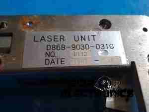
This unit is date stamped 1987. The oldest laser unit i own.

Tube PSU
Tube PSU

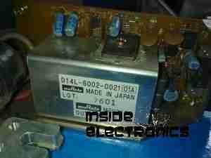
Laser tube power supply. Input voltage: 24v DC. Output: 1.8kV 4mA.

Laser PSU Board
Laser PSU Board

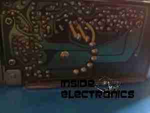
Rear of HT PSU. Obviously the factory made a mistake or two 🙂

Laser Tube Mounting
Laser Tube Mounting

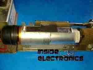
Top cover removed from the laser unit here shows the 1mW He-Ne tube. Manufactured by Aerotech.

Tube Label
AeroTech He-Ne Tube

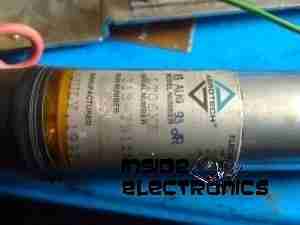
Tube label. Manufactured July 1993. Model LT06XR.

Plasma
Plasma

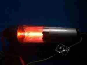
Here the tube has been removed from it’s mount to show the bore down the centre while energized.

OC Mirror
OC Mirror

OC end of the tube shown here lasing.

Beam
Beam

Beam output from the optics on the laser unit.

Tube Optics
Tube Optics

Optics built into the laser unit. Simple turning mirror on adjustable mount & collimating lens assembly.

Scan Lines
Scan Lines

Kind of hard to see but the unit is running here & projecting the scan lines on the top glass.

Laser Tube Mounting
Laser Tube Mounting

Laser tube mounting. A combo of spring clips & hot glue hold this He-Ne tube in place

Posted on Leave a comment

Hair Dryer

Housing
Housing

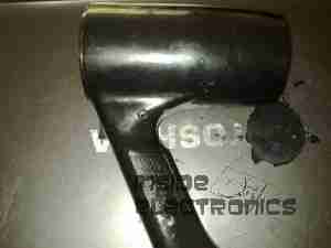
This is a 1500W hairdryer, death caused by thermal switch failure.

Switch
Switch

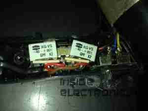
This is the switch unit. Attached are two suppression capacitors & a blocking diode. Cold switch is on right.

Heating Element
Heating Element

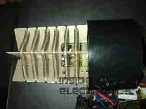
Heating element unit removed from housing. Coils of Nichrome wire heat the air passing through the dryer. Fan unit is on right.

Thermal Switch
Thermal Switch

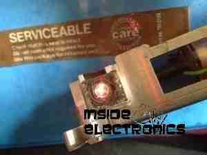
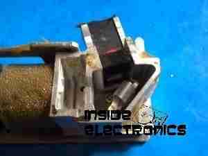
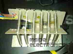
Other side of the heating element unit, here can be seen the thermal switch behind the element winding. (Black square object).

Fan Motor
Fan Motor

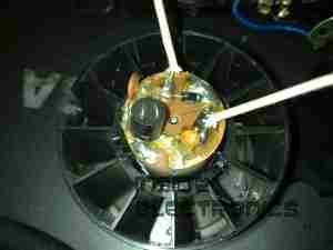
The fan motor in this dryer is a low voltage DC unit, powered through a resistor formed by part of the heating element to drop the voltage to around 12-24v. Mounted on the back of the motor here is a rectifier assembly. Guide vanes are visible around the motor, to straighten the airflow from the fan blades.

Fan
Fan

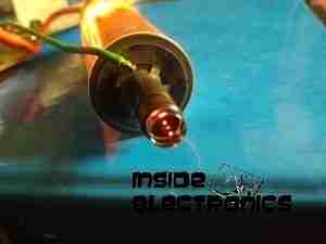
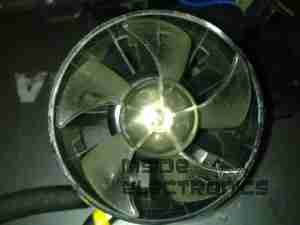
5-blade fan forces air through the element at high speed. Designed to rotate at around 13,000RPM.

Posted on Leave a comment

Western Digital 160GB 2.5″ HDD

Top Of Drive With Label
Top

This is a Western Digital drive recently removed from my laptop when it died of a severe head crash.
Top of drive can be seen here.

Top Removed From Drive
Top Removed

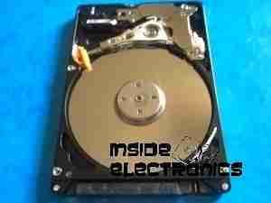
Here the cover has been removed from the drive, showing the platter, head arm & magnet. Yellow piece top left is head parking ramp.

Head Arm of Drive
Head Arm

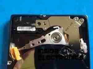
The head assembly of the drive is shown here. The head itself is on the left hand end of the arm in the plastic parking ramp. The other end of the arm holds the voice coil part of the head motor, surrounded by the magnet.

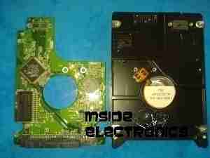
Bottom Of Drive with PCB

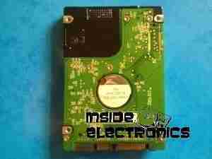
Bottom of drive, with controller PCB. SATA interface socket at bottom.

PCB removed from bottom of drive. Spindle motor connections & connections to the head unit can be seen on the bottom of the drive unit.

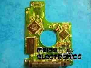
Controller PCB. Supports the cache, interface & motor controller ICs.

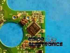
Closeup of the motor driver IC, this controls the speed of the spindle motor precisely to 5,400RPM. Also controls the voice coil motor controlling the position of the head arm on the platters.

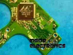
Interface IC closeup. This IC receives signals from the head assembly & processes them for transmission to the SATA bus. Also holds drive firmware, controls the Motor driver IC & all other functions of the drive.

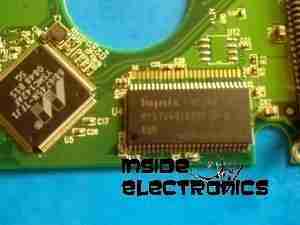
Cache Memory IC.