Since the engine & hydrostatic transmission were installed in the boat a few years back, the hydraulic oil cooler has been in the same fresh water circuit as the engine’s water cooling system, however this has been causing some heat issues with the engine & hydraulic system under a heavy load, such as when I’m using the onboard generator to run the welding gear. The hydraulic oil temp would rise to over 80°C during the course of a long day’s cruising – such temperatures will degrade the oil very quickly, and in turn will cause premature wear of the very expensive hydraulic pumps. (Not to mention increasing the requirement for hydraulic oil changes, which are very expensive). The engine oil has been cooled by a standard automotive oil radiator, with air forced over the matrix by two large fans. This is also pretty inefficient, so another cooler will be added to replace the automotive one.
This cooling requirement is caused by the inefficiency of hydraulic systems – a simple variable displacement piston pump driving a bent-axis piston motor has an overall efficiency of roughly 80%. Given our engine’s max power of 76HP (56.7kW), this gives an energy loss of 15.2HP (11.33kW) at maximum power. This extra heat overloaded the skin tank, resulting in a cooling system that didn’t really work all too well once the engine was hot.
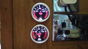
To solve this issue, we’ve decided to run a raw water circuit using the canal to remove the waste heat from the hydraulic system & engine oil, putting less of a heat load on the skin tank to bring the temperatures down to something reasonable. The image above show the system at running temperature after I installed the monitoring instruments. The top gauge is measuring engine oil temperature, at the point where it’s being fed to the bearings. The bottom one is measuring hydraulic oil temperature.
The engine oil temperature does have to be higher than any other cooling circuit on board, to boil off any condensate from the cylinders. Overcooling the oil in the sump will eventually cause sludging as the oil tries to absorb the resulting water. I’m aiming for a system temperature in the engine oil circuit of 95°C-120°C when the engine is under load & at operating temperature.
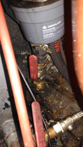
Water from the canal is drawn from a skin fitting installed at the last drydock visit, pulling water through a strainer to remove all the large bits of muck. The large slotted screen on the suction skin fitting keeps larger objects out of the intake.
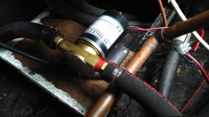
A flexible impeller pump provides the power to move water through the system, in this case about 25L/Min. This pump is a cheap copy of a Jabsco pump from eBay. So far it’s been pretty reliable.
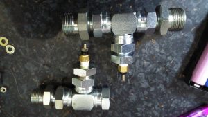
The temperature senders are standard automotive parts, and some adaptors were required to graft them into the oil lines of both systems. The senser’s 1/8″ NPT threads are here fitted into 1/2″ BSP hydraulic fittings.
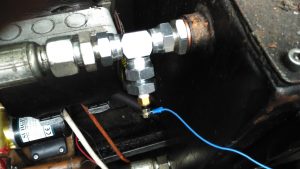
Here’s the hydraulic oil sender installed in the drain line from the main propulsion pump, this should give me a pretty good idea of the temperature of the components in the system, the sender is earthed through the steel hydraulic oil tank.
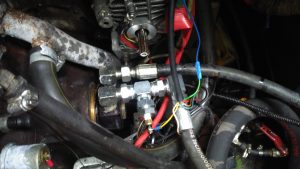
The oil temperature sender is installed in the return line to the engine from the heat exchanger. This is measuring the oil temperature the bearings in the engine are being fed with.
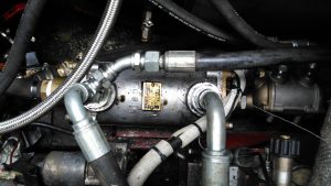
The stack of heat exchangers is located on the starboard side of the engine bay, the large one here is cooling the hydraulic oil, the auxiliary pump is continually circulating the oil from the tank through this, then into the return filter on the top of the tank.
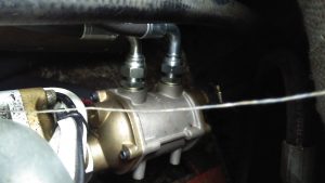
The engine oil is fed through this much smaller heat exchanger mounted on the back of the large hydraulic cooler, the last in the circuit before the water is discharged back overboard through a skin fitting.
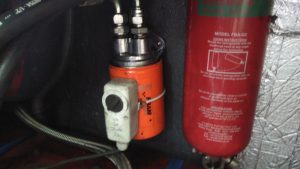
As we’ve got the diverter block on the side of the engine where the oil filter should be, a remote oil filter is fitted above the fuel tank. The thermostat strapped on operates the main engine bay ventilation fans, switching them on once the engine oil reaches 60°C.
