He-Ne Laser Safety

As with *any* laser, proper precautions must be taken to avoid any possibility of damage to vision. The types of He-Ne lasers mostly dealt with in this document are rated Class II, IIIa, or the low end of IIIb (see the section: Laser Safety Classifications. For most of these, common sense (don’t stare into the beam) and fairly basic precautions suffice since the reflected or scattered light will not cause instantaneous injury and is not a fire hazard.

However, unlike those for laser diodes, He-Ne power supplies utilize high voltage (several kV) and some designs may be potentially lethal. This is particularly true of AC line powered units since the power transformer may be capable of much more current than is actually required by the He-Ne laser tube – especially if it is home built using the transformer from some other piece of equipment (like an old tube type console TV or that utility pole transformer you found along the curb) which may have a much higher current rating.

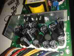
The high quality capacitors in a typical power supply will hold enough charge to wake you up – for quite a while even after the supply has been switched off and unplugged. Depending on design, there may be up to 10 to 15 kV or more (but on very small capacitors) if the power supply was operated without a He-Ne tube attached or it did not start for some reason. There will likely be a lower voltage – perhaps 1 to 3 kV – on somewhat larger capacitors. Unless significantly oversized, the amount of stored energy isn’t likely to be enough to be lethal but it can still be quite a jolt. The He-Ne tube itself also acts as a small HV capacitor so even touching it should it become disconnected from the power supply may give you a tingle. This probably won’t really hurt you physically but your ego may be bruised if you then drop the tube and it then shatters on the floor!

However, should you be dealing with a much larger He-Ne laser, its power supply is going to be correspondingly more dangerous as well. For example, a 35 mW He-Ne tube typically requires about 8 mA at 5 to 6 kV. That current may not sound like much but the power supply is likely capable of providing much more if you are the destination instead of the laser head (especially if it is a home-made unit using grossly oversized parts)! It doesn’t take much more under the wrong conditions to kill.

After powering off, use a well insulated 1M resistor made from a string of ten 100K, 2 W metal film resistors in a glass or plastic tube to drain the charge – and confirm with a voltmeter before touching anything. (Don’t use carbon resistors as I have seen them behave funny around high voltages. And, don’t use the old screwdriver trick – shorting the output of the power supply directly to ground – as this may damage it internally.)

And only change electrical connections or plug/unplug connectors with power OFF, being aware of the potential for stored charge. In particular, the aluminium cylinder of some HeNe laser heads is the negative return for the tube current via a spring contact inside the rear end-cap. So, pulling off the rear end-cap while the laser is powered will likely make YOU the negative return instead! You will probably then bounce off the ceiling while the laser bounces off the floor, which can easily ruin your entire day in more ways than one. πŸ™ πŸ™‚ This connection scheme is known to be true for most JDS Uniphase and many Melles Griot laser heads, but may apply to others as well.

Now, for some first-hand experience:

(From: Doug (dulmage@skypoint.com).)

Well, here’s where I embarrass myself, but hopefully save a life…

I’ve worked on medium and large frame lasers since about 1980 (Spectra-Physics 168’s, 171’s, Innova 90’s, 100’s and 200’s – high voltage, high current, no line isolation, multi-kV igniters, etc.). Never in all that time did I ever get hurt other than getting a few retinal burns (that’s bad enough, but at least I never fell across a tube or igniter at startup). Anyway, the one laser that almost did kill me was also the smallest that I ever worked on.

I was doing some testing of AO devices along with some small cylindrical HeNe tubes from Siemens. These little coax tubes had clips for attaching the anode and cathode connections. Well, I was going through a few boxes of these things a day doing various tests. Just slap them on the bench, fire them up, discharge the supplies and then disconnect and try another one. They ran off a 9 VDC power supply.

At the end of one long day, I called it quits early and just shut the laser supply off and left the tube in place as I was just going to put on a new tube in the morning. That next morning, I came and incorrectly assumed that the power supply would have discharged on it own overnight. So, with each hand I stupidly grab one clip each on the laser to disconnect it. YeeHaaaaaaaaa!!!!. I felt like I had been hid across my temples with a two by four. It felt like I swallowed my tongue and then I kind of blacked out. One of the guys came and helped me up, but I was weak in the knees, and very disoriented.

I stumbled around for about 15 minutes and then out of nowhere it was just like I got another shock! This cycle of stuff went on for about 3 hours, then stopped once I got to the hospital. I can’t even remember what they did to me there. Anyway, how embarrassing to almost get killed by a HeNe laser after all that other high power stuff that I did. I think that’s called ‘irony’.

Comments on HeNe Laser Safety Issues

(Portions from: Robert Savas (jondrew@mail.ao.net).)

A 10 mw HeNe laser certainly presents an eye hazard.

According to American National Standard, ANSI Z136.1-1993, table 4 Simplified Method for Selecting Laser Eye Protection for Intrabeam Viewing, protective eyewear with an attenuation factor of 10 (Optical Density 1) is required for a HeNe with a 10 milliwatt output. This assumes an exposure duration of 0.25 to 10 seconds, the time in which they eye would blink or change viewing direction due the uncomfortable illumination level of the laser. Eyeware with an attenuation factor of 10 is roughly comparable to a good pair of sunglasses (this is NOT intended as a rigorous safety analysis, and I take no responsibility for anyone foolish enough to stare at a laser beam under any circumstances). This calculation also assumes the entire 10 milliwatts are contained in a beam small enough to enter a 7 millimeter aperture (the pupil of the eye). Beyond a few meters the beam has spread out enough so that only a small fraction of the total optical power could possible enter the eye.

Laser Safety Classifications

A Smorgasbord of Acronyms

There are ANSI, OSHA, FDA (CDRH), NRPB, and military standards. The CDRH (Center for Devices and Radiological Health is part of the Food and Drug Administration and is the most relevant regulatory organization in the USA for commercial and scientific lasers. The complete CDRH document may be found at: Performance Standard for Light Emitting Products.

As of Summer 2007, there is an updated “ANSI Z136.1 (2007) Safe Use of Lasers” which among other things substitutes Class 3R for Class 3A, add Classes 1M and 2M, changes some of the control measures and terminology, and more. Nothing earth shattering though. I have not yet seen a full copy. However, there is a summary article in the June 2007 Photonics Spectra magazine. And a narrated slide show of the changes can be found in the Laser Institute of America ANSI Z.136.1 Presentation. However, without details or access to the full document, it’s an excellent cure for insomnia at best. πŸ™‚ Also see: Wikipedia: Laser Safety, which includes many references and some links.

The best discussion of the various classifications, plus general treatment of the topic, is a book by Sliney and Wolbarsht, “Safety with Lasers and Other Optical Sources”, Plenum Press, New York. While they will agree with each other in most respects, some differences will result in a particular laser changing classes depending on which standard is used. The major criteria are summarized below.

Note: I may use Class 1 and Class I, Class 2 and Class II, Class 3 and Class III, and Class 4 and Class IV interchangeably. They are equivalent.

The following is based on material from the University of Waterloo – Laser Safety Manual.

All lasers are classified by the manufacturer and labelled with the appropriate warning labels. Any modification of an existing laser or an unclassified laser must be classified by the Laser Safety Officer prior to use. The following criteria are used to classify lasers:

  1. Wavelength. If the laser is designed to emit multiple wavelengths the classification is based on the most hazardous wavelength.
  2. For continuous wave (CW) or repetitively pulsed lasers the average power output (Watts) and limiting exposure time inherent in the design are considered.
  3. For pulsed lasers the total energy per pulse (joule), pulse duration, pulse repetition frequency and emergent beam radiant exposure are considered.

Lasers are generally classified and controlled according to the following criteria:

  • Class I lasers – Lasers that are not hazardous for continuous viewing or are designed in such a way that prevent human access to laser radiation. These consist of low power lasers or higher power embedded lasers (e.g., laser printer or DVD burner).
  • Class II visible lasers (400 to 700 nm) – Lasers emitting visible light which because of normal human aversion responses, do not normally present a hazard, but would if viewed directly for extended periods of time. This is like many conventional high intensity light sources.
  • Class IIa visible lasers (400 to 700 nm) – Lasers emitting visible light not intended for viewing, and under normal operating conditions would not produce a injury to the eye if viewed directly for less than 1,000 seconds (e.g., bar code scanners).
  • Class IIIa lasers – Lasers that normally would not cause injury to the eye if viewed momentarily but would present a hazard if viewed using collecting optics such as a magnifier or telescope).
  • Class IIIb lasers – Lasers that present an eye and skin hazard if viewed directly. This includes both intrabeam viewing and specular reflections. Class IIIb lasers do not produce a hazardous diffuse reflection except when viewed at close proximity.
  • Class IV lasers – Lasers that present an eye hazard from direct, specular and diffuse reflections. In addition such lasers may be fire hazards and produce skin burns.

Here is another description, paraphrased from the CORD course: “Intro to Lasers”. (Cord Communications. Lasers.) It relates the laser classifications to common laser types and power levels:

  • Class I – EXEMPT LASERS, considered ‘safe’ for intrabeam viewing. Visible beam.Maximum power less than 0.4 uW for long term exposure (greater than 10,000 seconds). Looking at a Class I laser will not cause eye damage even where the entire beam enters the eye and it is being stared at continuously.A laser may also be labeled as Class I if it is entirely enclosed and not accessible without disassembly using tools. Thus, a DVD burner with a 150 mW laser diode (normally a Class IIIB laser) would still be considered Class I.
  • Class II – LOW-POWERED VISIBLE (CW) OR HIGH PRF LASERS, won’t damage your eye if viewed momentarily. Visible beam.Maximum power less than 1 mW for HeNe laser.
  • Class IIIa – MEDIUM POWER LASERS, focused beam can injure the eye.HeNe laser power 1.0 to 5.0 mW.
  • Class IIIb – MEDIUM POWER LASERS, diffuse reflection is not hazardous, doesn’t present a fire hazard.Visible Argon laser power 5.0 mW to 500 mW.
  • Class IV – HIGH POWER LASERS, diffuse reflection is hazardous and/or a fire hazard.

The classifications depend on the wavelength of the light as well and as noted, there may be additional considerations for each class depending on which agency is making the rules. For example, the NRPB (British) adds a requirement for Class IIIa that the power density for a visible laser not exceed 25 W/m2 which would thus bump some laser pointers with tightly focused beams from Class IIIa to Class IIIb. For more information on laser pointer safety and the NRPB classifications, see the NRPB Laser Pointer Article.

In the US, start with the Center for Devices and Radiological Health (CDRH), part of the Food and Drug Administration (FDA). See the section: Regulations for Manufacturers of Lasers and Laser Based Equipment for more info on how to find the relevant guidance documents.

For additional information on laser safety and laser safety classifications, see the section: Laser Safety Sites (May Also Include Other Laser Information).

Here is a table of the CDRH classification and labeling requirements for commercial laser products:

  Class   Max Power (mW)       Logotype             Warning Label Text
 -----------------------------------------------------------------------------
    I       <,= 0.39         None Required          None Required

   IIa    > 0.39 to 1.0      None Required          None Required
                         (Exposures < 1,000 s)

   II        <,= 1              CAUTION             Laser Radiation - Do not
                                                     stare into beam

  IIIa       <,= 5              CAUTION             Laser Radiation - Do Not
                         (Irradiance < 2.5 mW/cm2)    Stare into Beam or
                                                     View Directly with
                                                     Optical Instruments

                                CAUTION             Laser Radiation - Avoid
                        (Irradiance >,= 2.5 mW/cm2)  Direct Eye Exposure

  IIIb      <,= 500             DANGER              Laser Radiation - Avoid
                                                     Direct Exposure to Beam

   IV        > 500              DANGER              Laser Radiation - Avoid
                                                     Eye or Skin Exposure to
                                                     Beam

Here are some excerpts from the Center for Devices and Radiological Health (CDRH) regulation 21 CFR 1040.10 and 21 CFR 1040.11, the standard classification for lasers are as follows with some additional comments by Wes Ellison (erl@sunflower.com):

  • Class I laser productsNo known biological hazard. The light is shielded from any possible viewing by a person and the laser system is interlocked to prevent the laser from being on when exposed. (large laser printers such as the DEC LPS-40 had a 10 mW HeNe laser driving it which is a Class IIIb laser, but the printer is interlocked so as to prevent any contact with the exposed laser beam, hence the device produces no known biological hazard, even though the actual laser is Class IIIb. This would also apply to CD/DVD/Blu-ray players and recorders (which might have Class IIIb laser diodes of 100 mW or more) and small laser, as they are Class I devices).
  • Class II laser productsPower up to 1 milliwatt. These lasers are not considered an optically dangerous device as the eye reflex will prevent any occular damage. (I.e., when the eye is hit with a bright light, the eye lid will automatically blink or the person will turn their head so as to remove the bright light. This is called the reflex action or time. Class II lasers won’t cause eye damage in this time period. Still, one wouldn’t want to look at it for an extended period of time.) Caution labels (yellow) should be placed on the laser equipment. No known skin exposure hazard exist and no fire hazard exist.
  • Class IIIa laser productsPower output between 1 milliwatt and 5 milliwatt. These lasers can produce spot blindness under the right conditions and other possible eye injuries. Products that have a Class IIIa laser should have a laser emission indicator to tell when the laser is in operation. They should also have a Danger label and output aperture label attached to the laser and/or equipment. A key operated power switch SHOULD be used to prevent unauthorized use. No known skin hazard of fire hazard exist.
  • Class IIIb laser productsPower output from 5 milliwatts to 500 milliwatts. These lasers are considered a definite eye hazard, particularly at the higher power levels, which WILL cause eye damage. These lasers MUST have a key switch to prevent unauthorized use, a laser emission indicator, a 3 to 5 second time delay after power is applied to allow the operator to move away from the beam path, and a mechanical shutter to turn the beam off during use. Skin may be burned at the higher levels of power output as well as the flash point of some materials which could catch fire. (I have seen 250 mW argons set a piece of red paper on fire in less than 2 seconds exposure time!) A red DANGER label and aperture label MUST be affixed to the laser.
  • Class IV laser productsPower output >500 milliwatts. These CAN and WILL cause eye damage. The Class IV range CAN and WILL cause materials to burn on contact as well as skin and clothing to burn. These laser systems MUST have:A key lockout switch to prevent unauthorized use Inter-locks to prevent the system from being used with the protective covers off, emission indicators to show that the laser is in use, mechanical shutters to block the beam, and red DANGER labels and aperture labels affixed to the laser.

    The reflected beam should be considered as dangerous as the primary beam. (Again, I have seen a 1,000 watt CO2 laser blast a hole through a piece of steel, so imagine what it would do to your eye !)

  • Registration of laser systemsAny laser system that has a power output of greater than 5 milliwatts MUST be registered with the FDA and Center for Devices and Radiological Health if it has an exposed beam, such as for entertainment (I.E. Laser light shows) or for medical use (such as surgery) where someone other than the operator may come in contact with it. (This is called a ‘variance’ and I have filled them out and submitted them and they ARE a royal pain in the backside!)

Sometimes, you will come across a laser subassembly that has a sticker reading something like: “Does not Comply with 21 CFR”. All this means is that since the laser was mounted inside another piece of equipment and would not normally be exposed except during servicing, it does not meet all the safety requirements for a laser of its CDRH classification such as electrical interlocks, turn-on delay, or beam shutter. This label doesn’t mean it is any more dangerous than another laser with similar specifications as long as proper precautions are taken – such as adding the missing features if using the laser for some other purpose!

(From: Johannes Swartling (Johannes.Swartling@fysik.lth.se).)

It is not the laser in itself that is given a class number, but the whole system. A system which is built around a very powerful laser can still be specified as Class I, if there is no risk of injury when operating the system under normal conditions. For example, CD players are of class I, but the (IR) laser diode may in itself be powerful enough to harm the eye. CD players are designed so that the laser light won’t escape the casing.

When it comes to laser safety and exposure levels the regulations are fairly complicated and I will not go into details. Basically, there are tables with ‘safe’ levels of exposures. The exposure has to be calculated in a certain way which is unique to each case, depending on among other things: laser power, divergence, distance, wavelength, pulse duration, peak power, and exposure time.. Although it is true that near infrared lasers are potentially more dangerous than visible because you can’t see the radiation, it is incorrect to say that it must be, say, Class III. The level of exposure may be so low that it can be a Class I (note that Class II lasers are always visible though, so infrared lasers are either of Class I or Class III or higher).

(From: John Hansknecht (vplss@lasersafetysystems.com).)

OSHA STD-01-05-001 – PUB 8-1.7 – Guidelines for Laser Safety and Hazard Assessment is an “open source” release of the ANSI Z136.1-1986 standard. It is not as up to date as the present ANSI standard (ANSI Z136.1-2015), but it’s close. The ANSI standard is considered to be the authoritative guide for safe work practices and would be a better source than a University safety manual. The key point to understand is if a laser accident ever occurs and a lawsuit ensues, the lawyers will be checking to see if the facility was following the “recognized best work practices”.

Laser Safety Systems LLC, a supplier of laser safety products, has a good intro page for anyone serious about becoming ANSI compliant at A Practical Guide to Laser Class 4 Entryway Control Requirements.

Hobbyist Projects and Laser Safety Classifications

While many of the partial circuits and complete schematics in this document can and have been used in commercial laser products, important safety equipment has generally been omitted to simplify their presentation. These range from simple warning labels for low power lasers (Class I, II, IIIa) to keyswitch and case interlocks, beam-on indicators, and other electrical and mechanical safety devices for higher power lasers. Laser safety is taken very seriously by the regulatory agencies. Each classification has its own set of requirements.

The following brief summary is just meant to be a guide for personal projects and experimentation (non-commercial use) – the specifics for each laser class may be even more stringent:

  • For diode lasers and HeNe lasers outputting 5 mW or less (Classes 1, II, IIIa), packaging to minimize the chances of accidental exposure to the beam and standard laser warning labels should be provided.
  • Where the case can be opened without the use of tools, interlocks which disable the beam are essential to prevent accidental exposure to laser radiation (Class IIIa and above). Their activation should also remove power and bleed off any dangerous voltages (ALL HeNe and argon/krypton lasers).
  • A beam-on indication is highly desirable especially for lasers emitting invisible IR (or UV).

Aside from their essential safety function, laser warning or danger stickers DO add something in the professional and high-tech appearance department. Companies selling laser accessories will likely offer genuine CDRH approved stickers. If you are selling any laser based equipment, you’ll need them (and a lot more). For hobbyist, some semi-standard unofficial samples can be found in the next section.
Posted on 1 Comment

eBay High Voltage DC-DC Converter Module

High Voltage DC-DC
High Voltage DC-DC

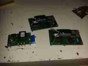
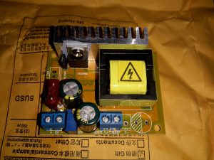
Going through eBay recently looking for parts for a couple of CRT-based projects, I came across these DC-DC converters.
Apparently rated from 45-390v DC output at 200mA, these should be ideal for driving some of the electrodes (focus, screen, grid) in a CRT.
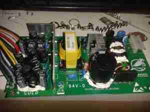
Above is the top of the board, input voltage header on the left, output voltage adjust in the centre & output voltage header on the right.
This module has a mini-automotive fuse, at 10A for input protection.
On the heatsink is mounted the main switching MOSFET, a RU7088R from Ruichips. This FET is fairly heavily rated at 70v 80A, with 6.5mΞ© on-resistance.

PCB Bottom
PCB Bottom

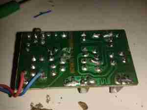
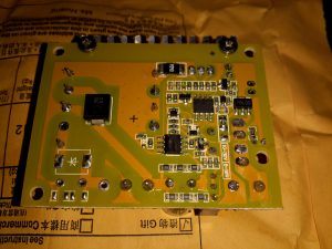
The bottom of the board has the control components, with a pair of ICs. Unfortunately the numbers have been scrubbed off, so no identification here. The output from the transformer is rectified with a single large SMD diode on the left side of the board.
There’s also plenty of isolation gap between the HV output trace & the low voltage logic side of the circuit, the two being bridged only by a resistive divider for output voltage measurement.

Posted on Leave a comment

eBay Airbrush & Compressor

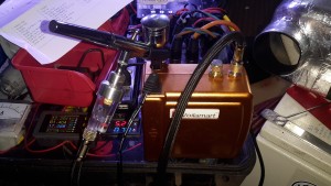
For my latest project, I needed an easier way to paint without messing about with brushes, and the associated marks they leave in a paint job. eBay provided me with a cheap airbrush & compressor.

Airbrush Kit
Airbrush Kit

For less than Β£30, this kit doens’t look so bad. I’ve never used an airbrush before, but I’ve had no problems with this as yet spraying both water based paints & solvent based paints.

Compressor
Compressor

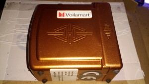
Here’s the compressor itself, this runs on 12v & has an output pressure of 1.5 Bar, which is supposed to be adjustable.

Compressor Internals

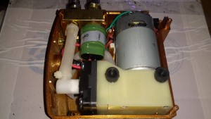
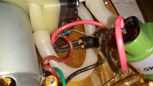
Removing a couple of screws reveals the internal components. Nothing much unusual here, a DC diaphragm pump, pressure switch & outlet fittings. There’s also a thermal cutout fitted next to the motor for protection.
The pressure switch attached to the manifold trips at 1.5Bar, keeping the pressure to the brush pretty much constant.

Air Block
Air Block

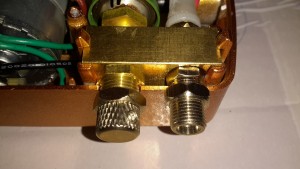
Next to the air outlet fitting is an adjustment knob, supposedly for varying the pressure. However it’s just a piss-poorly designed adjustable relief valve that vents to atmosphere. There’s not much of a control range.

Messy Wiring
Messy Wiring

The wiring gets a bit messy where the power LED is concerned, with no heatshrink over the solder joints, but it’s adequate.

Airbrush
Airbrush

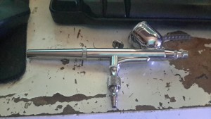
The airbrush itself isn’t too bad. It’s solid Brass, with a very nice Chrome finish. I’m not expecting miracles from a very cheap tool, but it certainly seems to be reasonable.

Water Trap
Water Trap

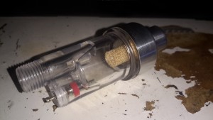
A moisture trap is supplied for the brush, to prevent water drops being sprayed out with the paint. Very handy.

Posted on Leave a comment

“SolarStorm” eBay 4x 18650 Battery Pack

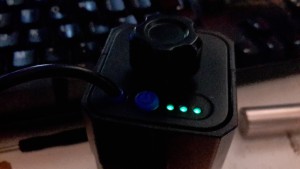
Pack Top
Pack Top

Since the 4×18650 battery pack supplied with my Cree head torch is pretty shit, even by China’s standards, I figured something I could put my own cells into would be a better option. An eBay search turned up these battery boxes, not only with a direct battery output for my torch, but also a USB port for charging other devices when I’m low on charge.
LED Capacity Indicator

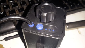
The output to the lamp connector is directly connected to the battery, through the usual Lithium Ion protection, but the USB output is controlled from a single power button. Battery charge condition is displayed on 3 LEDs. Not sure why they used blue silicone for the seal & then used green LEDs… But it does work, even if a little dim.

Label
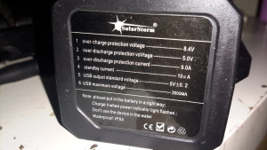
Label

Essential information. Does claim to be protected, and from the already existing electronics for the USB this would be expected in all but the cheapest crap.
An IP rating of IPX4 is claimed, yet just above that rating is a notice not to be used in water. Eh?
This is sealed with an O-Ring around the edge of the top cap & silicone seals around the cable & retaining screw. I did test by immersion in about 6″ of water, and it survived this test perfectly fine, no water ingress at all.

Interconnect Straps
Interconnect Straps

The casing holds a PCB at the bottom end with the cell straps.

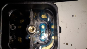
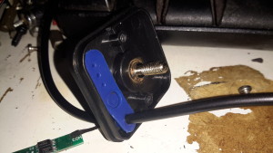
Screw Post
Screw Post

Someone wasn’t that careful at getting the brass screw insert properly centred in the injection mould when they did this one. It’s mushed off centre, but i’s solidly embedded & doesn’t present any problems to usability.

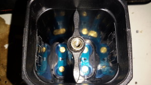
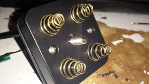
Cell Springs
Cell Springs

The top cover holds the cell springs & the electronics.

Button & Cable Seal
Button & Cable Seal

Removing the pair of screws allows the top cap to open up. The cable, button & LEDs are robustly sealed off with this silicone moulding.

Top Removed
Top Removed

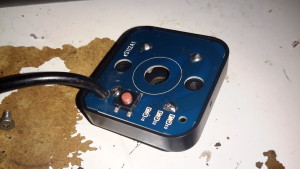
Here’s the PCB, not much on the top, other than the power button & battery indicator LEDs.

Electronics
Electronics

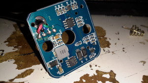
Desoldering the cell springs allows the PCB to pop out of the plastic moulding. There’s more than I expected here!

Bottom left is a DC-DC converter, generating the +5v rail for the USB port, this is driven with an XL1583 3A buck converter IC.

Bottom right is the protection IC & MOSFETs for the Lithium Ion cells. I wasn’t able to find a datasheet for the tiny VA7022 IC, but I did manage to make certain it was a 7.4v Li-Ion protection IC.

Top right is a completely unmarked IC, and a 3.3v SOT-23 voltage regulator. I’m assuming that the unmarked IC is a microcontroller of some sort, as it’s handling more than just the battery level LEDs.

A pretty decent 4-core cable finishes the job off. For once there’s actually some copper in this cable, not the usual Chineseuim thin-as-hair crap.

Posted on Leave a comment

Multifunction LCD Power Meter MHF-8020P

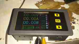
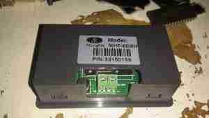
LCD Unit
LCD Unit

I recently came across these on eBay, so I thought I’d grab one to see how they function, with all the metrics they display, there’s potential here for them to be very useful indeed.
One of the best parts is that no wiring is required between the sensor board & the LCD head unit – everything is transmitted over a 2.4GHz data link using NRF24L01 modules.
Above is the display unit, with it’s colour LCD display. Many features are available on this, & they appear to be designed for battery powered systems.

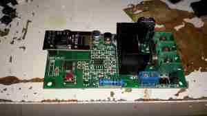
Monitor PCB
Monitor PCB

Another PCB handles the current & voltage sensing, so this one can be mounted as close to the high current wiring as possible.

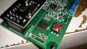
Monitor PCB Microcontroller

The transmitter PCB is controlled with an STM8S003F3 microcontroller from ST Microelectronics. This is a Flash based STM with 8KB of ROM, 1KB of RAM & 10-bit ADC. The NRF24L01 transceiver module is just to the left.
There’s only a single button on this board, for pairing both ends of the link.

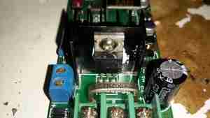
Output MOSFET
Output MOSFET

The high current end of the board has the 0.0025Ξ© current shunt & the output switch MOSFET, a STP75NF75 75v 75A FET, also from ST Microelectronics. A separate power source can be provided for the logic via the blue terminal block instead of powering from the source being measured.

LCD Unit Rear
LCD Unit Rear

Here’s the display unit, only a pair of power terminals are provided, 5-24v wide-range input is catered for.

LCD Unit PCB
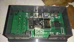
LCD Unit PCB

Unclipping the back of the board reveals the PCB, with another 2.4GHz NRF24L01 module, and a STM8S005K6 microcontroller in this case. The switching power supply that handles the wide input voltage is along the top edge of the board.

Unfortunately I didn’t get any instruction manual with this, so some guesswork & translation of the finest Chinglish was required to get my head round the way everything works. To make life a little easier for others that might have this issue, here’s a list of functions & how to make them work.

LCD Closeup
LCD Closeup

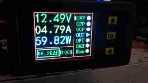
On the right edge of the board is the function list, a quick press of the OK button turns a function ON/OFF, while holding it allows the threshold to be set.
When the output is disabled by one of the protection functions, turning that function OFF will immediately enable the output again.
The UP/DOWN buttons obviously function to select the desired function with the cursor just to the left of the labels. Less obviously though, pressing the UP button while the very top function is selected will change the Amp-Hours display to a battery capacity icon, while pressing DOWN while the very bottom function is selected will change the Watts display to Hours.
The round circle to the right displays the status of a function. Green for OK/ON Grey for FAULT/OFF.
  • OVP: Over voltage protection. This will turn off the load when the measured voltage exceeds the set threshold.
  • OPP: Over power protection. This function prevents a load from pulling more than a specified number of watts from the supply.
  • OCP: Over current protection. This one’s a little more obvious, it’ll disable the output when the current measured exceeds the specified limit.
  • OUT: This one is the status of the output MOSFET. Can also be used to manually enable/disable the output.
  • OFT: Over time protection. This one could be useful when charging batteries, if the output is enabled for longer than the specified time, the output will toggle off.
  • OAH: Over Amp-Hours protection. If the counted Amp-Hours exceeds the set limit, the output will be disabled.
  • Nom: This one indicates the status of the RF data link between the modules, and can be used to set the channel they operate on.
    Pairing is achieved by holding the OK button, selecting the channel on the LCD unit, and then pressing the button on the transmitter board. After a few seconds, (it appears to scan through all addresses until it gets a response) the display will resume updating.
    This function would be required if there are more than a single meter within RF range of each other.

I’ve not yet had a proper play with all the protection functions, but a quick mess with the OVP setting proved it was very over-sensitive. Setting the protection voltage to 15v triggered the protection with the measured voltage between 12.5v-13.8v. More experimentation is required here I think, but as I plan to just use these for power monitoring, I’ll most likely leave all the advanced functions disabled.

Posted on Leave a comment

De La Rue Coin Counting Machine

Here’s some teardown photos of an old De La Rue coin counter, used in businesses for rapid counting of change into large bags.

Mechanism
Mechanism

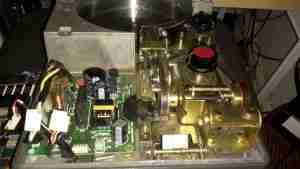
An overview of the whole mechanical system of the counter. Coins are loaded into the drum at the rear of the machine, which sorts them into a row for the rubber belt to pick up & run through the counter. The coin type to be sorted is selected by turning the control knobs on the right.
The control knobs adjust the width & height of the coin channel so only the correct sized coins will be counted.

PSU & Switching
PSU & Switching

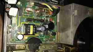
The counter is driven by a basic AC induction motor, the motor power relay & reversing relay is on this PCB, along with the 5v switching supply for the main CPU board.
The SMPS on this board looks like a standard mains unit, but it’s got one big difference. Under the frame next to the main motor is a relatively large transformer, with a 35v output. This AC is fed into the SMPS section of the PSU board to be converted to 5v DC for the logic.
I’m not sure why it’s been done this way, and have never seen anything similar before.
The edge of the coin channel can be seen here, the black star wheel rotates when a coin passes & registers the count.

Controller PCB
Controller PCB

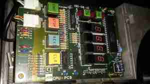
Here’s the main controller PCB, IC date codes put the unit to about 1995. The main CPU is a NEC UPD8049HC 8-bit micro, no flash or EEPROM on this old CPU, simply mask ROM. Coin readout is done on the 4 7-segment LED displays. Not much to this counter, it’s both electronically & mechanically simple.

Counter Sensor
Counter Sensor

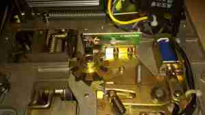
Coin counting is done by the star wheel mentioned above, which drives the interrupter disc on this photo-gate. The solenoid locks the counter shaft to prevent over or under counting when a set number of coins is to be counted.

Motor Run Capacitor
Motor Run Capacitor

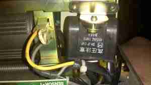
Under the frame, here on the left is the small induction motor, only 6W, 4-pole. The run cap for the motor is in the centre, and the 35v transformer is just visible behind it.

Main Motor Drive
Main Motor Drive

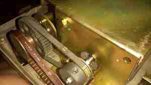
Main drive to the coin sorting mech is through rubber belts, and bevel gears drive the coin drum.

Posted on 2 Comments

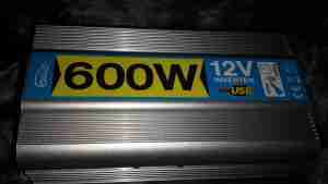
Maplin 600W “Modified Sine” Power Inverter

Maplin 600W Inverter

I’m no fan of power inverters. In my experience they’re horrifically inefficient, have power appetites that make engine starter motors look like electric toothbrushes & reduce the life expectancy of lead-acid batteries to no more than a few days.
However I have decided to do a little analysis on a cheapo “600W” model that Maplin Electronics sells.

Cover Removed
Cover Removed

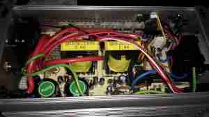
After a serious amount of metallic abuse, the bottom cover eventually came off. The sheet of steel used to close the bottom of the aluminium extrusion was wedged into place with what was probably a 10 ton hydraulic press.
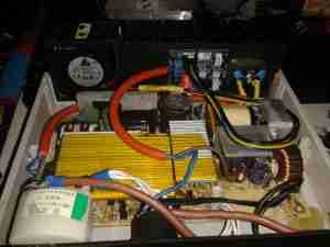
As can be seen from the PCB, there’s no massive 50Hz power transformer, but a pair of high frequency switching transformers. Obviously this is to lighten the weight & the cost of the magnetics, but it does nothing for the quality of the AC output waveform.

DC Input End
DC Input End

The 12v DC from the battery comes in on very heavy 8-gauge cables, this device is fused at 75A!

DC Fuses
DC Fuses

Here’s the fusing arrangement on the DC input stage, just 3 standard blade-type automotive fuses. Interestingly, these are very difficult to get at without a large hammer & some swearing, so I imagine if the user manages to blow these Maplin just expect the device to be thrown out.

Input DC-DC Switching MOSFETs

On the input side, the DC is switched into the pair of transformers to create a bipolar high voltage DC supply.

High Voltage Rectifiers

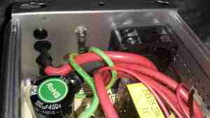
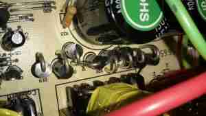
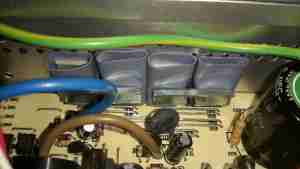
The large rectifier diodes on the outputs of the transformers feed into the 400v 100Β΅F smoothing capacitors.
As mains AC is obviously a bipolar waveform, I’m guessing this is generating a Β±150v DC supply.

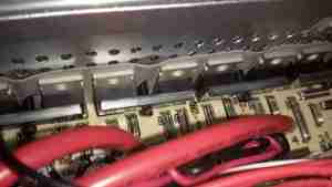
Output MOSFETs
Output MOSFETs

After the high voltage is rectified & smoothed, it’s switched through 4 more MOSFETs on the other side of the PCB to create the main AC output.

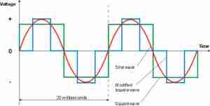
The label states this is a modified-sine output, so I’d expect something on the scope that looks like this:

Inverter Waveforms
Inverter Waveforms

Modified-sine doesn’t look as bad as just a pure square output, but I suspect it’s a little hard on inductive loads & rectifiers.

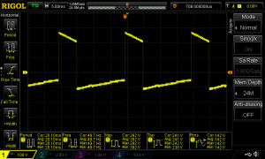
However, after connecting the scope, here’s the actual waveform:

Actual Waveform
Actual Waveform

It’s horrific. It’s not even symmetrical. There isn’t even a true “neutral” either. The same waveform (in antiphase) is on the other mains socket terminal. This gives an RMS output voltage of 284v. Needless to say I didn’t try it under load, as I don’t possess anything I don’t mind destroying. (This is when incandescent lamps are *really* useful. Bloody EU ;)).

About the only thing that it’s accurate at reproducing is the 50Hz output, which it does pretty damn well.

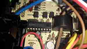
System Microcontroller

As is usual these days, the whole system is controlled via a microcontroller.

Posted on 6 Comments

Eberspacher Tent Heating System

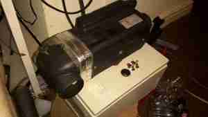
The "Tenterspacher"
The “Tenterspacher”

I go camping on a regular basis here in the UK, and often even in summer it’s horribly cold at night in a field somewhere in the middle of Leicestershire. This doesn’t go too well with my severe aversion to being cold.
For the past several years I’ve used a Tilley lamp for some heat & light while at festivals & general camping, but it’s heat output is less than stellar when used in a 6-man tent.

An Eberspacher diesel heater was what was required for the job. Above is the unit as it’s built at the moment – I’ve used an old D1LCC 1.8kW heater that was recently decommissioned from nb Tanya Louise, as it’s getting a bit funny about what kind of fuel it’ll run on in it’s old age. It’ll work perfectly well on kerosene though – a fuel I already take with me camping for the Tilley.

It’s mounted on a base box, which is a repurposed steel electrical junction box that saw a previous life containing a 3-phase fan motor controller.

Data Plate
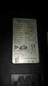
Data Plate

Here’s the info on the heater unit itself. Drawing 22W of power at 12v I’ll be getting 1.8kW of heat output – sounds good to me.


Box Internals
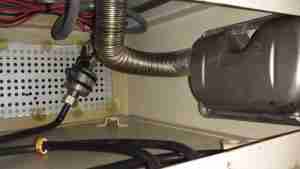
Box Internals

Here’s a view into the base box before the circulation fans were fitted, in early prototype stage. I used a small toroid as a clunk on the end of the rubber fuel line πŸ˜‰

Support Components
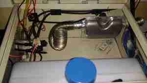
Support Components

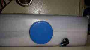
After a few bits from the Great eBay arrived, here’s the internals of the base unit at present. The fuel tank is a repurposed 2L fridge water container – made of tough HDPE so it’s fuel resistant.
The fuel pump is mounted on the left side next to the tank – having been wrapped in some foam to deaden the continual ticking noise it creates. The exhaust & it’s silencer are mounted at the rear, the silencer being retained by a surplus rubber shock mount. Luckily the exhaust systems on these heaters don’t get particularly hot, so the rubber doesn’t melt.
The exhaust outlet is routed through the frame, to be attached to an external hose. I don’t want combustion gases in the tent with me!

Standard Eberspacher silencers also aren’t gas-tight from the factory – they’re designed to be used in the open on the underframe of a vehicle, so I’ve covered all the seams in aluminium tape to make the system airtight.

Ventilation
Ventilation

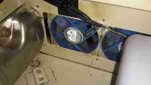
To make sure that the support components don’t get overheated with the exhaust being in such close proximity, and to pull a little more heat out of the system, a pair of slow-running 80mm fans has been fitted to the end of the box. These blow enough air through to give a nice warm breeze from the vents on the other end of the base.

Fuel Tank
Fuel Tank

The tank I’ve used just so happened to be the perfect size to fit into the base box, and to tap the fuel off a bulkhead fitting was put into the top of the tank, with a dip tube on the other side. The fuel line itself is tiny – only 4mm.
If the specifications from Eberspacher are to be believed, 2L of fuel on board will allow the system to run for about 8 hours on full power, or 16 hours on minimum power.

Being inside the base, refuelling is a little awkward at the moment, the heater has to completely cool before the exhaust can be detached without receiving a burn, so I’ll be building in a fuel transfer system from an external jerry can later to automate the process – this will also help to avoid messy fuel spills.

More to come when the rest of the system is worked out!

73s for now!

Posted on Leave a comment

Totally Wicked Forza / JoyeTech eVIC 60W Teardown

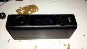
Display
Display

I’ve been a vaper now for many years, after giving up the evil weed that is tobacco. Here’s my latest acquisition in the vaping world, the JoyeTech eVIC 60W. This one is branded by Totally Wicked as the Forza VT60.

18650 Cell
18650 Cell

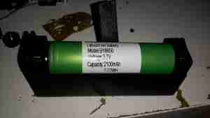
Powered by a single 18650 Li-Ion cell, this one is a Sony VTC4 series, 2100mAh.

Under the battery a pair of screws hold the electronics in the main cast alloy casing.

OLED Display
OLED Display

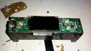
After removing the screws, the entire internal assembly comes out of the case, here’s the top of the PCB with the large OLED display in the centre.

USB Jack
USB Jack

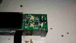
On the right side of the board is the USB jack for charging & firmware updates. The adjustment buttons are also at this end.

Output
Output

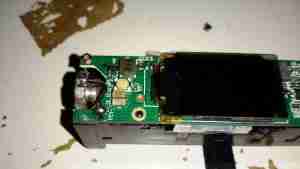
On the left side of the board is the main output connector & the fire button. Unlike many eCigs I’ve torn down before, the wiring in this one is very beefy – it has to be to handle the high currents used with some atomizers – up to 10A.
PCB Reverse
PCB Reverse

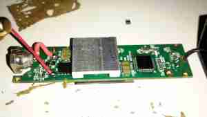
Removing the board from the battery holder shows the main power circuitry & MCU. The aluminium heatsink is thermally bonded to the switching MOSFETs, a pair under each end. The switching inductor is under the gap in the centre of the heatsink.

DC-DC Converter
DC-DC Converter

A close up of the heatsink shows the very slim inductor under the heatsink.

Microcontroller
Microcontroller

The main MCU in this unit has a very strange part number, which I’ve been unable to find information on, but it’s probably 8081 based.

Posted on Leave a comment

Duratool ZD-915 12v Conversion

Inkeeping with everything else in my shack being low voltage operated, I had planned from the outset to convert the desoldering station to 12v operation. It turns out this has been the easiest tool to convert in my shack so far.

PSU Outputs
PSU Outputs

The factory SMPS is a fairly straightforward 18v 12A unit, with only a single small oddity: the desoldering gun’s heating element is controlled from inside the supply.

Iron MOSFET
Iron MOSFET

Next to the output rectifier on the heatsink is a large MOSFET, in this case a STP60NF06 from ST Micro. This is a fairly beefy FET at 60v & 60A capacity, RDS On of <0.016Ξ©.
This is driven via an opto-isolator from the main logic board. I’ve not yet looked at the waveform on the scope, but I suspect this is also being PWM’d to control temperature better when close to the set point.

Iron Element Controller

Rather than fire up the soldering iron & build a new element controller circuit (Lazy Modeβ„’), I opted to take a saw to the original power supply. I cut the DC output section of the PCB off the rest of the supply & attached this piece back to the frame of the base unit. I also added a small heatsink to the MOSFET to make sure it stays cool.

12v Power Supply
12v Power Supply

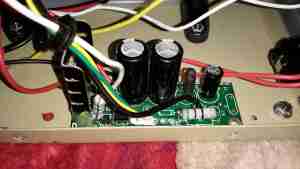
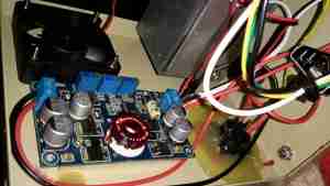
Since the fan & vacuum pump are both already 12v rated, those are connected directly to the DC input socket, that I’ve installed in place of the original IEC mains socket. The 18v for the heating element is generated by a 10A DC-DC converter, again from eBay.

Oddly, the iron itself is rated at 24v 80W, but the factory supply is only rated to 18v. I’m not sure why they’ve derated the system, but as the station already draws up to 10A from a 13.8v supply, increasing the voltage any further would start giving my DC supplies a problem, so it can stay at 18v for now.

Posted on 3 Comments

Duratool ZD-915 Vacuum Desoldering Station Teardown

For a long time I’ve needed a decent vacuum desoldering tool, as I do much stripping of old PCBs for random parts.
Solder wick works well for most things, but it’s expensive & can be fiddly. It also doesn’t keep very long as the copper braid oxidises & after that point it never seems to work particularly well, even when soaked in fresh flux.

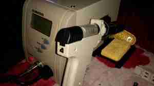
Desoldering Station
Desoldering Station

As usual eBay to the rescue! I managed to pick this one up for Β£80.

Vacuum Pump
Vacuum Pump

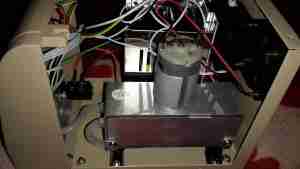
Removing the lid reveals the internals. Front & centre is the vacuum pump, with the mains supply behind it. There’s also a very noisy cooling fan at the back. Not sure why since the unit never gets warm enough to actually warrant a fan.

PSU
PSU

On the other side is the PSU. This is an 18v 12A rated SMPS, with a bit of custom electronics for controlling the iron element. Mounted to the back case is a small black box, more to come on this bit.

PSU Board
PSU Board

Cracking the case of the PSU reveals a pretty bog-standard SMPS, with a surprising amount of mains filtering for a Chinese supply. The DC outputs are on the right.

20160101_111613

From the rail markings, this is clearly designed to output some more voltage rails – possibly for other models of unit. In this case though, a single 18v rail is present. The iron’s element connects directly to the supply, controlled via an opto-isolated MOSFET.

Chinese Voltage Regulation

As both the fan & the vacuum pump motor are 12v devices, some provision had to be made to reduce the 18v from the power supply to a more reasonable value. Inside the black plastic box are a pair of 1Ξ© 5W power resistors, connected in series. The output from this connects to the fan & vacuum pump. Because cheap, obviously.

Controller
Controller

Finally, here’s the controller PCB, the main MCU is an 8081 derivative, with a Holtek HT1621B LCD controller for the front panel temperature readout. Iron temperature is achieved by a thermocouple embedded in the heater, I imagine the potentiometer on the left side of the PCB is for calibration.

Posted on Leave a comment

Cheap Lithium Polymer Battery Packs

In the past, I’ve used RC type LiPo packs for my mobile power requirements, but these tend to be a bit bulky, since they’re designed for very high discharge current capability – powering large motors in models is a heavy job.

I recently came across some Samsung Galaxy Tab 10.1 battery packs on eBay very cheaply, at Β£2.95 a piece. For this price I get 6800mAh of capacity at 4.2v, for my 12v requirements, 3 packs must be connected in series, for a total output of 12.6v fully charged.

For an initial pack, I got 9 of these units, to be connected in 3 sets of 3 to make 20Ah total capacity.There are no control electronics built into these batteries – it’s simply a pair of 3400mAh cells connected in parallel through internal polyfuses, and an ID EEPROM for the Tab to identify the battery.
This means I can just bring the cell connections together with the original PCB, without having to mess with the welded cell tabs.

Battery Pack
Battery Pack

Here’s the pack with it’s cell connections finished & a lithium BCM connected. This chemistry requires close control of voltages to remain stable, and with a pack this large, a thermal runaway would be catastrophic.

Cell Links
Cell Links

The OEM battery connector has been removed, and my series-parallel cell connections are soldered on, with extra lead-outs for balancing the pack. This was the most time-consuming part of the build.

If all goes well with the life of this pack for utility use, I’ll be building another 5 of these, for a total capacity of 120Ah. This will be extremely useful for portable use, as the weight is about half that of an equivalent lead-acid.

Posted on Leave a comment

Cree XML-T6 x5 LED Torch

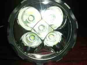
Here’s another torch from eBay, this time with 5 Cree XML-T6 LEDs.

Label
Label

Having 5 Cree LEDs rated at up to 3A a piece, this light has the capacity to draw about 50W from it’s power supply. In this case though, current draw is about 1.5A at 12v input on the full brightness setting.

Cree LED Torch
Cree LED Torch

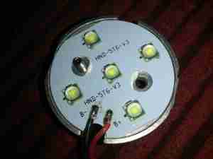
Here’s the LEDs mounted into the reflector. Fitting this many high power LEDs into a small space requires some serious heatsinking. The casing is made of machined aluminium.

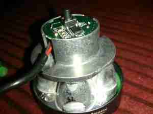
LED Module
LED Module

Unscrewing the front bezel allows the internals to come out. The core frame & reflector is all cast alloy as well, for heatsinking the LEDs. The controller PCB is mounted into a recess in the back of the LED mount.

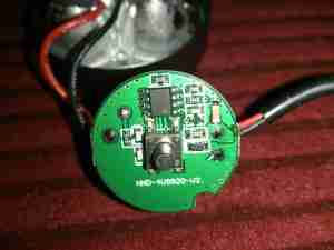
Controller
Controller

Here’s the controller itself. The usual small microcontroller is present, for the multiple modes, and handling the momentary power switch.

Switching Inductor
Switching Inductor

As all the LEDs on this torch are connected in series, their forward voltage is ~12-15v. The battery is an 8.4v Li-Ion pack, so some boost conversion is required. This is handled by the circuitry on the other side of the board, with this large power inductor.

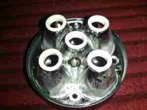
Reflector
Reflector

The reflector screws onto the front of the LED array, centered in place with some plastic grommets around the LEDs themselves.

LED Array
LED Array

Finally for the torch, the LED array itself. This is attached to the frame with some thermal adhesive, and the LEDs themselves are mounted on an aluminium-core PCB for better heat transfer.
This module unsurprisingly generates quite some heat, so I have improved the thermal transfer to the outer case with some thermal grease around the outer edge.

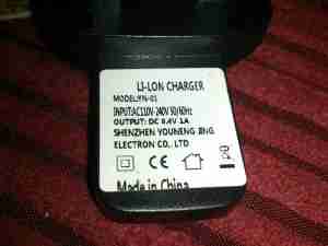
Charger
Charger

The supplied charger is the usual Chinese cheapy affair, claiming an output current of 1A at 8.4v. I never use these chargers, so they get butchered instead.

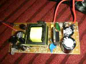
Charger PCB
Charger PCB

Here’s the main PCB. Overall the construction isn’t that bad, the input mains is full-wave rectified, but there is little in the way of RFI filtering. The supply is fused, but with an absolutely tiny glass affair that I seriously doubt has the ability to clear a large fault current.
Like many cheap supplies, the output wiring is very thin, it’s capacity to carry 1A is questionable.

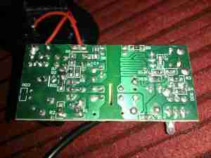
PCB Reverse
PCB Reverse

On the reverse side, there’s a nice large gap between the mains side & the low voltage output. There’s even an anti-tracking slot under the optoisolator.

Posted on Leave a comment

Another Chinese Charger

I almost forgot about this bit of kit, that came with one of my LED torches as a Lithium Ion charger. As I never plug in anything that comes from China via eBay, here’s the teardown & analysis.

Another Lethal Charger?

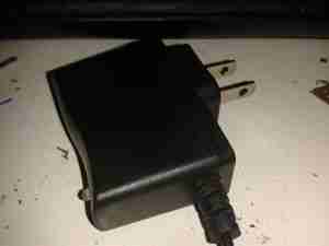
Here’s the unit itself. It’s very light, and is clearly intended for American NEMA power points.

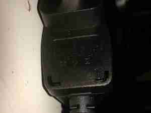
Specs
Specs

Claimed specifications are 100-240v AC input, making it universal, and 4.2v DC out Β±0.5v at 500mA.
Considering the size of the output wire, if this can actually output rated voltage at rated current I’ll be surprised.

Opened
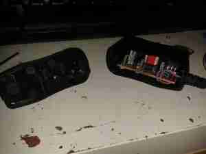
Opened

Here’s the adaptor opened up. There’s no mains wiring to speak of, the mains pins simply push into tags on the PCB.

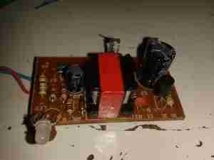
PCB Top
PCB Top

Top of the SMPS PCB. As usual with Chinese gear, it’s very simple, very cheap and likely very dangerous. There’s no real fusing on the mains input, only half-wave rectification & no EMI filtering.

PCB Bottom
PCB Bottom

Here’s the bottom of the PCB. At least there’s a fairly sized gap between the mains & the output for isolation. The wiggly bit of track next to one of the mains input tags is supposed to be a fuse – I somehow doubt that it has the required breaking characteristics to actually pass any safety standards. Obviously a proper fuse or fusible resistor was far too expensive for these.

The output wiring on the left is thinner than hair, I’d say at least 28AWG, and probably can’t carry 500mA without suffering extreme volt drop.

Posted on Leave a comment

DIY SMPS Fan Controller

Now the controllers have arrived, I can rejig the supplies to have proper thermal control on their cooling.

Changes Overview
Changes Overview

Here’s the top off the PSU. The board has been added to the back panel, getting it’s 12v supply from the cable that originally fed the fan directly. Luckily there was just enough length on the temperature probe to fit it to the output rectifier heatsink without modification.

To connect to the standard 4-pin headers on the controller, I’ve spliced on a PC fan extension cable, as these fans spent their previous lives in servers, with odd custom connectors.

Fan Controller
Fan Controller

Here’s the controller itself, the temperature probe is inserted between the main transformer & the rectifier heatsink.
I’ve set the controller to start accelerating the fan at 50Β°C, with full speed at 70Β°C.

Full Load Test
Full Load Test

Under a full load test for 1 hour, the fan didn’t even speed up past about 40% of full power. The very high airflow from these fans is doing an excellent job of keeping the supply cool. Previously the entire case was very hot to the touch, now everything is cool & just a hint of warm air exits the vents. As the fan never runs at full speed, the noise isn’t too deafening, and immediately spools back down to minimum power when the load is removed.

Posted on Leave a comment

DIY SMPS Fan Speed Control – The Controllers

Finally, after a couple of weeks wait time, the fan controllers for the power supplies have arrived. They’re small boards, which is good for the small space left inside the case of the supply.

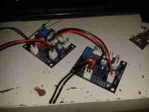
Controller Boards
Controller Boards

Here they are. I’m not certain what the pair of potentiometers are for – there’s no mention of them in the documentation. Possibly for calibration.
Beepers are supplied so an alarm can be heard if the fan fails – very useful for this application.

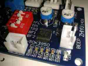
Controller Closeup
Controller Closeup

Here’s a closeup of the PCB. Options are set with the DIP switch bank on the left, details for that below. The main IC is a STM8S103F3 flash microcontroller.

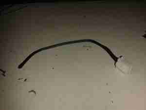
Temperature Probe
Temperature Probe

The only issue at the moment is that the temperature probe leads are much too short. I’ll have to make a small modification to get enough length here.


Here’s all the details on the boards, more for future reference when they undoubtedly vanish from eBay πŸ˜‰

Specifications

WorkingΒ voltage:DC12V

CircuitΒ loadΒ capacity:Β maximumΒ currentΒ perΒ outputΒ 5A,Β theΒ busΒ currentsΒ upΒ 9A

OutputΒ Range:Β TheΒ firstΒ channelΒ 20%Β -100%,Β orΒ 40%Β -100%Β (TFLΒ =Β ON)
TheΒ secondΒ channelΒ andΒ theΒ thirdΒ channelΒ 10%Β -100%

(Note:Β AboveΒ rangeΒ onlyΒ forΒ PWMΒ range,Β theΒ actualΒ controlΒ effectΒ willΒ varyΒ dependingΒ onΒ theΒ fan.)

TemperatureΒ probeΒ parameters:Β 50KΒ BΒ =Β 3950

ThermostatΒ temperatureΒ zoneΒ error:Β errorΒ dependingΒ onΒ theΒ temperatureΒ probe,Β generallyΒ 3-5%

StallΒ alarmΒ minimumΒ speed:Β 700-800Β rpm


FunctionΒ settingΒ switchΒ Description:

TFLΒ (No.Β 1):Β TheΒ lowestΒ temperatureΒ channelΒ PWMΒ setting,Β whenΒ ONΒ stateΒ FAN1Β PWMΒ minimumΒ isΒ 40%,Β whenΒ OFFΒ theΒ minimumΒ PWMΒ ofΒ FAN1Β isΒ 20%.

TP1Β TP2Β (No.Β 2,3):Β TemperatureΒ channelΒ controlΒ temperatureΒ zonesΒ areΒ interpretedΒ asΒ followsΒ (needΒ toΒ usedΒ withΒ theΒ temperatureΒ probe):


TP1 Β TP2 AcceleratingΒ temperature FullΒ speedΒ temperature
OFF OFF 35℃ 45℃
ON OFF 40℃ 55℃
OFF ON 50℃ 70℃
ON ON 60℃ 90℃


WhenΒ theΒ temperatureΒ lowerΒ thanΒ theΒ acceleratedΒ temperature,Β thenΒ outputΒ atΒ theΒ minimumΒ rotationΒ speed;Β whenΒ itΒ exceedΒ overΒ theΒ fullΒ temperature,Β thenΒ alwaysΒ outputΒ atΒ fullΒ speed.

BF1Β BF2Β (No.Β 4,5):Β correspondsΒ FAN1Β FAN2Β stallΒ alarmΒ functionΒ switch,Β whenΒ theΒ correspondingΒ openΒ channelΒ fanΒ breakΒ down,Β theΒ controllerΒ willΒ alarmΒ withΒ soundandΒ lightΒ (worksΒ withΒ buzzle),Β alarmΒ willΒ automaticallyΒ eliminatedΒ whenΒ theΒ fanΒ isΒ rotatedΒ recoveryΒ .Β IfΒ BF1Β andΒ BF2Β bothΒ areΒ openΒ (ON),Β theΒ FAN1,Β FAN2Β haveΒ anyΒ oneΒ orΒ bothΒ stops,Β theΒ controllerΒ willΒ alarm!

Posted on Leave a comment

Maplin LED Torch Charger Replacement

In my previous post, I mentioned I’d be replacing the factory supplied charging gear with something that actually charges lithium chemistry cells correctly.

Charging Base
Charging Base

Here’s the base as supplied, with an indicator LED on the right hand side. This LED indicates nothing other than power being applied to the charging base. It’s just connected across the power input with a resistor. This also means that any battery left in the charger while it’s unplugged will discharge itself through this LED over time. Great design there China!

PCB Removed
PCB Removed

Here I’ve removed the PCB – there’s no need for it to be taking up any space, as it’s just a complete waste of copper clad board in the first place. The battery tabs have been desoldered & hot snot used to secure them into the plastic casing.

USB Hole
USB Hole

The charger modules I use are USB powered, so a small hole has been routed out in the casing to allow access to the port.

Charging Module
Charging Module

Here the charging module has been installed & wired to the battery tabs. Output is now a nice 4.18v, and will automatically stop charging when the cell is full.
Safety has been restored!

73s for now folks!

Posted on Leave a comment

Maplin 3W LED Torch Charger Fail

A member of the family recently bought one of these torches from Maplin electronics, and the included chargers for the 18650 lithium-ion cells leave a lot to be desired.

Torch
Torch

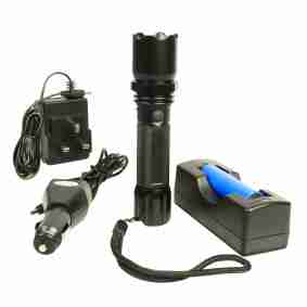
Here’s what’s supplied. The torch itself is OK – very bright, and a good size. Me being cynical of overpriced Chinese equipment with lithium batteries, I decided to look in the charging base & the cigar-lighter adaptor to see if there was any actual charging logic.

Charger
Charger

Answer – nope. Not a single active component in here. It’s just a jack connected to the battery terminals. There’s all the space there to fit a proper charging circuit, but it’s been left out to save money.

OK then, is it inside the cigarette lighter adaptor?

Lighter Adaptor
Lighter Adaptor

Nope. Not a single sign of anything resembling a Lithium-Ion charger IC. There’s a standard MC34063A 1.5A Buck converter IC on the bottom of the PCB, this is what’s giving the low voltage output for the torch.

Charger Bottom
Charger Bottom

Here’s the IC – just a buck converter. The output voltage here is 4.3v. This is higher than the safe charging voltage of a lithium ion cell, of 4.2v.

The cells supplied are “protected” versions, having charge/discharge protection circuitry built onto the end of the cell on a small PCB, this makes the cell slightly longer than a bare 18650, so it’s easy to tell them apart.
The manufacturers in this case are relying on that protection circuit on the cell to prevent an overcharge condition – this isn’t the purpose they’re designed for, and charging this way is very stressful for the cells. I wouldn’t like to leave one of these units charging unattended, as a battery explosion might result.

More to come shortly when I build a proper charger for this torch, so it can be recharged without fearing an alkali metal fire!

73s for now folks!

Posted on Leave a comment

DIY SMPS Cooling

The power supplies I have recently built from surplus Cisco switch boards have started displaying a rather irritating problem – continual load of over 9A causes the supplies to shut down on overheat.

This was partially expected, as the original switches that these supplies came from are cooled by a monster of a centrifugal blower that could give a Dyson a run for it’s money. The problem with these fans is that they’re very loud, draw a lot of power (3-4A) and aren’t small enough to fit into the case I’ve used for the project.

The solution of course, is a bigger fan – I’ve got some Delta AFB0612EHE server fans, these are very powerful axial units, shifting 60CFM at 11,000RPM, with a power draw of 1.12A.
They’re 60mm diameter, so only just fit into the back of the case – although they stick out of the back by 40mm.

Monster Fan
Monster Fan

Here’s the fan, not the beefiest I have, but the beefiest that will fit into the available space.
These will easily take fingers off if they get too close at full speed, so guards will definitely be required.

To reduce the noise (they sound like jet engines at full pelt), I have ordered some PWM controllers that have a temperature sensor onboard, so I can have the fan run at a speed proportional to the PSU temperature. I will probably attach the sensor to the output rectifier heatsink, since that’s got the highest thermal load for it’s size.

More to come when parts arrive!

73s for now πŸ™‚

Posted on Leave a comment

Rigol DS1054Z 12v Power Supply Noise Filtering

Since I fitted my scope with a SMPS based 12v input supply, there has been a noise problem on very low volts/div settings, this noise isn’t present on the mains supply, so I can only think it’s coming from the switching frequencies of the various DC-DC modules I’ve used.

Scope Ripple
Scope Ripple

Because of this I’ve designed a linear post-regulation stage for the supply, to remove the RFI from the DC rails.
This board takes the outputs from the DC-DC converters, removes all the noise & outputs clean DC onto the mainboard of the scope.

As the scope internally uses regulation to get the voltages lower, I’ve found that I don’t have to match the outputs of the mains supply exactly, for the +/-17.5v rails, 12v is perfectly fine instead.

Scope Linear PSU
Scope Linear PSU

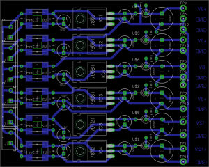
Here’s the PCB layout, with the 6Β  common mode filters on the input (left), linear regulator ICs in the centre & the output filters on the right.

Scope Linear PSU
Scope Linear PSU

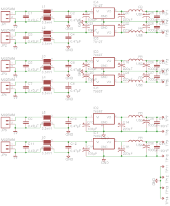
Here’s the schematic layout, as usual the Eagle Project files are in the link below, I’ll update when I have built the board & tested!

[download id=”5589″]

73s for now πŸ™‚

Posted on Leave a comment

USB1100 Digital Message Unit

This is basically an industrial, rugged MP3 player, in an extruded aluminium case.
They are used in commercial settings for generating telephone hold music or continual playback of background music in shops.

USB1100
USB1100

It’s quite a compact unit, in a nice aluminium case, designed for mounting into a comms setup. This unit will play any MP3 file, up to a maximum size of 11MB.

Connections
Connections

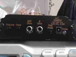
Here’s the user connections on the end of the unit. The device takes a standard 12v DC input, and has a single button for setup, user feedback is given through the multi-colour LED next to the power jack.
Both 8Ξ© & 600Ξ© audio outputs are provided for maximum compatibility. Volume & tone controls are also here.
On the other end of the unit is a single USB port for loading the audio files from a USB drive, and a reset button.

Main PCB
Main PCB

Here’s the single PCB removed from the casing. Unfortunately the main CPU has had it’s part number sanded off, and I can’t be bothered to try & find out what kind of processor it is at this point. To the right of the CPU are some flash ROM & SDRAM, along with the single USB port at bottom right.
The left side of the board is dedicated to audio output & voltage regulation, there are a fair few linear regulators in this unit.

Audio End
Audio End

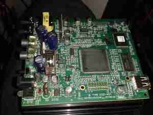
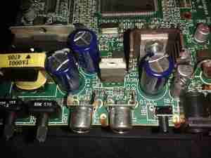
Here’s the audio output side of the board, the transformer on the left is to provide the 600Ξ© output, the audio amplifier IC (BA5416) is just behind it. To the right are some of the main voltage regulators, a 5v one on the heatsink & a LM317.

Audio Codec
Audio Codec

The audio codec is a CS4271 from Cirrus Logic, a really high quality part, 24-bit resolution, 192kHz Stereo codec. Considering this is for telephone & PA systems that aren’t that high fidelity, it’s well built!

Posted on Leave a comment

15v Bipolar Supply Testing

Here’s some testing of the first bipolar supply for the Rigol scope. This is the +/-7.5v supply.

Bipolar Supply
Bipolar Supply

Above is the supply built with it’s output filtering. The modules used are a PTN78020W for the positive rail & a PTN78060A for the negative rail.

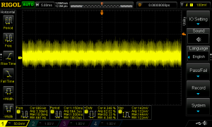
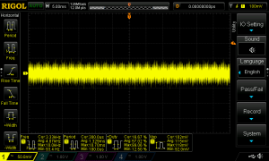
Under a 1A load across the total 15v output, here’s some scope traces of the ripple on the supply:

+7.5v Rail
+7.5v Rail

Here’s the ripple on the +7.5v rail of the supply, there’s about 75mV of total ripple.

-7.5v Rail
-7.5v Rail

And here’s the -7.5v rail, the ripple on this is slightly lower, at about 50mV. This should be more than satisfactory as the scope has onboard linear regulation after the switching supply.

Posted on Leave a comment

Rigol DS1054Z 12v Conversion Project Update

While searching around for regulators to convert my new scope to 12v power, I remembered I had some DC-DC modules from Texas Instruments that I’d got a while ago. Luckily a couple of these are inverting controllers, that will go down to -15v DC at 15W/3A capacity.

I’ve had to order a new module from TI to do the -17v rail, but in the meantime I’ve been getting the other regulators set up & ready to go.

The DC-DC module I’ve got for the -7.5v rail is the PTN78060A type, and the +7.5v & +5v rails will be provided by the PTN78020W 6A buck regulators.

These regulators are rated well above what the scope actually draws, so I shouldn’t have any issues with power.

DC-DC Modules
DC-DC Modules

Here’s the regulators for the 5v, 7.5v & -7.5v rails, with multiturn potentiometers attached for setting the voltage output accurately. I’ve also attached a couple of electrolytics on the output for some more filtering. I’ll add on some more LC filters on the output to keep the noise down to an absolute minimum. These are set up ready with the exact same output voltage as the existing mains AC switching supply, when the final regulator arrives from TI I will put everything together & get some proper rail readings.

There won’t be a proper PCB for this, as I don’t have the parts in Eagle CAD, and I simply don’t have the energy to draw them out from the datasheets.

More to come when parts arrive!

73s for now πŸ™‚

Posted on 2 Comments

Rigol DS1054Z Power Supply Project

Since everything in my shack is run from 12v, I thought it would be handy to convert my new scope to 12v as well, as 99% of the places I find myself needing test gear are off grid, with no access to mains supplies.

Mains PSU
Mains PSU

Here’s the factory mains SMPS unit from the back of the scope. This is a nice multi-rail unit, with several different outputs, the table below details the wiring of the PSU.

Connector PinPCB PinSignalMeasured VoltageMainboardRectifier RatingWire Colour
51AC_TRIGN/AAC_TRIGN/ABROWN
22+9v_GNDN/AFAN --NAORANGE
113+9V10.16VFAN +2AWHITE
64+5V5.1V5V5A20ARED
135+5V5.1V5V5A20ARED
76GNDN/AGNDN/ABLACK
87GNDN/AGNDN/ABLACK
38+7.5V6.9V6.3V20AYELLOW
109+7.5V6.9V6.3V20AYELLOW
110GNDN/AGNDN/ABLACK
121117.5V17.51V17.5V2ABLUE
912-17.5V-17.36V-17.5V2AGREY
1413GNDN/AGNDN/ABLACK
414-7.5V-6.84V-7.5V2AGREEN

The only feature I will lose if I make this switch is AC line triggering, but I never use that anyway, so it’s not a big issue for me.

The connector used by Rigol to connect to the mainboard is a Molex Mini Fit Jr. Series 14-way type.

Since I have been able to locate the connector, the plan is to design a replacement low voltage supply unit for the scope, with the same footprint as the original AC mains supply. This will allow me to do a direct swap without causing any damage or modifying the original supply.
This method will allow me to swap the 240v supply back into the scope if I ever come to need it.

I’m planning to use the LTC3863 DC-DC Controller from Linear Tech to generate the negative rails, this will go down to -150v on the output, so it’s pretty much perfect to generate them.

PSU Output Side
PSU Output Side

Here’s the output side of the mains PSU, it has a lot of filtering on the output rails, the two TO220 devices are the output rectifiers for the +5v & +7.5v rails, these are rated at 20A, 60V.

PCB Bottom
PCB Bottom

Here’s the bottom side of the PCB. It’s a really nicely designed PSU, massive isolation gap, spark gaps on the primary side & good filtering. The output side on the left has the rectifier diodes for the other voltage rails, these are only 2A rated, so designing the inverting supply to generate the negative rails will be pretty easy.

From looking at the PCB markings on both the mainboard & the PSU, the +9v rail seems to be used to drive the fan, both silkscreen markings indicate this.
The voltages marked on the PSU & the mainboard connector don’t quite match up though, there’s a small variation in the stated voltage between the two. This is most likely because all of the regulation of the supplies seems to be done on the mainboard, there are several linear regulators, and a few DC-DC switchers. Providing that the replacement supply isn’t noisy it should work fine.

This is backed up by the fact that the mains PSU only seems to regulate the +5v rail – on measuring the rails that’s the only one that’s close to spec.

Mainboard Power
Mainboard Power

Here’s the mainboard power connector, with it’s silkscreen labelling on the pins. (Very useful). As can be seen here, there’s at least 5 regulators, of both switching & linear types here, generating both positive & negative rails.


More to come when I have some components!

73s for now πŸ™‚