Here’s the final instalment of the new high gain TV antenna & it’s masthead amplifier.
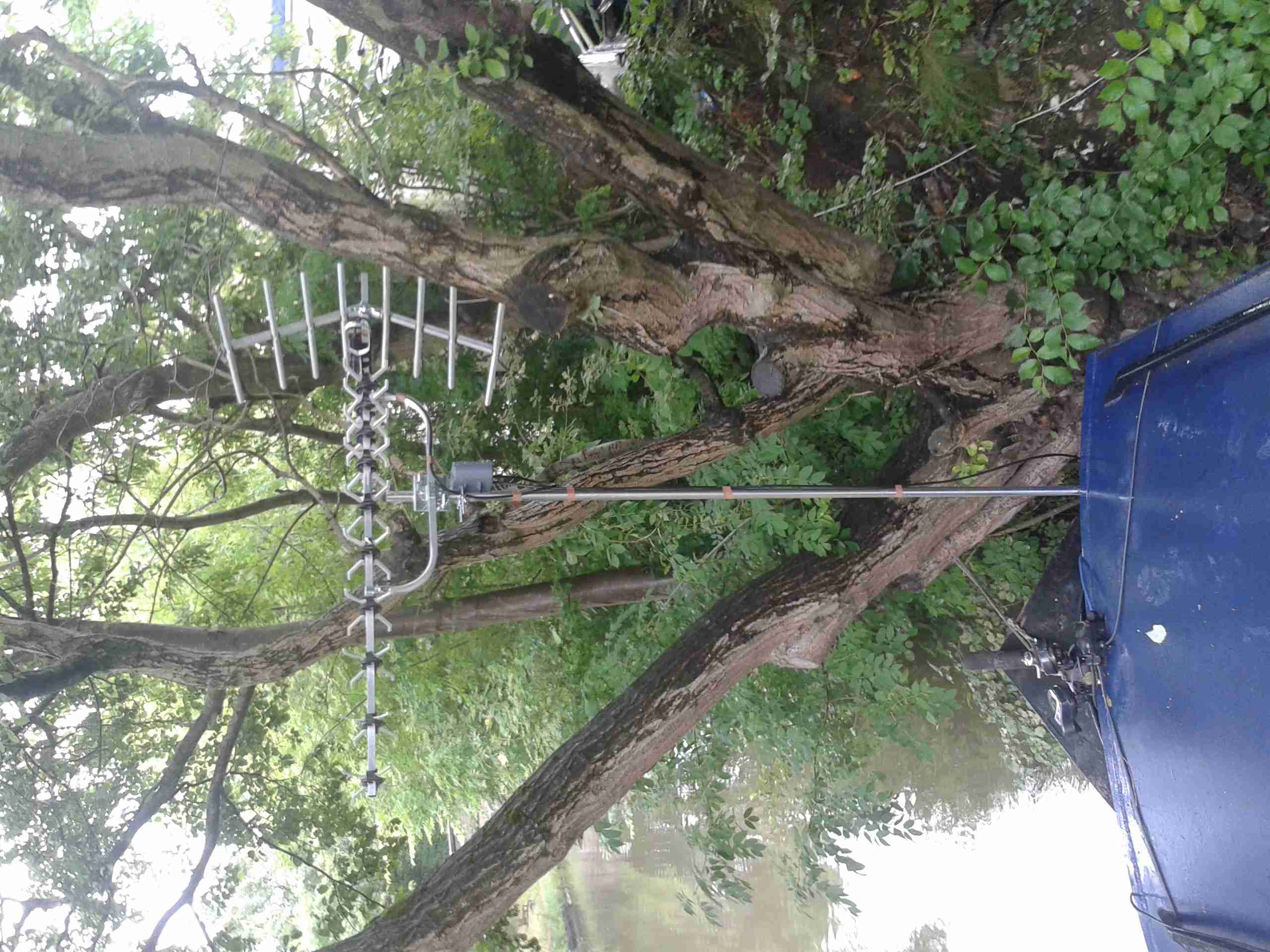
Here’s the new antenna on it’s removable mast. This apparently will give 13db of gain over the old antenna. The masthead amplifier box is mounted just below.
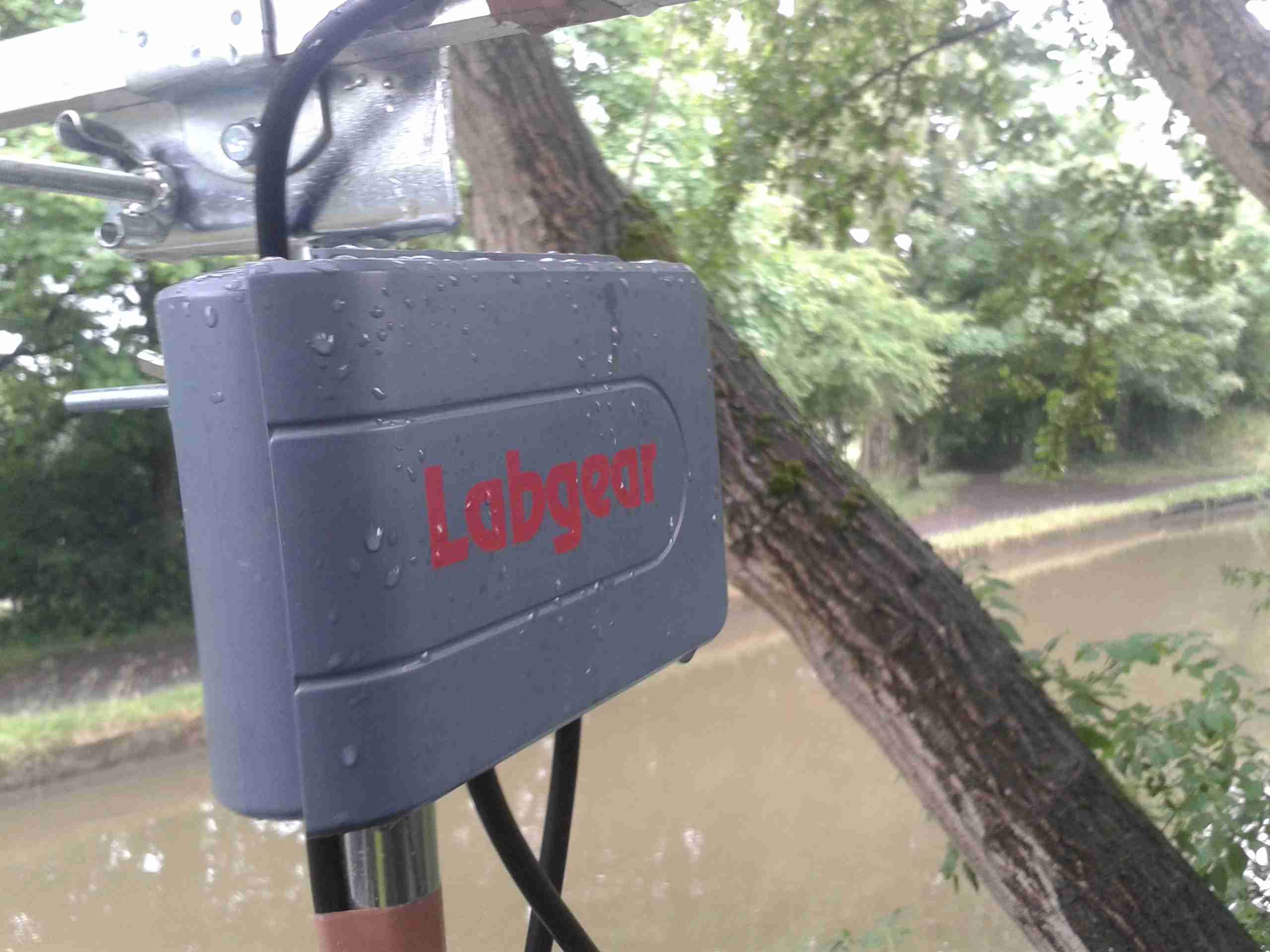
Here’s the amplifier just below the antenna. I do hope the seals on this hold against the weather! The amplifier inside isn’t protected at all.

Here’s the module itself. This is powered by +12v injected into the coax with the power supply I previously modified. F-type connectors are used. (I don’t like these connector types, their lack of a true centre pin is poor design in my opinion).
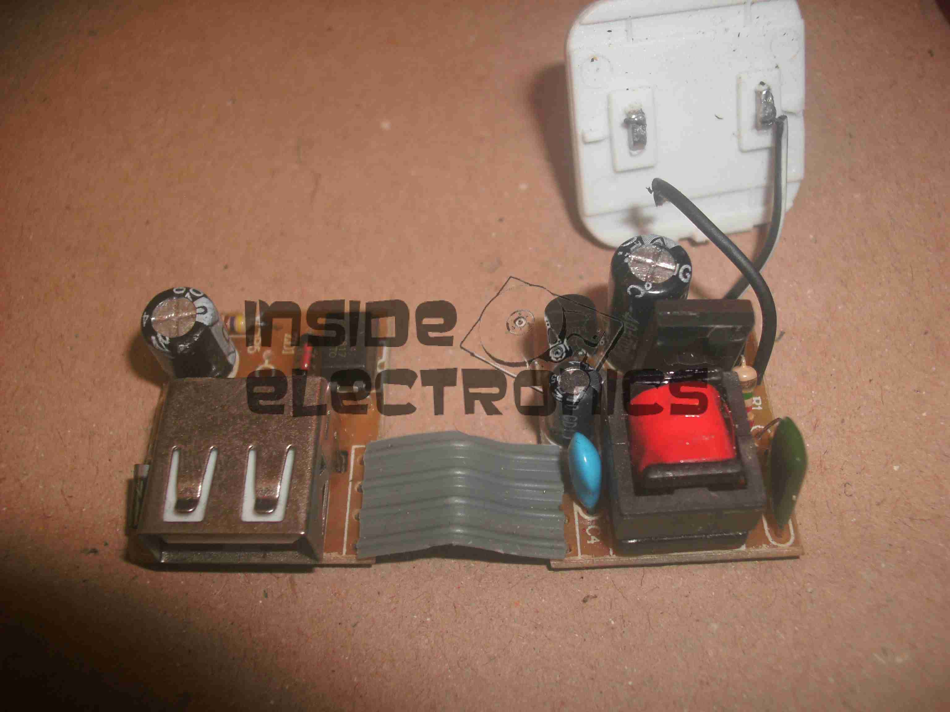
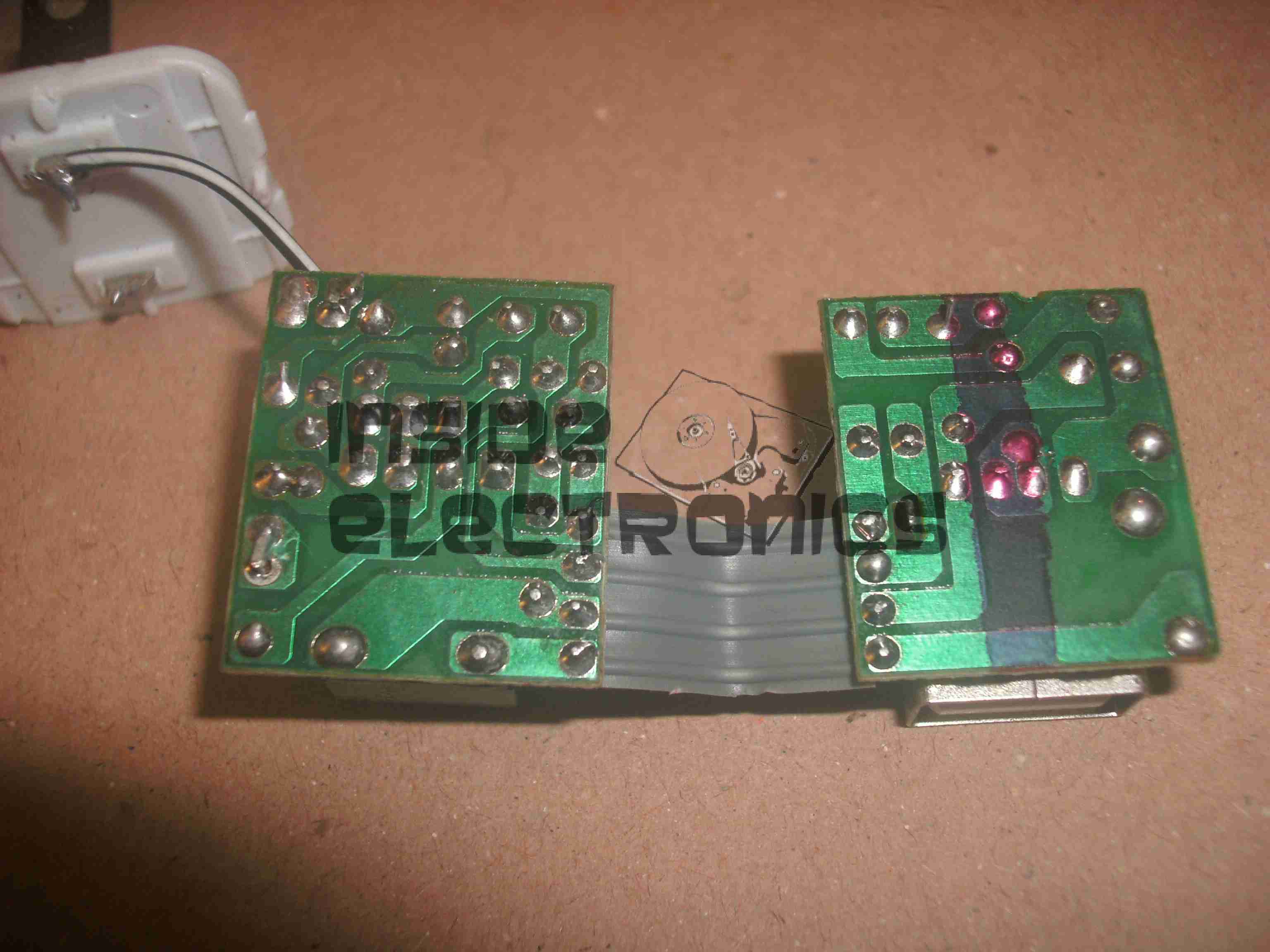
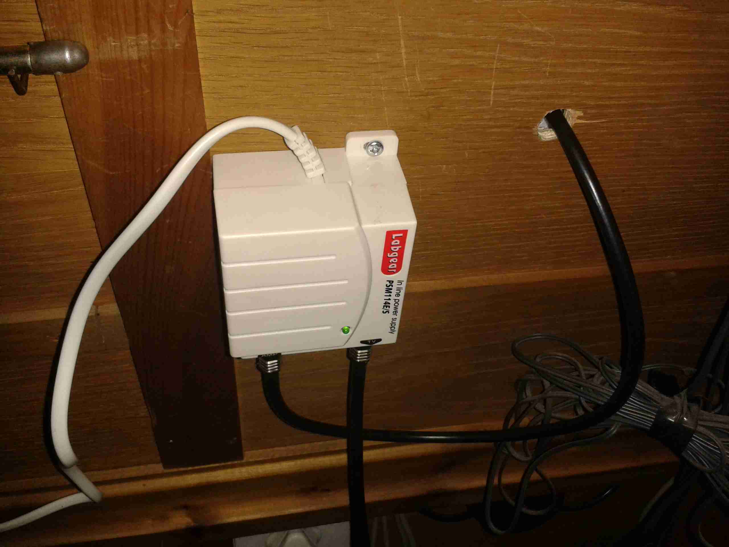
Here’s the power supply, mounted behind the TV where the cable comes through the hull.
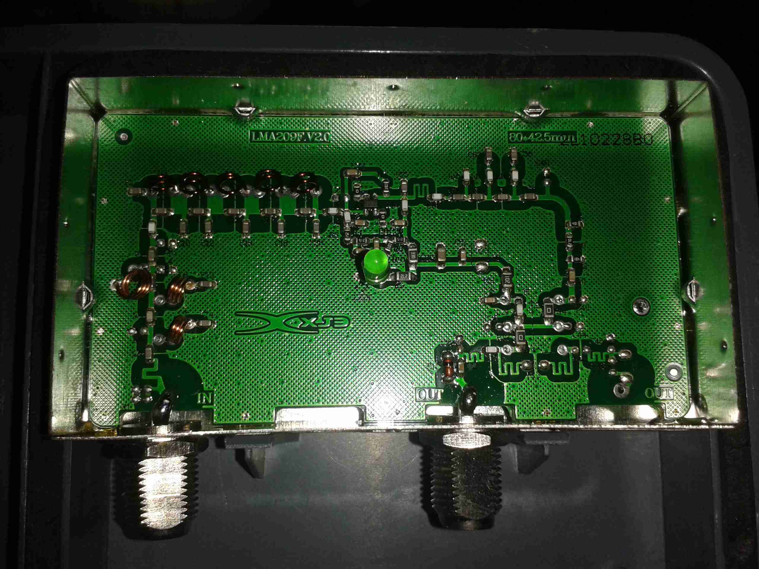
Here’s the inside of the amplifier module. It’s very simple, with some input filtering to block out 4G mobile signals, and a single amplifier transistor.