Posted on 8 Comments

Virgin Media Superhub 2 Teardown

I recently got the latest upgrade from Virgin Media, 200Mbit DL / 20Mbit UL, and to get this I was informed I’d have to buy their latest hardware, since my existing CPE wouldn’t be able to handle the extra 5Mbit/s upload speed. (My bullshit detector went off pretty hard at that point, as the SuperHub 2 hardware is definitely capable of working fine with 20Mbit/s upload rates). Instead of having to return the old router, I was asked to simply recycle it, so of course the recycling gets done in my pretty unique way!
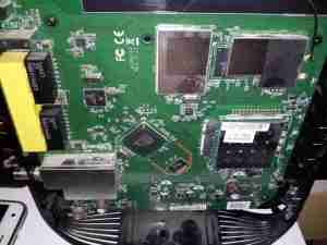
Mainboard
Mainboard

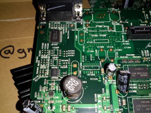
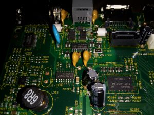
The casing of these units is held together by a single screw & a metric fuckton of plastic clips, disassembly is somewhat hindered by the radio antennas being positioned all over both sides of the casing. Once the side is off, the mainboard is visible. The DOCSIS frontend is lower left, centre is the Intel PUMA 5 Cable Modem SoC with it’s RAM just to the lower right. The right side of the board is taken up by both of the WiFi radio frontends, the 5GHz band being covered by a Mini PCIe card.
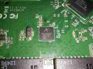
Atheros Gigabit Switch

The 4 gigabit Ethernet ports on the back are serviced by an Atheros AR8327 Managed Layer 3 switch IC, which seems to be a pretty powerful device:

The AR8327 is the latest in high performance small network switching. It is ultra low power, has extensive routing and data management functions and includes hardware NAT functionality (AR8327N). The AR8327/AR8327N is a highly integrated seven-port Gigabit Ethernet switch with a fully non-blocking switch fabric, a high-performance lookup unit supporting 2048 MAC addresses, and a four-traffic  class Quality of Service (QoS) engine. The AR8327 has the flexibility to support various networking applications. The AR8327/AR8327N is designed for cost-sensitive switch applications in wireless AP routers, home gateways, and xDSL/cable modem platforms.

Unfortunately most of the features of this router are locked out by VM’s extremely restrictive firmware. With any of their devices, sticking the VM supplied unit into modem mode & using a proper router after is definitely advised!
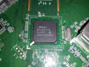
Intel Puma 5 CM CPU
Intel Puma 5 CM CPU

The cable modem side of things is taken care of by the Intel PUMA 5 DNCE2530GU SoC. This appears to communicate with the rest of the system via the Ethernet switch & PCI Express for the 5GHz radio.
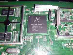
Atheros WiFi SoC
Atheros WiFi SoC

The 2.4GHz radio functionality is supplied by an Atheros AR9344 SoC, it’s RAM is to the left. This is probably handling all the router functions of this unit, but I can’t be certain.
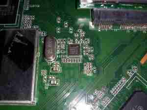
Atheros LAN PHY
Atheros LAN PHY

A separate Ethernet PHY is located between the SoC & the switch IC.
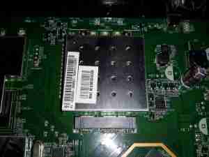
 

5GHz Radio Card
5GHz Radio Card

The 5GHz band is served by a totally separate radio module, in Mini PCIe format, although it’s a bit wider than standard. This module will probably be kept for reuse in another application.
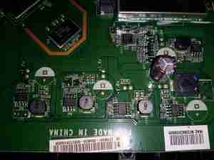
Power Supplies
Power Supplies

All down the edge of the board are the multiple DC-DC converters to generate the required voltage rails.
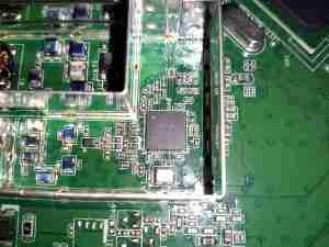
MaxLinear MXL261 Frontend

The DOCSIS frontend is handled by a MaxLinar MXL261 Tuner/Demodulator. More on this IC in my decapping post 🙂
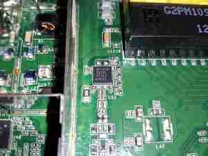
The Unknown One
The Unknown One

I’ve honestly no idea what on earth this Maxim component is doing. It’s clearly connected via an impedance matched pair, and that track above the IC looks like an antenna, but nothing I search for brings up a workable part number.
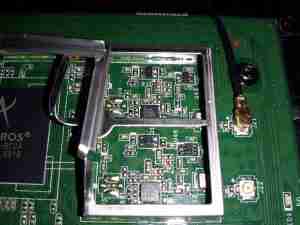
2.4GHz Frontend
2.4GHz Frontend

The RF switching & TX amplifiers are under a shield, these PA chips are SiGe parts.
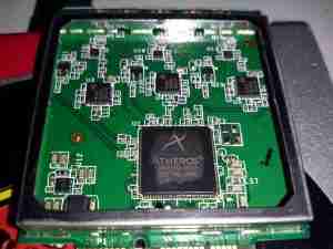
Atheros 5GHz Radio
Atheros 5GHz Radio

Pretty much the same for the 5GHz radio, but with 3 radio channels.
Posted on 1 Comment

Sky+ HD Set Top Box

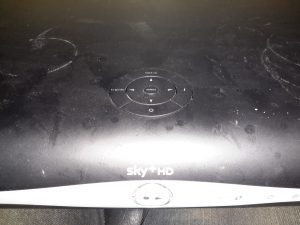
Sky Box
Sky Box

Time for another teardown! I managed to fish this Sky+ box out of a skip, but to protect the guilty, all serial numbers have been removed.
These are pretty smart devices, with DVR capability on board.

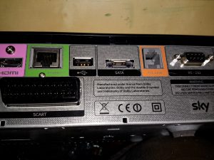
Ports 1
Ports 1

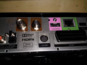
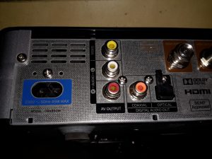
There’s a lot of ports on these units, from RS-232 serial, POTS modem, eSATA, HDMI, USB, Ethernet, SCART, Optical, digital outputs & even composite video.

Ports 2
Ports 2
Ports 3
Ports 3
Top Panel
Top Panel

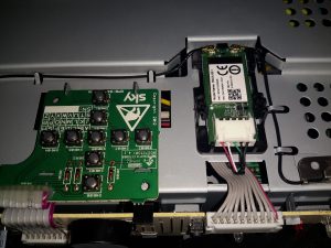
Removing the top plastic cover reveals the operation buttons & the built in WiFi adaptor, which is USB connected to the main logic board.

Front Panel
Front Panel

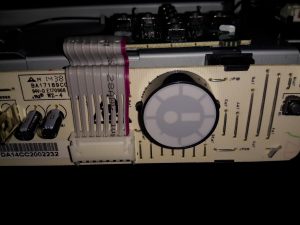
The PCB on the front of the chassis has all the indicators, and the IR Receiver for the remote.

Cover Removed
Cover Removed

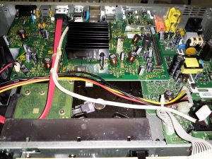
Removing the top shield of the chassis reveals the innards. The PSU is on the top right, 500GB SATA disk drive in the bottom centre. The main logic PCB is top centre.

Logic PCB
Logic PCB

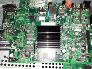
Here’s the main logic PCB. The massive heatsink in the middle is cooling the main SoC, below.

SoC
SoC

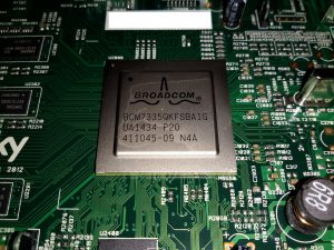
The main SoC in this unit is a Broadcom BCM7335 HD PVR Satellite System-On-Chip. It’s surrounded by it’s boot flash, a Spansion GL512P10FFCR1 512Mbit NOR device. It’s also got some DRAM around the left edge.

Smart Card Reader
Smart Card Reader

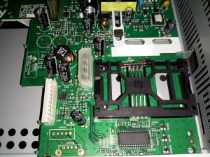
The smart card reader is on the PSU PCB, the controller here is an NXP TDA8024

PSU PCB
PSU PCB

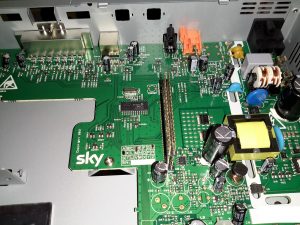
The PSU itself is a pretty standard SMPS, so I won’t go too far into that particular bit. The logic PCB attaches to the large pin header on the left of the PSU, some of the analogue video outputs are also on this board.
There’s also a Microchip PIC16F726 microcontroller on this PCB, next to the pin header. Judging by the PCB traces, this handles everything on the user control panel.

Power Supplies
Power Supplies

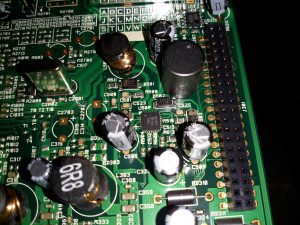
Some local supplies are provided on the logic board for the main SoC, the IC in the centre here is an Allegro A92 DC-DC converter. I didn’t manage to find a datasheet for this one.

LNB Front End
LNB Front End

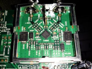
The RF front end for the satellite input is a Broadcom BCM3445 Low Noise Amplifier & Splitter, again not much info on this one.

RS232 Section
RS232 Section

The standard MAX232 is used for the serial interface. I imagine this is for diagnostics.

Modem
Modem

The POTS modem section is handled by a Si2457 System-Side device & Si3018 Line-Side device pair.

The Shack

The Shack

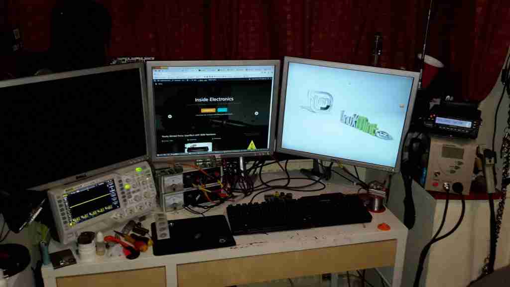
So, here is where all the action happens.

Main radio of course is housed on the left, it’s partially hidden under my currently over-populated breadboard.

All 3 monitors are linked to the same PC, using a pair of video cards. This is a very flexible system with so much screen real estate.

Main system power is provided by the pair of power supplies next to the radio – these are homebrew units using surplus switched mode PSU boards. Check my previous posts for more details.

Power Supplies
Power Supplies

The main power supply system. These two supplies are cross connected, giving a total DC amperage of 30A at 13.8v. There is also a link to a large 220Ah lead-acid battery bank (orange cable), to keep me on the air during power outages. This cable is getting upgraded to something more beefy shortly. The white cable is currently supplying power to my online radiation monitor.
The main high-current DC outputs are the Speakon connectors next to the meters. The top one is powering the radio directly, the bottom is linked through to my 12v distribution box for lower current loads, such as the oscilloscope, audio amplifiers, tools, etc.

Radiation Monitor
Radiation Monitor

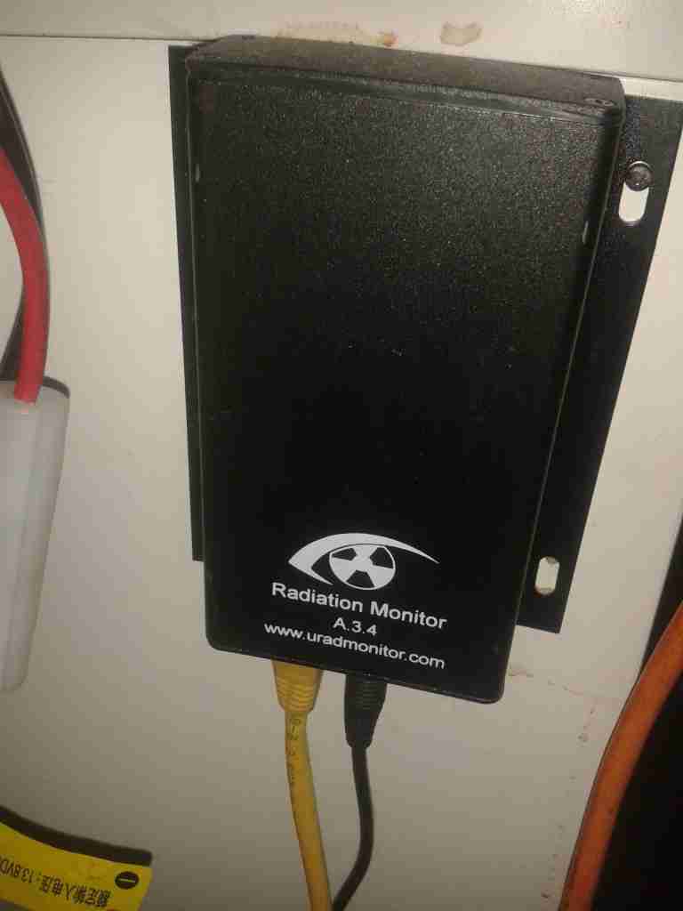
Attached to the side of the desk is the radiation monitor itself.

Core NAS
Core NAS

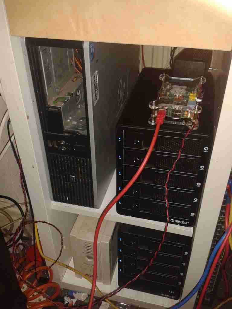
Under the radio is the core NAS of the network. It’s an array of 9 4TB disks, in RAID6, giving a total capacity after parity of 28TB. This provides storage & services to every other machine in the shack, the Raspberry Pi on top of the disk array is doing general network housekeeping & monitoring, also generating the graphs for the Radiation Monitor page. A Cisco 48-port switch is partially out of frame on the right, providing 100MB Ethernet to the devices that don’t require gigabit.