Posted on 5 Comments

Vodafone Mobile WiFi R207 Teardown

Vodafone Mobile WiFi R207

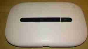
Here’s one of the old modems from my spares bin, a Vodafone Mobile WiFi R207. This is just a rebranded Huawei E5330. This unit includes a 3G modem, and a WiFi chipset, running firmware that makes this a mini-router, with NAT.
Specs
Specs

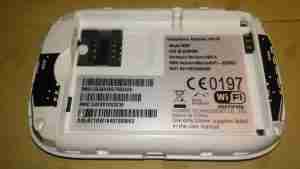
The back has the batter compartment & the SIM slot, with a large label showing all the important details.
Cover Removed
Cover Removed

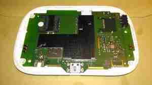
A couple of small Torx screws later & the shell splits in half. All the electronics are covered by shields here, but luckily they are the clip-on type, and aren’t soldered direct to the PCB.
Chipset
Chipset

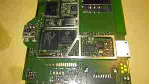
Once the shield has been removed, the main chipset is visible underneath. There’s a large Spansion MS01G200BHI00 1GBit flash, which is holding the firmware. Next to that is the Hi6758M baseband processor. This has all the hardware required to implement a 3G modem. Just to the right is a Hi6521 power management IC, which is dealing with all the power supplies needed by the CPU.
The RF section is above the baseband processor, some of which is hiding under the bits of the shield that aren’t removable.
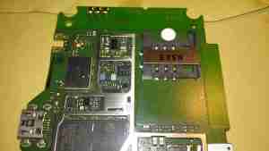
SIM Socket
SIM Socket

There’s a socket onboard for a standard Mini-SIM, just to the left of that is a Hi6561 4-phase buck converter. I would imagine this is providing the power supplies for the RF section & amplifier.
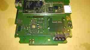
Unpopulated Parts
Unpopulated Parts

Not sure what this section is for, all the parts are unpopulated. Maybe a bluetooth option?
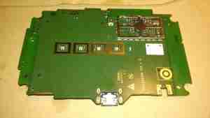
PCB Reverse
PCB Reverse

The other side of the PCB is pretty sparse, holding just the indicator LEDS, button & the WiFi Chipset.
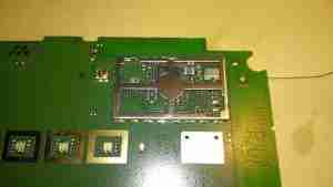
Realtek WiFi Chipset

The chipset here is a Realtek part, but it’s number is hidden by some of the shield. The antenna connection is routed to the edge of the board, where a spring terminal on the plastic case mounted antenna makes contact.
Posted on Leave a comment

Routemaster Control Unit

This is the control unit for a Routemaster system, that downloads traffic information for the area local to the vehicle.

Unit Overview
Unit Overview

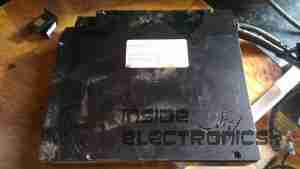
Here is an overview of the unit, in it’s aluminium box.


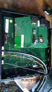
Here is the unit with the top cover removed, showing the pair of PCBs. The bottom PCB is the main control PCB, the top one holds an IC similar to a SIM card & part of the radio.

Cover Removed
Cover Removed


Main PCB Top
Main PCB Top

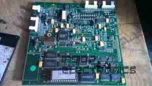
Here is the main PCB removed from the casing, contains the program ROM & microcontroller. for the system


Daughtercard view. This holds another programmed CPLD, the custom SIM-like IC & the RTC battery, along with some power conversion circuitry.

Daughterboard Top
Daughterboard Top


Radio Receiver
Radio Receiver

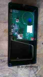
This is the radio receiver, looks to be AM, the large loop antenna can be seen at the bottom of the box.

Posted on Leave a comment

Motorola V360v

Front
Front

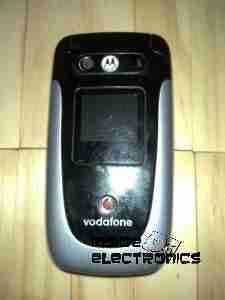
Here is a more modern phone, the Motorola V360v. Features include Dual screens, 640×480 VGA camera, full col

our TFT Main LCD, SD-Micro slot.
Here on the back the grey scale LCD can be seen, with the camera lens to the right of the Motorola logo

Keypad
Keypad

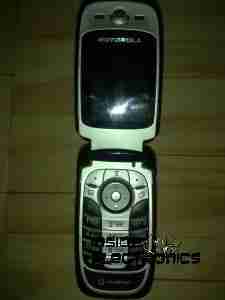
Here the phone is opened showing the keypad & the full colour TFT LCD display.

Battery Compartment
Battery Compartment

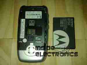
Here the battery is removed from the unit, showing the SIM connector. The antenna cover is still on at the bottom.

Antenna
Antenna

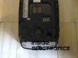
The antenna cover has been removed in this shot, the antenna is the white section at the bottom, With the loudspeaker & the external antenna connector hidden at the right.

PCB
PCB

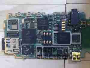
Here is the main PCB. Parts from left are the Bluetooth module at the top, supplied by Broadcom, the SD Card socket at the bottom. Main CPU next to that is the Freescale SC29343VKP. Above right of the CPU is the Freescale SC13890P23A Charger, Power & Audio IC. Below is the SIM card socket. Under the main CPU is the Intel Flash memory IC. ICs inside the shields are the RF sections for transmit & receive.

Cover Removed
Cover Removed

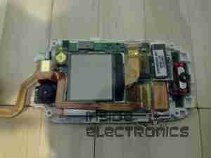
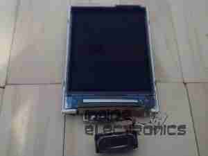
Rear of the display unit showing the monochrome LCD. The camera module on the bottom left. Ear speaker on the far right of the unit.

Main LCD
Main LCD

Main colour TFT LCD.

Camera
Camera

Camera module removed from the LCD unit.

Vibra-Motor
Vibra-Motor

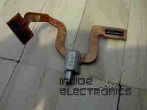
The vibration motor attached to one of the LCD looms.

Posted on Leave a comment

Ericsson GA628

Front
Front

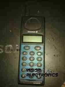
Here is a phone from the mid 90s, the Ericsson GA628. Here visible is the front of the unit with keypad, & single line monochrome LCD for number display.

Battery & Rear
Battery & Rear

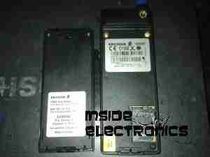
Here the battery is removed from the phone, showing the SIM card socket. At the top under the antenna stub is the socket for an external antenna.

Front Removed
Front Removed

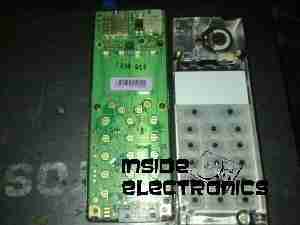
Here the front is removed from the phone, PCB on left, rear of keypad on right. Microphone is at bottom of keypad, with speaker at the top. Top right of the PCB is the ringer buzzer, left is shield for RF amplifier.

Main PCB
Main PCB

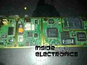
Here is the back of the main PCB, RF sections on left & centre. Processing & memory on right.

Battery
Battery

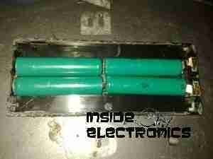
This phone had a Ni-Mh battery, before Li-Ion batteries were introduced.

LCD
LCD

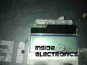
The LCD from the front of the phone is shown here. A simple dot matrix single line unit.