Posted on Leave a comment

Chicom “500W” ATX PSU

Cover Removed
Cover Removed

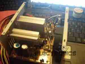
Here is a cheapo 500W rated ATX PSU that has totally borked itself, probably due to the unit NOT actually being capable of 500W. All 3 of the switching transistors were shorted, causing the ensuing carnage:
AC Input
AC Input

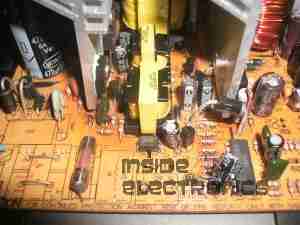
Here is the AC input to the PCB. Note the vapourised element inside the input fuse on the left. There is no PFC/filtering built into this supply, being as cheap as it is links have been installed in place of the RFI chokes.

Input Side
Input Side

Main filter capacitors & bridge rectifier diodes. PCB shows signs of excessive heating.
Filter Caps Removed
Filter Caps Removed

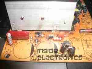
Filter capacitors have been removed from the PCB here, showing some cooked components. Resistor & diode next to the heatsink are the in the biasing network for the main switching transistors.
Heatsinks Removed
Heatsinks Removed

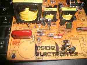
Heatsink has been removed, note the remaining pin from one of the switching transistors still attached to the PCB & not the transistor 🙂
Transformers
Transformers

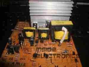
Output side of the PSU, with heatsink removed. Main transformer on  the right, transformers centre & left are the 5vSB  transformer & feedback transformer.
Output Side
Output Side

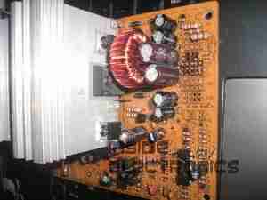
Output side of the unit, filter capacitors, choke & rectifier diodes are visible here attached to their heatsink.
Comparator
Comparator

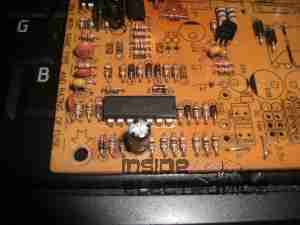
Comparator IC that deals with regulation of the outputs & overvoltage protection.
Posted on Leave a comment

Southwestern Bell Freedom Phone

Phone
Phone

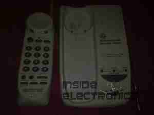
This is an old cordless landline phone, with dead handset batteries.

Handset Radio Board
Handset Radio Board

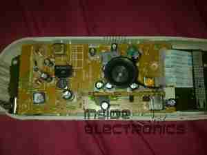
Here’s the handset with the back removed. Shown is the radio TX/RX board, underneath is the keyboard PCB with the speaker & mic. All the FM radio tuning coils are visible & a LT450GW electromechanical filter.

Handset Radio Board Bottom

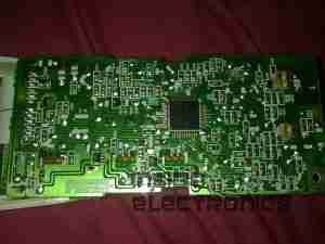
Radio PCB removed from the housing showing the main CPU controlling the unit, a Motorola MC13109FB.

Keypad Board
Keypad Board

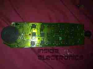
The keypad PCB, with also holds the microphone & speaker.

Handset Keypad Board Bottom

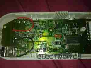
Bottom of the keypad board, which holds a LSC526534DW 8-Bit µC & a AT93C46R serial EEPROM for phone number storage.

Base Main Board
Base Main Board

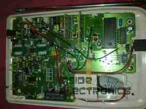
Here’s the base unit with it’s top cover removed. Black square object on far right of image is the microphone for intercom use, power supply section is top left, phone interface bottom left, FM radio is centre. Battery snap for power backup is bottom right.

Power Supply Section

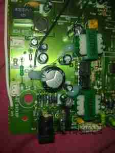
PSU section of the board on the left here, 9v AC input socket at the bottom, with bridge rectifier diodes & main filter capacitor above. Two green transformers on the right are for audio impedance matching. Another LT450GW filter is visible at the top, part of the base unit FM transceiver.

ICs
ICs

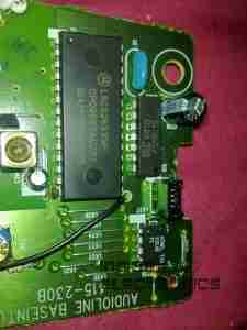
Another 8-bit µC, this time a LSC526535P, paired with another AT93C46 EEPROM. Blue blob is 3.58MHz crystal resonator for the MCU clock. The SEC IC is a KS58015 4-bit binary to DTMF dialer IC. This is controlled by the µC.

Base Main Board Bottom

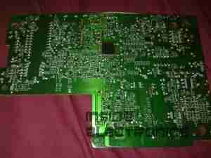
Underside of the base unit Main PCB, showing the matching MC13109FB IC for the radio functions.

Posted on Leave a comment

Bosch GSR 14.4v Pro Drill-Driver

Drill Case
Drill Case

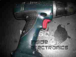
Here is a Bosch 14.4v Professional cordless drill/driver, recovered from a skip!
It was thrown away due to a gearbox fault, which was easy to rectify.

Internals
Internals

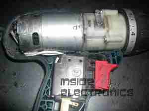
Here is the drill with the side cover removed, showing it’s internal parts. The speed controller is below the motor & gearbox here. The unit at the top consists of a 12v DC motor, coupled to a 4-stage  epicyclic gearbox unit, from which can be selected 2 different ratios, by way of the lever in the centre of the box. This disables one of the gear stages. There is a torque control clutch at the chuck end of the gearbox, this was faulty when found.

Motor
Motor

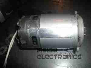
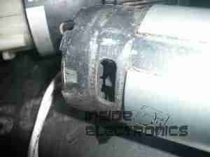
Here is the drive motor disconnected from the gearbox, having a bayonet fitting on the drive end.

Drive Gear
Drive Gear

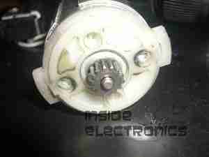
This is the primary drive gear of the motor, which connects with the gearbox.

Cooling Fan
Cooling Fan

The motor is cooled by this fan inside next to the commutator, drawing air over the windings.

Gearbox
Gearbox

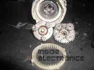
This is the gearbox partially disassembled, showing the 1st & second stages of the geartrain. The second stage provides the 2 different drive ratios by having the annulus slide over the entire gearset, disabling it entirely, in high gear. The annulus gears are a potential weak point in this gearbox, as they are made from plastic, with all other gears being made of steel.

Charger
Charger

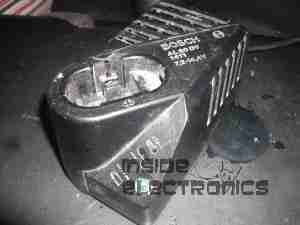
Here is the charging unit for the Ni-Cd battery packs supplied with the drill. The only indicator is the LED shown here on the front of the unit, which flashes while charging, & comes on solid when charging is complete. Charge termination is by way of temperature monitoring.

Transformer
Transformer

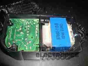
Here the bottom of the charger has been removed, showing the internal parts. An 18v transformer supplies power to the charger PCB on the left.

Charger PCB
Charger PCB

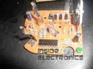
This is the charger PCB, with a ST Microelectronics controller IC marked 6HKB07501758. I cannot find any information about this chip.

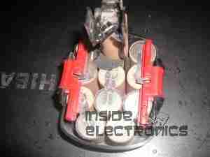
Battery Pack Internals

Here is a battery pack with the top removed, showing the cells.

Temperature Sensor
Temperature Sensor

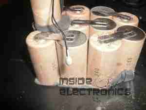
This is the temperature sensor embedded inside the battery pack that is used by the charger to determine when charging is complete.