Posted on 2 Comments

Ferguson A10RWH Portable Colour TV Teardown

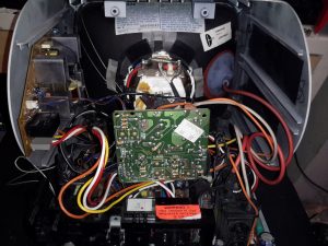
Back Removed
Back Removed

Here’s the other TV that was picked up from the local water point having been put of to be recycled. This one is much newer than the Thorn TV, a 10″ colour version from Ferguson.
RCA 27GDC85X CRT
RCA 27GDC85X CRT

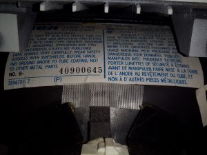
The colour CRT used is an RCA branded one, 27GDC85X.
Power Inputs
Power Inputs

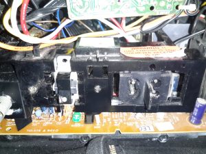
Like the other TV, this one is dual voltage input, mains 240v & 12v battery. This TV is a factory conversion of a standard 240v AC chassis though.
HV PSU
HV PSU

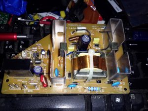
The 12v power first goes into this board, which looked suspiciously like an inverter. Measuring on the output pins confirmed I was right, this addon board generates a 330v DC supply under a load, but it’s not regulated at all, under no load the output voltage shoots up to nearly 600v!
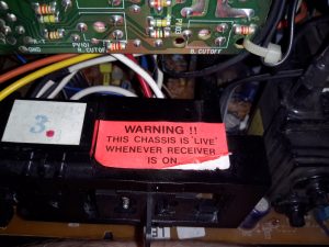
Live Chassis
Live Chassis

I’ve not seen one of these labels on a TV for many years, when back in the very old TV sets the steel chassis would be used to supply power to parts of the circuitry, to save on copper. Although it doesn’t have a metal chassis to actually become live, so I’m not sure why it’s here.
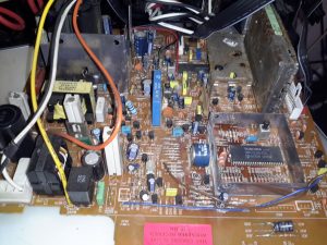
Main PCB
Main PCB

The main PCB is much more integrated in this newer TV, from the mid 90’s, everything is pretty much taken care of by silicon by this point.
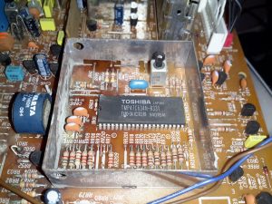
Main Microcontroller

This Toshiba µC takes care of channel switching & displaying information on the CRT. The tuner in this TV is electronically controlled.
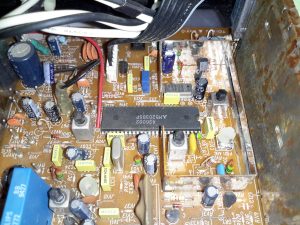
PAL Signal Processor

The video signal is handled by this Mitsubishi IC, which is a PAL Signal Processor, this does Video IF, Audio IF, Chroma, & generates the deflection oscillators & waveforms to drive the yoke.
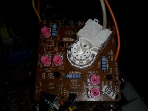
CRT Adjustments
CRT Adjustments

There are some adjustments on the CRT neck board for RGB drive levels & cutoff levels. This board also had the final video amplifiers onboard, which drive the CRT cathodes.
Posted on 2 Comments

Sony Watchman FD-280 Composite Video Hack

Hacked
Hacked

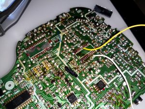
As with the previous Sony Watchman hack, injecting a composite video signal into this one is just as easy. I desoldered both the VIF/SIF IC & the digital tuner control (the tuner controller was still injecting it’s indicator into the video circuitry with the IF IC disconnected).

Composite video is on pin 18 of the Video IF IC, with the audio on Pin 13.

Posted on 1 Comment

Sony Watchman FD-20 Composite Video Hack

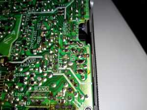
VIF IC Pads
VIF IC Pads

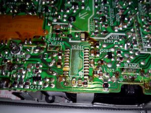
Hacking the Sony FD-20 to accept a composite input is easy – the tuner receives the RF transmission, produces an IF, this is then fed into IC201, a Mitsubishi M51364P Video IF Processor. The VIF IC then separates out the composite video signal, which is output on Pin 13 (in photo above, left side, 3rd pin from the top). The audio is separated out & sent via Pin 11 to the Audio IF processor.

In the above photo, the VIF IC has been removed from the board with hot air, as it was interfering with the signal if left in place. The RF tuner was also desoldered & removed. Unfortunately I managed to mangle a pad, which is the ground pin for the VIF IC. This isn’t much of an issue though, as an identical signal ground is available, just to the left of the IC.

Audio Input
Audio Input

The audio can be tapped into in a similar way, the circled pad in the centre of the photo marked SIF is the place, this is the output of the Audio IF processor to the audio amplifier. The Audio IF processor didn’t interfere with the injected signal, so it was left in place.

Posted on Leave a comment

Quickie Project: Ruggedising The RTL-SDR Dongle

As supplied, the RTL type tuner dongles are a little fragile, especially when they’ve got a rather heavy coax feeder attached for Ham Radio use.

The MCX antenna connectors on the tuner can’t stand up to much abuse, and even the USB plug rips itself from it’s mounts after a while with a heavy weight on the end. Since this dongle sits in my radio go bag, it definitely needed some protection & support.

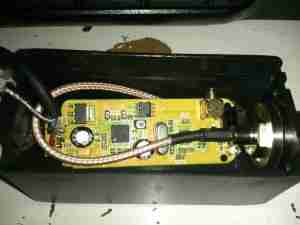
PCB
PCB

The PCB itself is removed from it’s flimsy plastic casing, the USB plug is desoldered from the board.
To the exposed pads, a USB cable is soldered, giving much more flexibility in where the tuner is placed.
Instead of using the MCX antenna connector on the PCB, the coax is stripped & soldered direct to the PCB itself, as this connector has become unreliable.

N-Connector
N-Connector

To get the RF into the device, the case is fitted with an N connector, as is everything else in my shack.

Boxed
Boxed

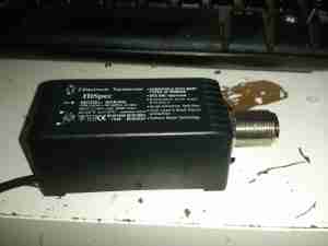
The box used is a surplus one which previously housed an electronic lighting transformer. This would be very easy to waterproof as well, for more protection against outdoor use.

Posted on 1 Comment

Hauppauge WinTV USB

Front
Front

Here is one of the first USB tuners that was available from Hauppauge Computer Works. Totally analog tuner of course, this model required 2 cables – a USB interface & a sound cable for the audio output of the tuner.

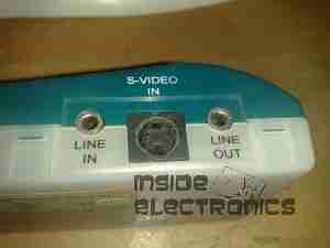
I/O
I/O

A/V connections.

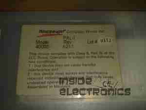
Label
Label

For those who are interested. Here is the label with the model details.

Antenna Connection
Antenna Connection

Connection to an external antenna.

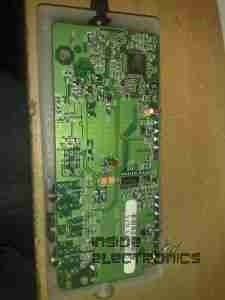
PCB Bottom
PCB Bottom

Bottom of the PCB.

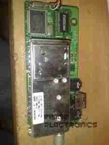
PCB Top
PCB Top

Top of the PCB showing the USB interface IC (top left), cache memory (top right) & the main tuner assembly.