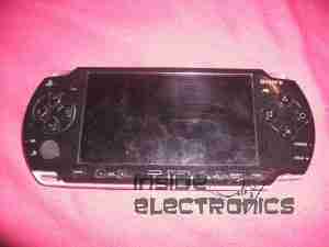
Here is a PSP Slim that recently died.

For those that are interested, here is the ID label, this is a PSP-2003.

Here the front of the unit has been removed, showing the first internal components.
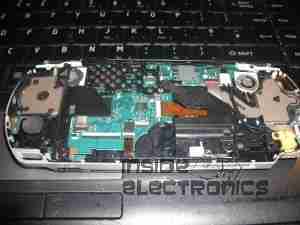
Here is the unit with the LCD removed, here the mainboard is partially visible.
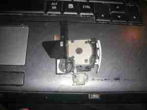
Left pad unit removed from the PSP, with the left speaker & the memory stick slot cover.

Rear of the left pad assembly, showing the speaker.
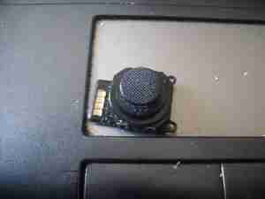
Joypad removed from the casing. Resistive unit.

Headphone/data board removed from the casing. This also has TV-Out on the PSP-200x series.
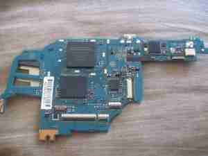
Mainboard removed. Main CPU is at the top. Sockets around the bottom connect to the UMD drive & UMD Drive.
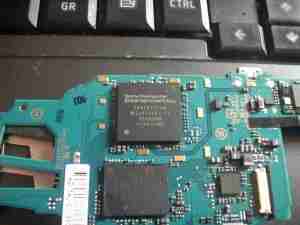
Closeup of the main chipset. CPU is the top IC.

Rear of the mainboard, Memory Stick socket on the right.

Closeup of the WiFi chipset & the charging power socket on the right.
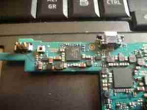
Closeup of the bettery connector & the charge controller IC.
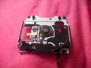
UMD Drive removed from the rear of the casing. This is a miniature DVD style drive, using a 635nm visible red laser.
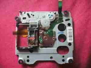
Rear of the UMD drive, showing the laser sled & drive motors. Both the spindle motor & the sled motor are 3-phase brushless type. The laser diode/photodiode array is at the top of the laser sled.
