Posted on 5 Comments

Vodafone Mobile WiFi R207 Teardown

Vodafone Mobile WiFi R207

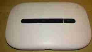
Here’s one of the old modems from my spares bin, a Vodafone Mobile WiFi R207. This is just a rebranded Huawei E5330. This unit includes a 3G modem, and a WiFi chipset, running firmware that makes this a mini-router, with NAT.
Specs
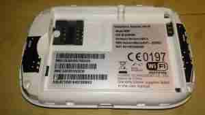
Specs

The back has the batter compartment & the SIM slot, with a large label showing all the important details.
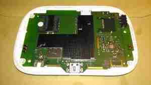
Cover Removed
Cover Removed

A couple of small Torx screws later & the shell splits in half. All the electronics are covered by shields here, but luckily they are the clip-on type, and aren’t soldered direct to the PCB.
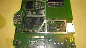
Chipset
Chipset

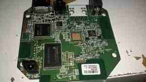
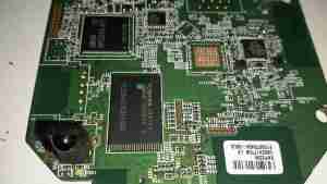
Once the shield has been removed, the main chipset is visible underneath. There’s a large Spansion MS01G200BHI00 1GBit flash, which is holding the firmware. Next to that is the Hi6758M baseband processor. This has all the hardware required to implement a 3G modem. Just to the right is a Hi6521 power management IC, which is dealing with all the power supplies needed by the CPU.
The RF section is above the baseband processor, some of which is hiding under the bits of the shield that aren’t removable.
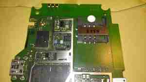
SIM Socket
SIM Socket

There’s a socket onboard for a standard Mini-SIM, just to the left of that is a Hi6561 4-phase buck converter. I would imagine this is providing the power supplies for the RF section & amplifier.
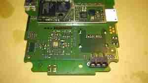
Unpopulated Parts
Unpopulated Parts

Not sure what this section is for, all the parts are unpopulated. Maybe a bluetooth option?
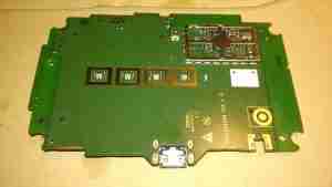
PCB Reverse
PCB Reverse

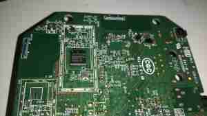
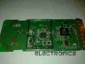
The other side of the PCB is pretty sparse, holding just the indicator LEDS, button & the WiFi Chipset.
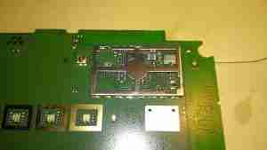
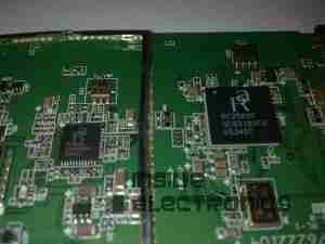
Realtek WiFi Chipset

The chipset here is a Realtek part, but it’s number is hidden by some of the shield. The antenna connection is routed to the edge of the board, where a spring terminal on the plastic case mounted antenna makes contact.

Posted on 4 Comments

Virgin Media Hub 3 Crap & Router Upgrades

I posted a while back a teardown of the VM Superhub 2 router, as VM has “upgraded” to a rebranded Arris TG2492S/CE CM. Alas Virgin Media in their wisdom have decided that simple router features like being able to change the LAN subnet & DHCP server range are far too complex to trust to the Great Unwashed, so they’ve removed them entirely from the firmware, and locked the local LAN onto the 192.168.0.0/24 range.
As my network is already numbered in the 10.0.0.0/16 range, with several statically addressed devices present and other systems relying on these static assignments, using this router would have meant renumbering everything.

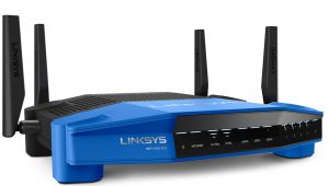
Luckily Virgin had the decency to leave the “modem mode” option in the firmware, effectively disabling the WiFi & routing functions & allowing the connection of a third-party router. Some searching for a suitable replacement for the core of my network turned up the Linksys WRT1900ACS. While I waited for this to arrive, some temporary workarounds were needed to make everything function well enough with VM’s crap router.

WRT1900ACS
WRT1900ACS

These routers have been designed as a modern replacement for the venerable WRT54G series of routers from some time ago, with full support for OpenWRT/DD-WRT firmware, and with a beefy 1.6GHz dual core CPU & 512MB of RAM I doubt I’ll be able to knock this one over with too much network traffic! This was pretty much the most powerful router I could afford, and should mean I don’t need to upgrade for a long time. (No teardown of this yet, as it’s taking care of the network at present. Maybe some point in the future I’ll take the plunge).

The stock firmware isn’t totally awful, and has some nice features, but I decided it needed to be replaced with DD-WRT for more security & future flexibility. I’ll leave the firmware flashing stuff for another post 😉

Posted on 2 Comments

Roku LT Teardown


Roku LT
Roku LT

Here’s another retired piece of tech that we used to route media from the NAS to the main TV. It was retired since it’s inability to support XBMC/Kodi & having some crashing issues.

Main PCB
Main PCB

After attacking the case with the screwdriver (Torx in this case), the main board comes out. The CPU in this looks *very* familiar, being a PoP device. There are unpopulated places for an ethernet interface & USB port here.

Flash & CPU
Flash & CPU

After a little digging is turns out the CPU in this device is a BCM2835, with 256MB of RAM stacked on top. It’s a Raspberry Pi! Even the unpopulated part for Ethernet is the same SMSC LAN9512!
There’s 32MB of Flash for the software below the CPU.
On the far right of the board is a Broadcom BCM59002IML Mobile Power Management IC.

WiFi Chipset
WiFi Chipset

On the bottom of the PCB is the WiFi chipset, a Broadcom BCM4336, this most likely communicates with the CPU via SDIO. There’s also a section below for a Bluetooth chipset.


Posted on Leave a comment

LB-Link USB Wireless-N Adaptor Teardown

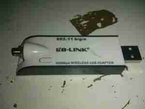
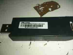
I needed a decent WiFi adaptor for my latest Pi LCD project, so after trawling eBay for cheapy USB adaptors, I found this one.

USB WiFi Dongle
USB WiFi Dongle

Unlike most USB WiFi radios these days, it actually has a proper RP-SMA antenna connector, not the low-gain built in jobbies that never seem to work too well.
There are a few versions of this adaptor, all of which seem to use the same casing, there’s a button push cut into the plastic for a WPS button that doesn’t exist on this model. This is fine, as I don’t enable WPS on any of my network equipment anyway. (It’s insecure, and can be cracked in minutes).

MAC Address
MAC Address

Here’s the rest of the essential details, the model is BL-LW08-AR, rated at 300Mbit/s.

PCB Reverse
PCB Reverse

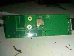
Here’s the PCB removed from the casing, there are a pair of PCB antennas on here, but they’re not connected to the RF circuitry in this model, the links are missing.

Chipset
Chipset

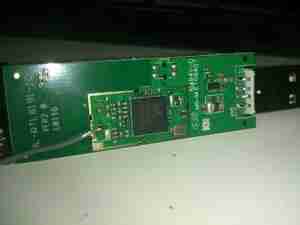
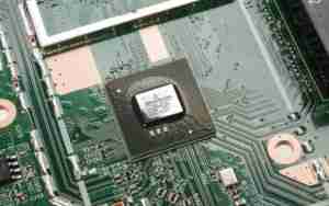
The chipset used is a Realtek RTL8191SU, there isn’t much more in this device, as it’s all built into the silicon.


Posted on 2 Comments

Cisco EA6700 / Linksys AC1750 Router

Cisco EA6700
Cisco EA6700

Since the boat was still running it’s internal network on 10/100M speeds, an upgrade was decided on, the internal WiFi signal strength was also pretty poor further than a few feet from the NOC.

The new router is a Cisco/Linksys AC1750 model, with gigabit networking, and full 802.11ac 2.4/5GHz Wireless. This router also has a built in media server, print server, USB3 & USB2.

PCB Overview
PCB Overview

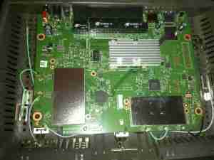
Teardown time! Here’s the router with the cover removed. Most of the fun stuff is hidden under the shields, but these aren’t fully soldered down & the covers are removable. The 6 antennas can be seen spaced around the edge of the housing, the main CPU is under the large heatsink upper centre. The radio power amplifier stages are underneath the shields, while the main RF transceivers are just outside the shields.

2.4GHz Transceiver
2.4GHz Transceiver

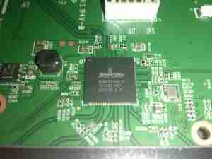
Wireless N is provided by a Broadcom BCM4331, this provides full dual-band 3×3 802.11n support. Being 3×3 it is actually 3 separate transceivers in a single package, to get much higher throughput rates of 600Mbit/s.

5GHz Transceiver
5GHz Transceiver

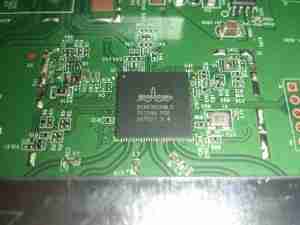
Wireless AC is provided by it’s sister IC, the BCM4360, with throughput speeds of 1.3Gbit/s. Both of these transceiver ICs connect back to the main CPU via PCI Express.

5GHz Power Amplifiers

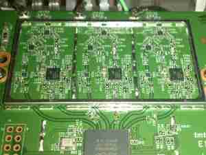
To get increased range, there are a trio of Skyworks SE5003L +23dBm 5GHz power amplifier ICs under the shield, along with the TX/RX switching & antenna matching networks. Heatsinking for these is provided by a sink screwed to the bottom side of the PCB. The outputs to the antennas can be seen at the top of the image.

2.4GHz Power Amplifiers

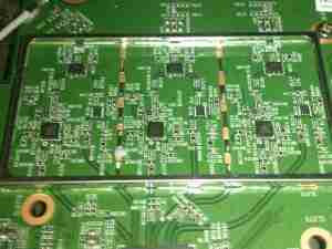
The 2.4GHz section is fitted with a trio of Skyworks SE2605L +23dBm 2.4GHz power amplifiers, with a similar heatsink arrangement under the board. Unlike the 5GHz section, the 2.4GHz antenna feeds are soldered to the PCB here instead of using connectors.

Main CPU
Main CPU

The main CPU is a BCM4708 Communications Processor from Broadcom, as for the other Broadcom chips in this router, very little information is available unless under NDA, but I do know it’s a dual core ARM Cortex A9 running at 1GHz, with built in 5-port gigabit ethernet switch.

CPU RAM
CPU RAM

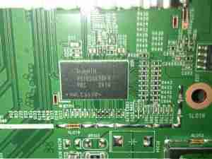
Working RAM for the processor is a Hynix H5TQ2G63DFA 256MB part.

More to come on the installation of the new networking, with it’s associated 4G mobile gateway connection system.

73s for now!

Posted on Leave a comment

Wearable Raspberry Pi Part 1.5

USB Ports
USB Ports

For convenience, a pair of USB ports have been fitted to the wearable Pi, which open on the bottom of the unit. These will be hardwired into a 4-port USB hub which will also support the wireless adaptor for the mini-keyboard that is to be used with the device.

USBs
USBs

The two USB ports on the bottom of the casing.

External Connections

The external connectors are also complete. The audio jack & second WiFi antenna port are fitted.

The audio is normally routed to the LCD display speaker, until a jack is plugged into the 3.5mm socket.


Posted on Leave a comment

Belkin PCMCIA Wi-Fi Card

Top label
Top label

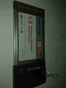
Here is an old Belkin Wireless G network card. This is a PCMCIA version.

Bottom Label
Bottom Label

Here is the bottom of the device, with all the details.

Antenna
Antenna

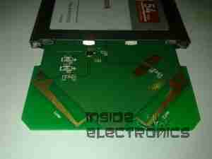
Plastic antenna cover removed, showing the pair of 2.4GHz etched antennae. There is a pair of LEDs on the upper left of the PCB showing activity & link status.

PCB
PCB

Overall view of the PCB, antennae on the left, RF chipset in centre, WiFi controller IC on right, and PCMCIA socket on far right. Can below wireless controller is a quartz crystal for the clock.

Chipset
Chipset

Closeup of the chipset, a Ralink RT2560F wireless controller on the right & a RT2525L transceiver on the left.