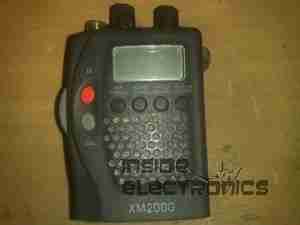
Here is an old XM2000 marine VHF tranciever.
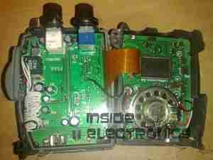
Here is the casing split, with the main CPU board & display on the right, & the RF tranciever board on the left.
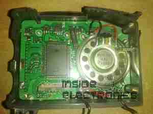
View of the main CPU board, with the mic & loudspeaker on the right hand side.
The channel display is on the reverse side of the PCB.
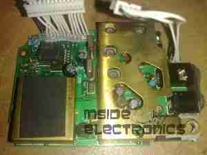
View of the RF board, with it’s brass shielding attached. This radio will transmit at 5W max.
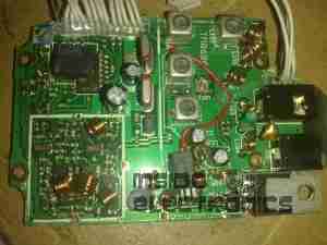
Shielding removed, power regulation bottom right corner of the board, tranciever on the left.
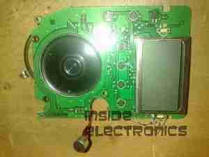
CPU board removed from the casing, showing the LCD & the user buttons to the left.
